
dji ROBOMASTER TT Mission Pad and Flight Map User Guide
V1.0 2021.04
Introduction
Mission pads and flight maps are accessories used for programming the RoboMaster TT (Tello Talent): The vision sensor of the drone detects the IDs of different mission pads and returns the relevant three-dimensional coordinates in order to execute the corresponding programming commands.
TT comes standard with four mission pads with different patterns on the front and back, for a total of eight IDs. The patterns on mission pad consist of three parts: a small rocket, the mission pad ID, and planets.
Small rocket: This represents the positive direction of the x-axis in the mission pad coordinate system.
Mission pad ID: The pads are numbered 1-8, allowing users to distinguish between different mission pads.
Planets: TT recognizes the ID of the mission pad by detecting the arrangement of the planets and obtains the coordinate values in the coordinate system of the mission pad.
TT supports 3×3 m and 5×5 m flight maps, which can be regarded as large mission pads used in the same way with the flight maps, TT can perform single-drone fixed-point flight and multi-drone formation flight. The pattern of the flight map is composed of DJI Logo, decorative pattern, and planets.

DJI logo: This represents the positive direction of the x-axis in the mission pad coordinate system.
Decorative pattern: For decoration.
Planets: TT recognizes the ID of the fight map by detecting the arrangement of the planets and obtains the coordinate values in the coordinate system of the flight map.
Download and print the source files of the flight maps or purchase them from a dealer. Note that the maps must be printed on matte, textured, rough, and non-reflective material so they can be recognized by the vision sensor of the drone.
Download the source files of flight maps at: https://www.dji.com/robomaster-tt/downloads
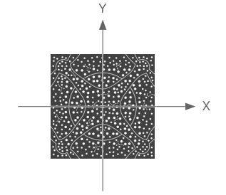
About the Mission Pad Coordinate System
The mission pad pattern contains a three-dimensional coordinate system, where the origin is at the center and the mission pad is a plane described by an x-axis and y-axis. Each mission pad provides an independent relative coordinate system. The coordinate systems of different mission pads do not affect each other, so they can be combined and placed as required.

Operations
The mission pads only work with TT or Tello EDU drones that support SDK 2.0 or later versions.
- Mission pad placementPlace the mission pad on a level surface and adjust the orientation of the rocket as needed.
- Enable TT mission pad detection
- Place TT in the center of the mission pad and enter the SDK mode (refer to the RoboMaster TT SDK instructions for details).
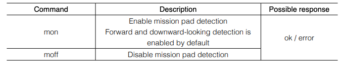
- After entering SDK mode, enable the mission pad detection function of TT with the “mon” command.
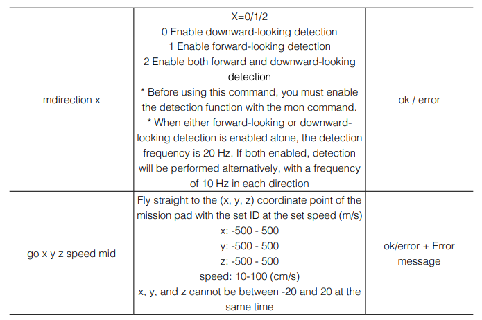
- Enable forward or downward-looking mission pad detection with the “mdirection x” command as needed.
- Have TT recognize the mission padCommand the TT to take off and hover. Instruct Tello to recognize the mission pad using the mid parameter in the SDK and perform corresponding flight actions based on the coordinates and ID information.
Command Descriptions
The following commands are used for mission pads.
mid: m1/m2…m7/m8/m-1/m-2m1/m2…m7/m8: Correspond to the ID of the mission pad.m-1: TT picks a detected mission pad at random.m-2: TT detects the mission pad closest to its center.
Example: go 100 100 100 60 m1
Description: TT detects the mission pad with ID 1 with the enabled mission pad detection function. If recognition succeeds, it will fly straight to the coordinate point (100, 100, 100) in the mission pad coordinate system at a speed of 60 cm/s. If recognition fails, it will hover in the air, return an error, and wait for the next command.
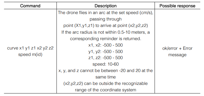
Example: curve 0 0 100 100 100 100 40 m2
Description: TT detects the mission pad with ID 2 with the enabled mission pad detection function. If recognition succeeds, the drone will fly to the coordinate point (0, 0, 100) and then to the coordinate point (100, 100, 100) in the mission pad coordinate system along an arc at a speed of 40 cm/s. If recognition fails, it will hover, return “Error. Not valid marker”, and wait for the next command.
* The arc is the short arc of the only circle formed by the current position of the drone, (0, 0, 100) and (100, 100, 100).If the three points are on a straight line or the radius of the resulting circle is not within the range of 0.5 m – 10 m, an error is returned.
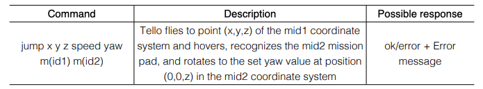
Example: jump 100 100 100 40 90 m1 m2
Description: TT detects the mission pad with ID 1 with the enabled mission pad detection function. If recognition succeeds, TT will fly to (100, 100, 100) in the mission pad coordinate system at the speed of 40 m/s, hover, and attempt to recognize the mission pad with an ID of 2. If this mission pad is recognized, the drone will rotate to a position 90° relative to the x-axis in the coordinate system of the ID 2 pad.
If recognition fails in either recognition process, the drone will hover and return “Error. Not valid marker”.
TELLO Status
When the host computer sends “command” to Tello UDP port 8889 to enter the SDK mode, Tello will send Tello status information to UDP port 8890 of the host computer. The data is a string, and the content is as follows:“mid:%d;x:%d;y:%d;z:%d;mpry:%d,%d,%d;pitch:%d;roll:%d;yaw:%d;vgx:%d;vgy%d;vgz:% d;temp l:%d;temph:%d;tof:%d;h:%d;bat:%d;baro:%f;\r\n”
Description
- Mid: For the detected ID of the mission pad, -2 will be returned if the mission pad detection function is not enabled, and -1 if the function is enabled but no pad is detected.
- x: The x-axis coordinate of the drone relative to the detected mission pad (in centimeters). -200 will be returned if the mission pad detection function is not enabled, and -100 if no pad is detected.
- y: The y-axis coordinate of the drone relative to the detected mission pad (in centimeters). -200 will be returned if the mission pad detection function is not enabled, and -100 if no pad is detected.
- z: The z-axis coordinate of the drone relative to the detected mission pad (in centimeters). -200 will be returned if the mission pad detection function is not enabled, and -100 if no pad is detected.
- mpry: The pitch, yaw, and roll angles and degrees of the drone in the mission pad. If the mission pad is not detected, 0 will be returned.
- pitch: Pitch angle (in degrees)
- roll: Roll angle (in degrees)
- yaw: Yaw angle (in degrees)
- vgx: X-axis speed (dm/s)
- vgy: Y-axis speed (dm/s)
- vgz: Z-axis speed (dm/s)
- templ: The lowest temperature of the main board (°C)
- temph: The highest temperature of the main board (°C)
- tof: ToF distance (cm)
- h: Height relative to take-off point (cm)
- bat: Percentage of current remaining battery capacity
- baro: Height detected by barometer (m)
- time: Motor running time (s)
- agx: X-axis acceleration (cm/s2)
- agy: Y-axis acceleration (cm/s2)
- agz: Z-axis acceleration (cm/s2)
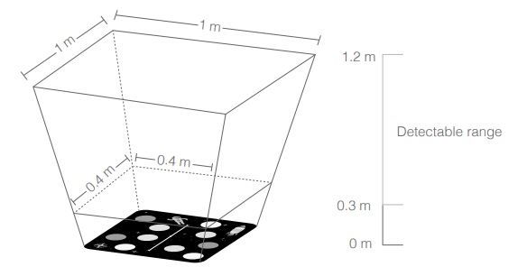
Effective Mission Pad Recognition Range
Recognizable height range: 0.3 – 1.2 mRecognizable range at 0.3 m: 0.4 m×0.4 mRecognizable range at 1.2 m: 1 m×1 m
![]()
- If the mission pad is outside of TT’s recognition area, TT may not be able to detect the mission pad, and mid commands will be invalid.
- We recommend you place the mission pad on a clear textured surface. Avoid placing it on pure black or pure white backgrounds, otherwise TT may not be able to recognize the mission pad.
- When using the mission pad, ensure that the ambient light is moderate. Too little or too much light will affect the recognition of the mission pad.
- When the forward-looking camera is used to detect the mission pad, the mission pad commands mentioned above cannot be used.
Flight Map Coordinate System
The flight map pattern contains a three-dimensional coordinate system, where the origin is at the center and the flight map is a plane described by an x-axis and y-axis.
Operations
The flight maps only work with TT or Tello EDU drones that support SDK 3.0 or later versions.
- Flight map placementLay the flight map on a level surface and adjust the orientation of the DJI logo as needed.
- Enable TT mission pad detection
- Place TT in the center of the flight map and enter the SDK mode (refer to the Tello SDK instructions for details).
- After entering SDK mode, enable the mission pad detection function of TT with the “mon” command.
- Enable forward or downward-looking mission pad detection with the “mdirection x” command as needed.
- Have TT recognize the flight mapCommand the TT to take off and hover. Instruct Tello to recognize the flight map using the mid parameter in the SDK and perform corresponding flight actions based on the coordinates and ID information.
Command Descriptions
The flight map commands are the same as those of the mission pad. Note that the ID of the flight map is 12.
Effective flight map recognition range
Recognizable height range: 0.9 – 2.0 mRecognizable horizontal range: The effective programming range is 2.8 m×2.8 m
![]()
- When the flight map is used, the instructions for using mission pads must also be followed.
- Do not place small mission pads and other obstructions directly on the flight map to avoid interference with flight map recognition by the downward-looking camera.
- During formation flight, do not have one drone to fly directly under another drone, as this may block the recognition of the flight map. When planning the formation flight path, you need to appropriately plan the routes of each drone to avoid collisions, which may cause explosions.
This content is subject to change.
Download the latest version fromhttps://www.dji.com/robomaster-tt/downloads
Copyright © 2021 Ryze Tech. All Rights Reserved.
References
[xyz-ips snippet=”download-snippet”]