
![]()
![]()
M.I.B. PLATING SYSTEM
The Minimally Invasive Bunion (M.I.B.) Plating System is a unique approach to triplanar hallux valgus correction. The M.I.B. plate minimizes soft tissue disruption by only requiring a small medial incision and provides a quick, solid construct.
BUNION CORRECTION
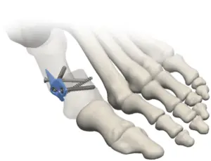
- The M.I.B. assembly allows for simultaneous correction in the frontal, transverse, and sagittal planes by utilizing a transverse osteotomy
- Multi-directional compression and stabilization of the osteotomy is achieved by using 2.4mm distal locking screws in conjunction with two anti-rotational, crossing, interfrag screws
- The titanium plate masks the osteotomy for minimal, medial palpability through the transition between the distal shoulder and proximal intramedullary spade
- All M.I.B. system instrumentation and implants are contained in a single, small, autoclavable tray
MINIMALLY INVASIVE BUNION (M.I.B.) PLATING SYSTEM
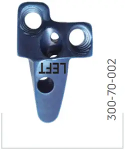
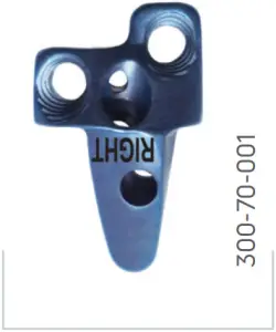
Left M.I.B. Plate Right M.I.B. Plate
| System Screws | Tiger Cannulated | Gridlock Locking | Gridlock Non-Locking |
| Diameter | 2.4mm | 2.4mm | 2.4mm |
| Lengths* | 16 – 32mm | 14 – 24mm | 14 – 24mm |
*Screw lengths offered in 2mm increments
![]()
SURGICAL TECHNIQUE
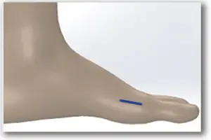
STEP 1: Make a 2cm longitudinal, medial incision over the intended osteotomy site (incision size may vary depending upon surgeon preference and patient anatomy; 2cm incision recommended to provide adequate access for hardware while limiting final incision size).
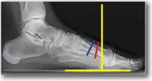
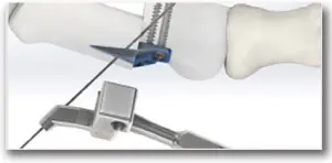
STEP 2: Create transverse osteotomy through the metatarsal using a saw.Angle the osteotomy towards the 5th metatarsal head while splitting the difference of perpendicular to the long axis ofthe metatarsaland perpendicular to weight bearing surface. Split the difference of perpendicular to the long axis of the metatarsal (blue line) and perpendicular to the ground (yellow lines). Red line is orientation of osteotomy.
STEP 3: Assemble the plate construct by securing the desired M.I.B. Plate to the appropriate Plate Placement Guide using the M.I.B. Threaded Drill Guides.
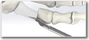
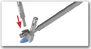
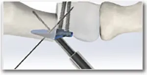
STEP 4: Manually, or with the use of a small mallet, broach at the apex of the deformity in the proximal medullary canal while distracting the distal bone segment.

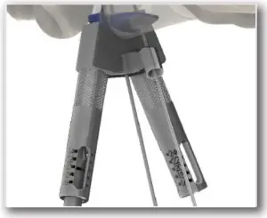
STEP 5: Remove the broach, and using the plate assembly, insert the M.I.B. Plate into the broached region and temporarily secure placement utilizing two K-wires inserted to the correct length through the wire guide holes in the assembly.
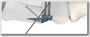
STEP 6: Pilot drill through one of the M.I.B. Threaded Drill Guides for distal screw placement. Utilize the calibrations on the M.I.B. Threaded Drill Guide and 2.4mm Calibrated Drill Bit to determine the necessary screw length or if calibrated measuring is not preferred or possible, then the depth gauge may be utilized.
STEP7: Remove M.I.B.Threaded Drill Guide and insert appropriate length Gridlock 2.4mm Locking Screw into the pilot hole through the Plate Placement Guide using the 2.4mm/3.0mm Gridlock Driver Bit.
STEP 8: Repeat steps 6 and 7 for remaining distal screw.
STEP 9: Remove Distal Placement K-wire from the plate assembly and remove the Plate Placement Guide assembly by sliding back over the remaining Proximal Placement K-wire.
STEP 10: Insert the M.I.B. Interfrag Drill Guide into the remaining plate screw hole and pilot drill for an interfrag screw.Utilize the calibrations on the M.I.B. Interfrag Drill Guide and 2.4mm Calibrated Drill Bit, or the provided Depth Gauge to determine the necessary screw length.
STEP11: Remove the M.I.B. Interfrag Drill Guide and insert appropriate length solid core, Gridlock 2.4mm Non-Locking Screw into pilot hole using the 2.4mm/3.0mm Gridlock Driver Bit. OPTIONAL: A Tiger 2.4mm Cannulated Screw may be utilized here instead.
STEP 12: Slide the 2.4mm Countersink over the remaining K-wire until the 2.4mm Countersink tip contacts bone. Rotate the 2.4mm Countersink back and forth to create the necessary recess in the bone.
STEP 13: Measure for the necessary screw length by examining the end of the K-wire in relation to the marks on the Cannulated Depth Gauge.

STEP 14: Slide the appropriate length Tiger 2.4mm Cannulated Screw over the K-wire and insert the screw using the 2.0/2.4mm Cannulated Driver Bit until desired compression is achieved.
STEP 15: Remove and discard K-wire.

STEP 16: Close surgical site and skin per standard surgical technique.
FDA cleared 510(k) K172178.Trilliant products are made in the U.S.A.
![]()
T 800.495.2919 F 877.778.3864727 North Shepherd Drive, Suite 100 | Houston, TX 77007 | U.S.A.djoglobal.com
Copyright © 2021 by DJO, LLC900-00-088 Rev E
Individual results may vary. DJO, LLC is a manufacturer of orthopedic implants and does not practice medicine. Only an orthopedic, or foot and ankle surgeon can determine what treatment is appropriate.The contents of this document do not constitute medical, legal, or any other type of professional advice.This material is intended for the sole use and benefit of the DJO, LLC sales force and physicians.It is not to be redistributed, duplicated, or disclosed without the express written consent of DJO, LLC. For more information on risks, warnings, and possible adverse side effects refer to the Instructions for Use provided with the device.
References
[xyz-ips snippet=”download-snippet”]