
DJO TRILLIANT Gridlock Ankle Plating System Instructions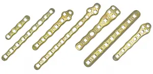
The Gridlock Ankle Plating System consists of titanium plates, screws, and instrumentation for applications in the bones of the ankle including trauma and corrective surgical procedures.
FEATURES
- Screw options include 2.7, 3.5, and 4.0mm low profile solid core locking and non-locking screws, 4.0mm cannulated screws, and syndesmotic screws with a tapered core designed for greater strength
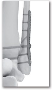
- Minimized post operative plate palpability with vanishing edge design and limited surface contact with Gridlock technology
- Triple relief hole configuration design intended to increase plate malleability while maintaining plate strength
- Skive feature on proximal and distal edges to aid in plate placement
- Low profile, pre-bent, pre-contoured specialty plates.
GRIDLOCK ANKLE PLATING SYSTEM
- Buttress Plate

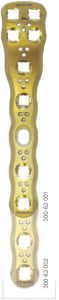
- VL Distal Fibula Plate
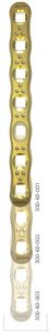
- VL Fibula Plates
- Right/Left Contoured VL Fibula Plates
- Universal Contoured VL Fibula Plates
- 1/3 Tubular Plates
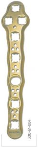
- VLTibia Plates


SURGICAL TECHNIQUE
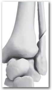

- STEP 1: Identify, expose, and prepare the surgical site.
- STEP 2: Reduce the fracture, osteotomy, or fusion site.
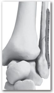
- STEP 3: Select appropriate plate for fixation of fracture, osteotomy, or fusion. Though plates are precontoured, slight adjustments may be required and made using the plate bending instruments. Warning: Excessive or multiple plate bends may cause weakness in the plate.
- STEP 4: Apply the plate to the prepared site. The plate may be temporarily fixated with either olive wires or K-wires.
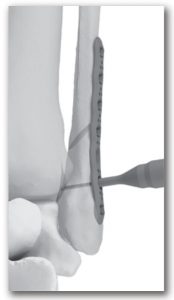
- STEP 5: Select desired screw diameter and the corresponding pilot drill.
- STEP 6: Select the corresponding drill guide and place it into the first plate hole nearest the fracture line or osteotomy site.
- STEP 7: Drill the pilot hole with the corresponding drill diameter at the desired angle of approach through the drill guide. Note: It is recommended to irrigate during pilot drilling.
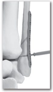
- STEP 8: Insert the depth gauge into the pilot hole to determine screw length. Note: Gridlock ankle screw length is measured tip to tip. There are no threads on the distal end of the screw.
- STEP 9: Select the desired screw length and type. Insert screw into the pilot hole and drive into position rotating clockwise with the driver.
- STEP 10: Repeat steps 5-9 until all screw holes are filled. When placing additional screws, make sure placement does not interfere with other screws.Note: The syndesmotic holes are not intended for locking screws.
Individual results may vary. DJO, LLC is a manufacturer of orthopedic implants and does not practice medicine. Only an orthopedic, or foot and ankle surgeon can determine what treatment is appropriate. The contents of this document do not constitute medical, legal, or any other type of professional advice. This material is intended for the sole use and benefit of the DJO, LLC sales force and physicians.It is not to be redistributed, duplicated, or disclosed without the express written consent of DJO, LLC. For more information on risks, warnings, and possible adverse side effects refer to the Instructions for Use provided with the device.
T 800.495.2919 F 877.778.3864727 North Shepherd Drive, Suite 100 I Houston, TX 77007 I U.S.A.djoglobal.comCopyright © 2021 by DJO, LLC900-00-054 Rev K

References
[xyz-ips snippet=”download-snippet”]