Instruction Manual
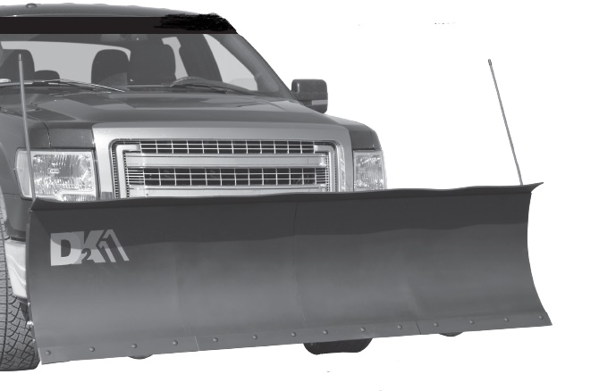
DK2 Snowplow Instruction Manual
STOP!
Questions, problems, missing parts? Do not return to your retailer.Please call our customer service department at: 1(888) 277-6960. Our customer service staff are ready to provide assistance. If a part is damaged or missing, replacement parts can be shipped from our facility. For immediate help with assembly, or for additional product information, call our North American toll-free number: 1(888) 277-6960.C Save this manual You will need this manual for safety instructions, operating procedures, and warranty. Put it and the original sales invoice in a safe, dry place for future reference.
THANK YOU FOR PURCHASING A DK2 PLOW!
This snowplow is designed for residential snow removal.Please remember to use the right tool for the job at hand. Avoid overtaxing your snowplow.Take care using it to clear thick, heavy (wet) snow.Your DK2 snowplow not intended to clear the snow deposits created by large municipal or commercial snowplows, which contain heavy compacted, frozenlumps of snow and ice, and could damage the plow and vehicle.If you have any questions or problems with your Detail K2 snowplow, includingset-up difficulties, broken or missing parts, etc.), do not return product to the store.Please call our toll-free service line at 1(888) 277-6960 to speak to a technician.Detail K2 Inc., 1080 Clay Avenue Unit #2, Burlington, Ontario, L7L 0A1 CanadaWe reserve the right to change product design and specifications without notice orobligation
IMPORTANT SAFE OPERATING PRACTICES ENGLISH
![]() IMPORTANT: Read safety rules and instructions carefully before operatingthis equipment.
IMPORTANT: Read safety rules and instructions carefully before operatingthis equipment.
![]() CAUTION: SAFETY FIRST— Read this manual carefully before operatingyour snowplow. We recommend that you read this manual completely so thatyou are fully aware of all important safety recommendations. Record your serialnumber.
CAUTION: SAFETY FIRST— Read this manual carefully before operatingyour snowplow. We recommend that you read this manual completely so thatyou are fully aware of all important safety recommendations. Record your serialnumber.
![]() DANGER: This equipment was built to be operated according to the rulesfor safe operation in this manual. As with any type of power equipment,carelessness or error on the part of the operator can result in serious injury.This machine is capable of amputating hands and feet. Failure to observe thefollowing safety instructions could result in serious injury or death.
DANGER: This equipment was built to be operated according to the rulesfor safe operation in this manual. As with any type of power equipment,carelessness or error on the part of the operator can result in serious injury.This machine is capable of amputating hands and feet. Failure to observe thefollowing safety instructions could result in serious injury or death.
To use this equipment properly, you must observe the safety regulations, theassembly instructions and the operating instructions to be found in this manual. Allpersons who use and service the snowplow must be informed about its potentialhazards and must be acquainted with this manual. Children should be supervisedat all times if they are in the area in which the snowplow is being used. It is alsoimperative that you observe the accident prevention regulations in force in yourarea. The same applies for general rules of occupational health and safety.
CALIFORNIA PROPOSITION 65
WARNING: This product can expose you to chemicals including DEHP, whichis known to the State of California to cause cancer and birth defects or otherreproductive harm. For more information go to www.P65Warnings.ca.gov.
GENERAL
- Read your owner’s manual carefully. Get to know your snowplow and familiarizeyourself with its applications and limitations.
- Use the snowplow according to the guidelines in this manual. Do not abuse it orforce it to do a job for which it was not designed.
- Use only original equipment parts and accessories. Consult the owner’smanual. The use of incorrect accessories may produce unforeseen hazards.
![]() WARNING: Make no attempt to assemble and operate the snowplow untilyou have thoroughly read this manual and completely understood its contents.Operating your DK2 snowplow improperly can result in serious personal injuryand/or damage to both plow and vehicle. Since Detail K2 Inc. does not completeits assembly or installation, we cannot be held responsible for any personalinjury or damages that product misuse may produce.
WARNING: Make no attempt to assemble and operate the snowplow untilyou have thoroughly read this manual and completely understood its contents.Operating your DK2 snowplow improperly can result in serious personal injuryand/or damage to both plow and vehicle. Since Detail K2 Inc. does not completeits assembly or installation, we cannot be held responsible for any personalinjury or damages that product misuse may produce.
PERSONAL SAFETY
- For safety, keep children and pets at a distance from the plow and the operatingarea.
![]() DANGER! Sitting or riding on the snowplow is extremely dangerous. This couldinflict serious injury.
DANGER! Sitting or riding on the snowplow is extremely dangerous. This couldinflict serious injury.
![]() WARNING! Never stand between the vehicle and the blade nor stand within3 m (10 feet) of a blade in motion. Moving or falling blades can cause seriouspersonal harm.
WARNING! Never stand between the vehicle and the blade nor stand within3 m (10 feet) of a blade in motion. Moving or falling blades can cause seriouspersonal harm.
ENGLISH IMPORTANT SAFE OPERATING PRACTICES
WARNING! At all times, keep your hands and feet clear of the blade and ![]() winch
winch
WARNING! When mounting or removing the snowplow, keep hands and feetclear of the blade, mounting assembly and winch. Moving or falling assemblies![]() have a potential to cause personal injury. Never use your finger to checkalignment. Moving or falling assemblies could crush your finger.
have a potential to cause personal injury. Never use your finger to checkalignment. Moving or falling assemblies could crush your finger.
CAUTION: Transport speed should never exceed 70 km/h (45 mph). Adversetravel conditions may dictate a further speed reduction. Must use appropriate![]() driving lights
driving lights
- Wear a seat belt when plowing snow. Hidden obstacles could make the vehiclestop suddenly, resulting in personal injury.
- Put the vehicle in park or into gear and remove the ignition key to preventothers from starting the vehicle when installing or servicing the plow.
- Dress properly. Do not wear loose clothing or jewellery. Keep your hair, clothing,and gloves away from moving parts. Loose clothes, jewellery or long hair canbe caught in moving parts. For warmth, wear layers of clothing, taking off layersas you get warmer.
- Wear safety goggles when working under the hood of the vehicle. for eyeprotection from battery acid, gasoline, dirt and dust. Everyday eyeglasses haveonly impact resistance lenses. They are not safety glasses.
- For work connected with the vehicle , avoid touching any hot surfaces such asthe engine, radiator, hoses and exhaust pipes.
- Always have a fire extinguisher , rated BC, handy for flammable liquid andelectrical fires.
- Do not plow snow with your head out the window. Sudden stops or protrudingobstacles could result in personal injury.
- The driver only should be in the vehicle when plowing snow.
SNOW PLOW
- Maintain the snowplow and keep it clean and lubricated. This applies evenwhen the unit is not in use so as to avoid corrosion. In the off season, inspectthe unit and apply corrosion-resistant paint to any areas that show corrosion toprevent further damage. If stored outside, cover the winch assembly.
- Carefully inspect your snowplow before every use. Particularly check thealignment of moving parts and tighten any loose screws and bolts.
- This unit is not intended for commercial use.
WARNING! Carefully inspect all snowplow components and bolts forlooseness, wear and damage when mounting or removing the unit and before![]() transporting it.
transporting it.
4. With heavier full-sized vehicles, mainly through momentum, it may be easier todamage the plow assembly. Cautious use will help extend your years of troublefreeservice.
VEHICLE5. Do not attempt plowing snow at speeds above 15 km/h(10 mph). Driving at speeds above 15 km/h (10 mph) with the plow attachedreduces the cool air intake and may cause your vehicle engine to overheat.
IMPORTANT SAFE OPERATING PRACTICES
6. Do not overload the vehicle. Take into account the loaded vehicle weight,including the entire snowplow assembly, all accessories, driver and passenger,fluids, and cargo. This weight is not to exceed the front/rear Gross AxleWeight Rating (GAWR), and total Gross Vehicle Weight Rating (GVWR). Thespecific ratings for your vehicle are noted on the safety compliance certificationlabel attached to the driver’s side door opening. Rear ballast weight may benecessary to prevent exceeding the front GAWR.
![]() CAUTION: The installation of a snowplow may have a bearing on the warrantyfor your vehicle. For more information, please carefully consult your vehicle’sowner’s manual or your vehicle dealer.
CAUTION: The installation of a snowplow may have a bearing on the warrantyfor your vehicle. For more information, please carefully consult your vehicle’sowner’s manual or your vehicle dealer.
CAUTION: The installation of a snowplow may have a bearing on the warrantyfor your vehicle. For more information, please carefully consult your vehicle’sowner’s manual or your vehicle dealer.
DRIVING
![]() CAUTION: Always be certain the quick-mount locking plates on your customfront mount are secured. If the plow is insecurely attached to the mount, it willlikely pull away from the vehicle, fall off and cause significant damageand/or injury.
CAUTION: Always be certain the quick-mount locking plates on your customfront mount are secured. If the plow is insecurely attached to the mount, it willlikely pull away from the vehicle, fall off and cause significant damageand/or injury.
- The use of lights is recommended, if not required by local regulations, whileplowing at night. Regular vehicle headlights will likely be obscured by the blade.
- Do not drive on public roads with the snowplow attached at the front of yourvehicle.
- Connect a safety hook when transporting the snowplow in the raised position.
- Do not attempt to change the blade position while traveling as you couldaccidentally suddenly lower the plow blade.
 WARNING! Consult local/ provincial laws regarding vehicle restrictions thatmight apply when the snowplow is not attached. Such restrictions may mandatethe removal of the mounting, lift frame, lift arm, winch mechanism or any otherprotruding elements mounted to the front of the vehicle during certain times ofthe year
PREPARATION
- Thoroughly inspect the area where the equipment is to be used. Make yourselffamiliar with the terrain you are plowing and avoid all obstacles.
- Remove all foreign objects such as doormats, newspapers, sleds, boards,wires, and other items.
- Before use, ensure that the plow is attached to your custom front mount andsafely secure the quick mount locking plates.
- Stay away from any obstacles. Familiarize yourself with the area and potentialdifficulties before plowing.
- Never attempt to make any adjustments while vehicle is running, except wherespecifically recommended in the operator’s manual(s).
- Exercise caution when changing direction and while operating on slopes.
- During continuous snowfalls, plow as snow builds to between 8 and 15 cm (3and 6”).
- Plan your snow plowing pattern to avoid discharge towards windows, walls,cars, etc. , thus avoiding possible property damage or personal injury. Neverdirect discharge at children, bystanders, and pets nor allow anyone in front ofthe plow.
IMPORTANT SAFE OPERATING PRACTICESOPERATING SAFETY
- Keep bystanders, helpers, pets and children at least 8 metres (25 feet) from theplow while it is in operation. Stop using it if anyone enters the area. Never allowchildren to operate it.
- Never allow anyone to ride on the plow in operation. Sitting on it may lead toserious injury.
- Do not overload plow capacity by attempting to clear snow at too fast a rate.
- Never operate this machine without good visibility or light. Extra lighting is highlyrecommended and, depending on the jurisdiction, may be required on roadwaysfor nighttime plowing.
- Never operate the plow at high transport speeds over 16 km/h (10 mph). Abovethis speed, vehicle engine overheating may also occur.
- Exercise caution , especially when operating in reverse.
- Do not operate without wearing adequate winter outer garments. Do not wearjewelery, long scarves or other loose clothing which could become entangled inmoving parts. Wear footwear which will improve footing on slippery surfaces.
WARNING: Restrict the use of this plow to persons who read, understandfollow the warnings and instructions in this manual and on the machine.![]()
WARNING: The warnings, cautions, and instructions detailed in this manualcannot cover all possible conditions and situations that occur. It must be![]() understood by the operator that COMMON SENSE AND CAUTION AREFACTORS that cannot be built into this product, but MUST BE SUPPLIED BYTHE OPERATOR.
understood by the operator that COMMON SENSE AND CAUTION AREFACTORS that cannot be built into this product, but MUST BE SUPPLIED BYTHE OPERATOR.
WARNING: DO NOT OPERATE this equipment until it has been assembledand set up according to the instructions in “Snowplow Assembly”. Read and![]() follow all safety rules within this Instruction Manual. Failure to do may result inserious personal injury.
follow all safety rules within this Instruction Manual. Failure to do may result inserious personal injury.
SPECIFICATIONS
- Blade dimensions:○○ SUMM8826: 2.2 m wide x 66 cm high (88 inch x 26 inch)○○ STOR8422: 2.1 m wide x 56 cm high (84 inch x 22 inch)○○ RAMP8219 2.08 m wide x 48 cm high (82 inch x 19 inch)
- Fits most light trucks and SUVs
- Easy attachment: slides into your custom mount
- Electric winch or actuator with wired remote control for easy up and downsnow control
- 3 locking angles: to either side or straight ahead
- Steel construction powder coated with UV-protected paint
- Castors allow attachment and removal in seconds, plus roll-away storage
- Comes with:○○ 3,000 lb. wireless winch or wireless actuator○○ hardened steel cutting edge○○ rubber snow deflector○○ polymer plow markers○○ skid shoes
- ISO 9001 certified manufacturer
- Assembled weight :○○ SUMM8826: 134.26 kg (296 lb.)○○ SUMM8826 ELT: 152.41 kg (336 lb.)○○ STOR8422: 128.37 kg (283 lb.)○○ STOR8422 ELT: 146.51 kg (323 lb.)○○ RAMP8219: 120.2 kg (265 lb.)○○ RAMP8219 ELT: 138.34 kg (305 lb.)
- 1 year warranty
VEHICLE REQUIREMENTS
![]() WARNING! Always inspect snowplow components, connections, and fastenersfor wear or damage every time you attach or detach the snowplow. Worn ordamaged components may allow the snowplow to fail without warning, resultingin serious injury or vehicle damage.
WARNING! Always inspect snowplow components, connections, and fastenersfor wear or damage every time you attach or detach the snowplow. Worn ordamaged components may allow the snowplow to fail without warning, resultingin serious injury or vehicle damage.
VEHICLE RECOMMENDATIONSThe vehicle with the snowplow installed must comply with applicable motor vehiclesafety standards and with the vehicle manufacturer’s stated gross vehicle and axleweight ratings (found on the driver’s side door corner post of the vehicle) as wellas the front and rear weight distribution ratio. In some cases, rear ballast may berequired to comply with these requirements. (See Ballast Requirements below.)The weights of front seat occupants can be adjusted above 136 kg (300 lb.), butthe total vehicle weight with snowplow must not exceed vehicle GVWR or GAWR.Installation, modification and addition of accessories must comply withmanufacturers’ and regulators’ published recommendations and instructions.Available capacity decreases as the vehicle is loaded with cargo or other truckequipment or as snowplow accessories are installed.If there is uncertainty as to whether available capacity exists, the actual vehicle asconfigured must be weighed.BALLAST REQUIREMENTSBecause of the front/rear axle weight ratio, ballast (additional weight) is importantin qualifying vehicles for snowplow eligibility. Rear ballast must be used whennecessary to remain in compliance with axle ratings and ratios as specified by thevehicle manufacturer.Ballast, if required, must be retained correctly behind the rear axle, distributedevenly across the width of the vehicle. The weight of the ballast retainer should beconsidered part of the ballast weight. We recommend sand bags for ballast.INSTALLING A SNOWPLOW MOUNT TO YOUR VEHICLETo install the custom mount for your DK2 snow plow you can reference the custommount installation manual that is included with your custom front mount. For moreinformation call DK2 at 1-888-277-6960 or visit us at www.detailk2.com.
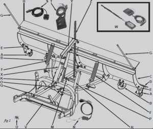
STANDARD PLOW FUNCTIONAL DESCRIPTION

| I.D. Name | Function |
| A Fixed castor (2) | carries the weight of the plow during mounting, dismounting, and storage |
| B Skid shoe (2) | holds the scraper edge at a set height during plowing |
| C Blade | pushes and channels the snow away |
| D Scraper | provides a hardened steel cutting edge for long life |
| E Castor height adjustment pin | allows castors to be set at vehicle height for mounting /dismounting and retracted forplowing |
| F Trip spring (2) | allows blade to trip forward when hitting obstructions, absorbing shock to plow, vehicle, andoperator |
| G Marker (2) | brightly coloured to locate the extreme outside corners of blade in blowing snow or lowvisibility |
| H Rubber snow deflector | reduces snow blown over top of blade onto vehicle windshield |
| I Blade angle locking handle | operates blade angle locking pin to allow blade to move between 22 and 38 degrees right orleft, or straight across |
| J Winch | raises and lowers the blade |
| K Main frame | Holds the winch and connects to the a-frame and your custom mount |
| Winch strap
|
connects the winch to the A-frame |
ELITE SERIES PLOW FUNCTIONAL DESCRIPTION

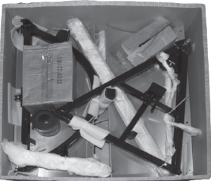
SNOWPLOW ASSEMBLY
- Carefully unpack the carton (fig.3), accounting for each of the parts by referringto the function picture, parts list and schematic drawing (see page En.23)

- Continue to refer to the parts list and exploded drawing while assembling theplow.
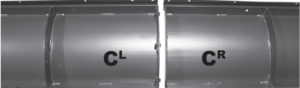
- Using the grade 8 bolts and nuts included, bolt together the two halves of thesnowplow blade (fig.4, CL and CR, below).
4. Attach the scraper (three pieces, a long, SL, and two short ones: SS; fig.5, atright) to the front lower edge of the full blade using 25 mm (1”) x M10 grade 8carriage bolts, 10 mm washers, and M10 Nylock nuts (fig.6). The long piece ofthe scraper overlaps both halves of the blade. The shorter piece fills in the rest. The carriage bolts areinserted so that their domed caps are at the front ofscraper, which lies on the lower front (concave side)edge of the blade. The nuts screw on from the back(convex) side of the plow blade. Tighten the nuts.Attach the two skid shoe holders (fig.7) to the
bottom of thelower cross rib on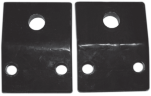 the back of theplow blade. They should be attached so thatthey are cupped upwards, the ends of theholders with the two holes angled slightlywhen the blade stands vertically and the endhaving the single large hole alignedhorizontally so that the shoes are vertical. Toattach each, use 2 M12 x 32 mm gr.8 hex head bolts inserted from below, and 2 M12 Nylock nuts threaded on from thetop to attach it to the cross rib.
5. If not already done, thread an M18 nut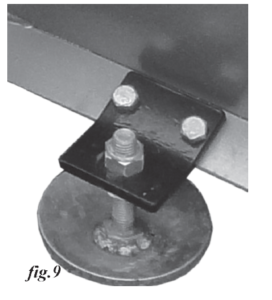 onto the shaft of each skid shoe (fig.8).

Assuming the blade assembly is held in avertical position, insert the skid shoes intothe skid shoe holders from below. Holdthem in place with a Nylock nut on top ofeach (fig.9). Temporarily set the shoes sothey hold the blade scraper about 1 cm(1/2 inch) above the surface. This is thenormal setting for paved surfaces, but youcan vary the height according toconditions.
SNOWPLOW ASSEMBLY
6. Assemble the D frame (fig.10) on top of the A frame (fig. 11). With the rounded portion of the D frame held so it slides under the angle bracket (a, fig.10) on topof the A frame and the centre hole engages the angle locking pin (12, fig.10),connect the two frames using the pivot bolt. This is a 75 mm (2.95”) M6 gr.8 hexhead bolt with a 16 mm washer (8, fig.10), inserted from below the hole in theapex of the “A” of the A frame, through the pivot bolt sleeve. It goes up througha hole in the centre of the straight side of the “D” in the D frame. Hold this inplace with an M16 Nylock nut. (fig.12, below)
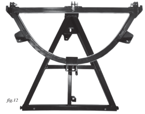
7. Attach the main frame to the A frame using the two frame pins (7, fig 13). Lockthe pins into the A frame with an M8 x 52 mm gr.8 hex head bolt (42, fig 13)inserted through an 8 mm washer, then the top of the frame at each end andsecured with M8 nylock nuts.8. If not already attached, bolt the winch to the top of the main frame with 4 M8 x30 mm gr 8 hex head bolts, 8 mm washers, and M8 Nylock nuts; the bolts beinginserted from the front through the winch base9. Remove the gr.8 U-bolt from the top of the A frame, attach the lower end of thewinch strap to it and re-attach. The strap should feed over top of the barrel ofthe winch toward the front and down to the attachment point on the A frame.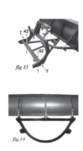 (fig.13). The U-bolt should not be tightened fully. It should have a little play.10. Dis-regard steps 8 and 9 if using the DK2 Elite electric actuator kit. For help withactuator kit installation, visit https://www.dk2snowplows.com/faq; or call our tollfree number, 1(888) 277-6960.11. Align the D frame’s 3 attachment points with the two vertical centre ribs of eachplow blade panel as well as the double, joined vertical ribs in the middle of theplow (fig.14). Insert clevis pins through each attachment point and the verticalribs on the back of the blade. Secure the clevis pins (23, fig.15) in place withcotter pins and bend them so they remain in place.12. If not already done, attach the 2 flip-down fixed castors to the inside edge of thelast ribs on each end of the snow plow blade by bolting them to the rib. Whenplowing make sure to flip castors up and insert the pin to avoid damage whileplowing.13. If not already done, attach the swivel castor to the castor holder shaft andslide it from below into the shaft holder in the A frame. Lock it with the castor
SNOWPLOW ASSEMBLY
adjustment pin so that the frame is horizontal and the blade vertical.14. Hook the trip springs (18, fig.15) into the holes in the top cross rib at the back ofeach plow blade panel (37/38h, fig.15). Attach the springs to the angle plates onthe D frame (5a, fig.15) using for each an M12 gr.8 eyebolt (17, fig.15), M12 nut,2 12 mm washers and an M12 Nylock nut.15. Tighten the Nylock nuts to the point where the springs are just tight. Then turn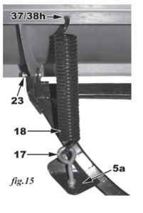 the Nylock nut, shortening the take-up by 6 mm (1/4 inch) further so the springsopen slightly. Snug up the inner M12 nut to hold the assembly tight. Assemblethe blade angle locking handle with knob to the A frame so that it operates thespring-loaded angle lock pin in the bracket on top of the A frame smoothly. Boltthe end of the handle opposite the knob (16, fig.16) to the eye in the small tab inthe A frame’s centre cross piece (6t, fig.16) with an M8 x 25 mm gr.8 bolt (48,fig.16) and 2 x 8 mm washers. Secure with an 8 mmNy lock nut. Bolt the handleto the hole in the angle lock pin with an M8 x 35 mm gr.8 bolt (49, fig.16) and 2x 8 mm washers. Secure with an 8 mmNy lock nut.16. Attach the snow deflector to the top flange of the plow. Place the deflectorrubber along the top angle of the plow blade. On top of that place the short andlong metal deflector battens. Bolt them into place with 7 M10 x 25 mm carriagebolts down through all but the two end holes. In the end two holes, insert the threaded ends of the two snowplow marker wands. Secure all with 9 x M10Ny lock nuts threaded on from below the flange.17. Using two bolts and nuts, attach the light bar with the two lights to the top edgeof the winch support tower.18. Connect the safety chain to the bottom of the winch mounting plate with thethreaded quick link. During transportation with the plow blade raised, theclip hook should fasten to the hole in the angled tab just behind the strap
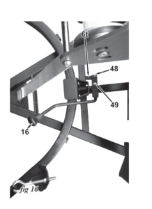 attachment point in the apex of the A frame, preventing the plow blade fromfalling should anything fail.19. It is normal for the whole assembly to rock back and forth when mounted,with the plow blade moving side to side from 20 to 25 cm (8 to 10 in.) Thiscompensates for differences in terrain between the surface the plow rides onand what the vehicle is riding on. This flexibility should not be reduced.
ELITE SERIES ACTUATOR ASSEMBLY
- see fig.17
- Attach the Actuator mounting bracket, part #59 to the main frame.
- Using hardware #64 Hex bolt (1/2”-13 x 3”, bolt part #58 Actuator pivot arm, to#59, the Actuator mounting bracket, through the center hole.
- Part #66 Actuator safety pin, goes through the end of part number 58, theActuator pivot arm.
- Use hardware #63, Hex bolt (1/2”-13 x 2-1/2”) to mount #60, the Electricactuator to #58, the Actuator pivot arm.
- Insert the Lifting chain, #61, through the Actuator safety pin, #66and fasten the top to #58,. the Actuator pivot arm.
- Using the U-Bolt (#10), inserted in the A-frame (#5), fasten the otherend of the chain.

SNOWPLOW ASSEMBLYELECTRICAL INSTALLATION
![]() CAUTION! Before working on the wiring, winch or activator in your vehicle,disconnect the battery and any other power sources.
CAUTION! Before working on the wiring, winch or activator in your vehicle,disconnect the battery and any other power sources.
![]() CAUTION! For work connected with the vehicle, avoid touching any hotsurfaces such as the engine, radiator, hoses and exhaust pipes.
CAUTION! For work connected with the vehicle, avoid touching any hotsurfaces such as the engine, radiator, hoses and exhaust pipes.
WINCH LEADS
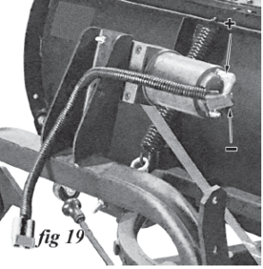
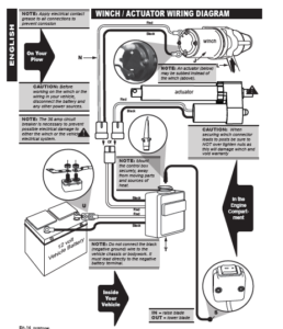
- Connect the winch leads (fig.18), tagged “To Motor”, to the contacts on thewinch motor as shown (fig.19). Be sure therubber caps cover the connections well toprevent water entry. The red lead should beconnected to the positive (+ upper) terminalon the winch, and the black lead connected tothe negative (- lower) winch terminal.
- Lay the red and black leads down alongthe winch support tower, using nylon ties tosecure them in place.
- Use a nylon tieetain the short cable leash on the blue 2” connector plug cap to the to r winch support tower.

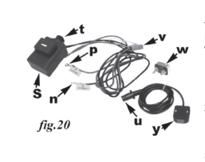
CONTROL BOXThe control box includes a transponder that can connect it wirelessly to a wirelessremote control switch (optional at extra cost). There is also a hard-wired manualwinch control switch (y, fig.20) included to operate your plow.
- Attach the control box (s,fig.20) to the vehicle in the engine compartment. Mountit securely, away from moving parts and sources of heat. Take into account theamount of wire available to reach the vehicle battery and the amount of wireavailable to connect to the winch leads.
- Run the red (p, fig.20) and black wires (n, fig.20) attached to the blue 2 inchconnector plug (v, fig.20) forward to a point outside the front of the vehicle nearthe custom mount, where the plug can easily be connected to the plow lead.Leave some slack.
- Run the red and black wires marked “To Battery” to the battery. The black wire
- should be connected directly to the negative terminal of the battery.
 connector plug (v, fig.20) forward to a point outside the front of the vehicle nearthe custom mount, where the plug can easily be connected to the plow lead.Leave some slack.
NOTE: Do not connect the black (negative ground) wire to the vehicle chassisor bodywork. It must lead directly to the negative battery terminal.
4. The red wire must be connected to the positive terminal of the battery with anintervening in-line 35 amp circuit breaker (w, fig.20) or fuse. The 35 amp circuitbreaker is necessary to prevent possible electrical damage to either the winchor the vehicle’s electrical system.
![]() WARNING: If there is a DK2 wireless controller in the immediate vicinity ofthe control box, it can operate your plow’s winch. Be aware there is danger ofunexpected movement of the winch and blade.
WARNING: If there is a DK2 wireless controller in the immediate vicinity ofthe control box, it can operate your plow’s winch. Be aware there is danger ofunexpected movement of the winch and blade.
5. Run the hard-wired control lead so that the switch (y, fig.20) goes into the cabof the vehicle and the plug (u, fig.19) connects to the socket in the top of thecontrol box (t, fig.20).
![]() WARNING: Never stand between the vehicle and the blade nor stand within3 m (10 feet) of a blade in motion. Moving or falling blades can cause seriouspersonal harm.
WARNING: Never stand between the vehicle and the blade nor stand within3 m (10 feet) of a blade in motion. Moving or falling blades can cause seriouspersonal harm.
OPERATING PROCEDURES
OPTIONAL LIGHT KITWiring for the optional snowplow lights must be run and connected separately,either connected to the vehicle auxiliary lighting or separately switched. Switchingfor the light bar is at the top of the winch support tower.
![]() CAUTION! Be sure that the snowplow lights are properly aimed when thesnowplow is mounted on the vehicle, since its weight and the weight of anyballast will affect the way the vehicle sits on the road.
CAUTION! Be sure that the snowplow lights are properly aimed when thesnowplow is mounted on the vehicle, since its weight and the weight of anyballast will affect the way the vehicle sits on the road.
OPERATION
![]() WARNING!
WARNING!
- Always inspect snowplow components, connections, and fasteners for wearor damage every time you attach or detach the snowplow. Worn or damagedcomponents may allow the snowplow to fail without warning, resulting inserious injury or vehicle damage.
- Before plowing the first time, be sure all fixtures, connections, and parts aretight and properly aligned.
- Lift the plow using the control for the winch.
- The plow angle can now be adjusted using the handle to release the angle lockpin from the holes in the D frame. Move the handle away from the blade towardthe front of the vehicle and then rotate the blade and D frame. The plow can bepositioned at an angle to the left and to the right of the line of travel or straightacross the front of the vehicle. Releasing the handle will allow the spring-loadedpin to fall into the appropriate hole in the back of the D frame to hold its position
- After the first use, it is recommended that all bolts in the assembly are checkedand re-tightened.
- 2-wheel-drive vehicles and some others may have lower clearance. This willlikely be further reduced by the front mount as well as the added weight of theplow. You may feel it helpful to adding spring height or increasing tire size toprovide extra clearance needed. Though plowing ability will not be affected,because of its extension ahead of the front wheels, there is an increasedlikelihood of catching the plow assembly on raised or uneven surfaces.
- This plow was intended to ease the clearance of newly fallen snow. TheDK2 Snow Plow is not intended to clear the snow deposits created by largemunicipal or commercial snowplows, which contain heavy compacted, frozenlumps of snow and ice, and could damage the plow and vehicle. Do not use itfor removing or pushing excessive amounts of snow, nor for ice, sand or gravel.
- Mainly because of the design of the blade elevation and lowering mechanism,back-dragging with this unit is not practical nor recommended.
![]() WARNING! With heavier, full-sized vehicles, mainly through momentum, itmay be easier to damage the plow assembly. Cautious use will help extend youryears of trouble-free service.
WARNING! With heavier, full-sized vehicles, mainly through momentum, itmay be easier to damage the plow assembly. Cautious use will help extend youryears of trouble-free service.
PLOWING INSTRUCTIONSThe DK2 Snow Plow is intended for light personal use. It will effectively removesnow from parking lots, lanes, and driveways.To ensure long life for your snow plow, please observe thesefundamental instructions and notes:
- Before beginning to plow, always check the main frame and the custom mountare correctly installed and secured using the two quick mount locking plates.Pull strongly forward on the plow. It should not move out of the front mount.
- In heavy, continuing snowfalls, do not delay; plow regularly every 8 to 15 cm(3 to 6 inches) of snow accumulation. With heavy, wet snow increase the
OPERATION
frequency.
- To plow higher snow drifts, raise the blade and remove layer of snow from thetop, lowering the blade by degrees on successive passes until the full depth isremoved.
- Do not allow the snow to become icy. Plowing immediately after each snowfallreduces the possibility the plow be used to break through ice.
- Be familiar with the area being plowed or have someone who is familiar pointout hazards. Exercise caution because hidden obstacles can inflict severedamage to both plow and vehicle.
- Keep a distance of a metre (3 ft.) from obstacles such as building walls,telephone poles, and gates because the vehicle may slip sideways and causethe plow to contact them.
- Ramming into a pile of snow will void your warranty and may cause damage toyour vehicle. This plow is not designed for ice blocks
- Do not attempt plowing snow at speeds above 15 km/h (10 mph). Faster mayoverload the unit or contribute to loss of control of the vehicle.
- Should the plow appear to hop when plowing, a reduction in speed isrecommended.
- The DK2 Snow Plow will, by design, trip forward if overloaded or on strikingan obstacle buried under the snow. The trip springs will then pull it back to thecorrect position. Before carrying on with caution, it is prudent to search out anyhidden obstacles.
- Before backing up, elevate the plow.
- Make it a practice to lower the blade to the ground every time the vehicle isparked.
- Do not leave the plow mounted on the vehicle between uses. It is easy toremove and re-attach.
- Do not let ice and snow build up on the winch. Clear it off frequently so theblade’s raising and lowering functions are not impeded. If stored outside, coverthe winch assembly.
- NOT DESIGNED FOR TRANSPORTATION ON PUBLIC ROADS. In mostjurisdictions, driving on highways with a plow attached to your vehicle requiresa lighting kit with turn signals as well as a safety retention chain to prevent theplow falling off the vehicle. Consult local regulations.
NOTE: Travelling at speeds above 15 km/h (10 mph) with a plow attachedobstructs the vehicle’s cool air intake and may cause engine overheating.
PLOWING LANESNOTE: Always begin the season plowing lanes as widely as you can. As theseason progresses, maintenance of lane width is easier if there is room to movethe subsequent snowfalls to.Procedure:
- Set the plow at an angle and move down the lane pushing the snow as closeas possible to the edge where the snow will be piled. Stay clear of any ditches,trees, buildings and other obstacles along the lane.
- When you reach the end of the lane, turn the vehicle around and return goingdown the other side of the lane, building up a second pile of snow, withoutchanging the angle of the plow.
- Run along the edges again, repeating this action and push the snow pile backincrementally further on each pass.
OPERATIONPLOWING PARKING LOTS
NOTE: Always begin the season plowing parking lots as widely on all sidesas you can. As the season progresses, maintenance of the width of the clearedarea is easier if there is more room to move the subsequent snowfalls to.
Procedure:
- As a rule, plow outward from the centre to one edge, then start again from thecentre and plow outward to the other side.
- Set the plow at 38° and drive down the centre of the parking lot to the far side.
- Stop before ramming the snow pile. Do not use the plow to stack the snow.
- Raise the plow blade.
- Reverse to the spot you started from.
- Plow an overlapping run parallel to the first.
- Raise the plow and continue in the same vein until one half of the parking lot iscleared.
- Get out and re-set the plow to 38° on the opposite side.
- Starting from the centre again, plow overlapping strips towards the other edgeof the parking lot.TIPS AND TRICKSStaking – Before snow even begins to fall, use stakes or wands to mark the edgesof places that need to be plowed, so that you can plow safely and neatly withoutdamaging the surrounding lawns and gardens. You can also mark hydrants, utilityboxes, gas meters, sewer vent pipes, etc.Drains – Through the season, ensure driveway drains remain clear andunobstructed, allowing snow an escape when it melts and less opportunity to refreeze.Speed – Plowing requires a safe, manageable speed limit, generally 15 km/h (10mph). Faster speed reduces your visibility by pushing or blowing snow onto thewindshield. If you hit an obstruction while plowing, the faster you’re going, thegreater the potential for personal injury or damage to equipment.Plan – Think of the season ahead when determining where to push snow. Startsnow banks back far enough that you have room for future snowfalls. Also, try topush snow away from buildings first, if possible.Stacking – As you near the far side of the lot, reduce speed and raise the blade toprevent scraping turf, as well as to help stack the snow. Do not stack snow with theblade set at an angle.Overloading – Allow the snow depth and water content to determine the width ofyour pass, or how much blade overlap you use for each pass. Move just enoughsnow with each pass to clear efficiently without overloading your equipment theplow or vehicle.Back-dragging – A common technique used in plowing driveways more thanthree car lengths long, back-dragging may not be practical with a winch operated,gravity-lowered plow. It involves driving forward to the starting point (usually thegarage door), dropping the blade, and pulling the snow back at least the length ofyour vehicle plus plow (about two car lengths). Repeat the process across the fullwidth of the driveway. Turn around and back into the area just back-dragged clearand push the snow to where the snow will be piled.Angle – A blade set at an angle is more effective for cutting and clearing hardpackedsnow.Traction – Ballast and snow chains, where allowed, are effective ways to increasetraction. Plowing deep snow requires a steady movement of the vehicle.
OPERATION
DETACHING THE SNOWPLOW
- Drive the vehicle to a clear area
- Raise the blade
- Lower the 2 flip-down castors and lower the rear support plate. Secure with pins
- Lower the blade
- Disconnect the electrical connections
- Remove the two locking plates from the custom mount
- Roll the plow to its storage place NOTE: After disconnection of the snowplow, always apply dielectric grease tothe electrical connectors and plugs, maintaining the protective coating on theterminals.NOTE: Cover the electrical connectors with the caps supplied and cover thewinch if stored outdoors.
- To re-attach the snowplow to the vehicle, reverse the process above.
TROUBLESHOOTINGDifficulties with your Detail K2 plow? Please refer to the troubleshooting tipsbelow. They are intended as a guide to assist in resolving some common technicalproblems and making helpful simple adjustments. For more assistance, pleasecontact, toll-free, the Detail K2 customer service department at 1(888) 277.6960.THE PLOW BLADE ROCKS OR TIPS FROM SIDE TO SIDE.
- It is normal for the whole assembly to rock back and forth when mounted on avehicle, with the plow blade moving side to side from 20 to 25 cm (8 to 10 in.)This compensates for differences in terrain between what the plow rides on andwhat the vehicle is riding on. It should not be reduced with shims or washers.
- If the rocking is excessive, check the pivot bolt to ensure that there is no morethan 6 mm (1/4”) of play. You can tighten the lock nut, if need be.
- The springs and eye bolts may not have enough tension. If the springs look asthough they are loose, loosen the inner nuts and re-tighten the Nylock nuts tothe point where the springs are just tight. Then turn the Nylock nut, shorteningthe take-up by 6 mm (1/4 inch) so the springs open slightly. Snug up the innerM12 nut to hold the assembly tight.
THE WINCH STRAP IS BROKEN OR BREAKING.
- Broken straps are often the result of a lack of free movement in the U-bolt, atthe point the strap is fastened to the A frame. Be sure that the lock nuts on theU-bolt allow it sufficient play.
- If the tie bar is bent, you will need to cut your winch strap off.
THE WINCH DOES NOT START, OR IT HESITATES.
CAUTION! Before working on the winch or the wiring in your vehicle,disconnect the battery and any other power sources.
- Check that the battery cable is securely connected to the battery’s negativeterminal. Do not connect the black (negative ground) wire to the vehicle chassisor bodywork. It must lead directly to the negative battery terminal.
- Check that the control box switch (in the engine compartment) is “ON”.
- Check that the winch contacts and the two 2” plug connectors are tight andfree of corrosion or dirt. Dielectric grease works well to protect electricalconnections.
DIRECTIONS ON THE CONTROLLER (i.e. blade lifts when ▼button is pressed and vice versa)
- Check that the red lead is connected to the positive (upper) terminal on thewinch, and the black lead connected to the negative (lower) winch terminal.
THE WIRING, CONTROL SWITCH OR CONTROL BOX AREHOT.
- Be sure that a circuit breaker has been installed between the red battery cableand the battery’s positive terminal. The breaker bracket must be connectedbetween the battery and the brass terminal on the circuit breaker.
MAINTENANCEREMINDER The Detail K2 plow was designed for personal use ONLY and notrated for commercial use.Using it in commercial applications or travelling above the recommended speedswill result in us voiding your warranty. It can also cause serious damage to theplow, or to your vehicle as well as possible personal injury.Detail K2 Inc. recommends the following general maintenanceinformation:
- Continuous heavy operation may demand a more intensive service regimEn.Snowplowing will subject any vehicle to very heavy demands. As a result,thorough inspection and bringing both the snow plow and the vehicle up to thebest possible operating condition is extremely important.
- Before the beginning the plowing season, and after each use, inspect both thevehicle and snow plow.
- Lubricate all moving parts with synthetic grease. Check all electricalconnections for corrosion or wear.
PRE-SEASON VEHICLE MAINTENANCE
- Have all scheduled vehicle maintenance performed as recommended by themanufacturer.
- In addition to generally keeping equipment in order, ensure specifically that:
- Windshield wipers, heaters, and lights are working correctly
- Emergency flasher lights are engaged to increase visibility and safety.
- Your vehicle is equipped with chains when necessary.
- The operator uses protective clothing and rubber gloves when handlingcaustic snow-melting chemicals.
WARRANTYLIMITED ONE (1) YEAR WARRANTYWHAT IS COVEREDDK2 Inc. warrants to the original purchaser of a Detail K2 Snow Plow that theproduct will be free and clear of manufacturing defects in workmanship andmaterials under normal use and service for a period of one (1) year from the dateof the original purchase.If within one (1) year from the original date of purchase this product fails due todefect in material or workmanship, Detail K2 will repair, replace, or supply anydefective part at our option. Upon expiry of one (1) year, Detail K2 will have nofurther liability related to the snow plow.Detail K2 does not authorize any party, including its authorized distributors ordealers, to offer any other warranty on behalf of Detail K2 Inc.THIS WARRANTY DOES NOT COVER OR APPLY TO:a. Damage to the product due to misuse, mishandling and abuseb. Improper installation, maintenance and storagec. Expendable parts such as nuts and bolts, pins and springsd. Normal wear and teare. Consequential damage and incidental damages such as damage to persons orpropertyThis Detail K2 Snow Plow is intended for personal use only. It is not intended forcommercial use and subsequent use in this capacity will void all warranty claims.REGISTERING YOUR DK2 PRODUCTPlease take a minute to register your DK2 Snow Plow online at http://www.detailk2.com/warranty/ or by calling customer service at 1-888-277-6960FILING A WARRANTY CLAIMIn order to open a warranty claim for any DK2 product please go to http://www.detailk2.com/warranty/ and fill out the webform. After completed a member fromour customer service team will contact you with the next steps. You can also callcustomer service at 1-888-277-6960 for assistance.PROCEDURE FOR OBTAINING A RETURN AUTHORIZATIONWithin the one (1) year warranty period, the purchaser of the snow plow mustnotify an authorized distributor or dealer of the claimed defect and provide proofof original purchase. At this time the validity of the claim will be determined and aReturn Goods Authorization Number (RGA) will be issued if approved. No returnedproduct will be accepted under warranty unless accompanied by an RGA# issuedby Detail K2 Inc.RESOLUTION FOR A DEFECTIVE SNOW PLOWDetail K2 Inc. will at its option repair or replace the defective snow plow or snowplow parts covered by this warranty. The repaired snow plow or snow plow partswill be shipped to the purchaser upon completion. All transportation chargesshall be the responsibility of the purchaser. Any damage in transit will be theresponsibility of the carrier or at the risk of the purchaser.
REGISTERING YOUR DK2 PRODUCTPlease take a minute to register your DK2 Snow Plow online at http://www.detailk2.com/warranty/ or by calling customer service at 1-888-277-6960FILING A WARRANTY CLAIMIn order to open a warranty claim for any DK2 product please go to http://www.detailk2.com/warranty/ and fill out the webform. After completed a member fromour customer service team will contact you with the next steps. You can also callcustomer service at 1-888-277-6960 for assistance.PROCEDURE FOR OBTAINING A RETURN AUTHORIZATIONWithin the one (1) year warranty period, the purchaser of the snow plow mustnotify an authorized distributor or dealer of the claimed defect and provide proofof original purchase. At this time the validity of the claim will be determined and aReturn Goods Authorization Number (RGA) will be issued if approved. No returnedproduct will be accepted under warranty unless accompanied by an RGA# issuedby Detail K2 Inc.RESOLUTION FOR A DEFECTIVE SNOW PLOWDetail K2 Inc. will at its option repair or replace the defective snow plow or snowplow parts covered by this warranty. The repaired snow plow or snow plow partswill be shipped to the purchaser upon completion. All transportation chargesshall be the responsibility of the purchaser. Any damage in transit will be theresponsibility of the carrier or at the risk of the purchaser.
NOTE: ISome items vary in size dependant on the length of the plow. When ordering parts, be sure
to specify yoursnow plow model number as well as the item number from the parts list.
STANDARD PLOW SCHEMATIC DRAWING

ELITE SERIES PLOW SCHEMATIC DRAWING

Read More About This Manual & Download PDF:
DK2 Snowplow Instruction Manual –
DK2 Snowplow Instruction Manual –