
![]() 1100R SERIESWIRELESS REPEATERInstallation Guide
1100R SERIESWIRELESS REPEATERInstallation Guide
 Figure 1: 1100R Wireless Repeater
DESCRIPTION
The 1100R Series Wireless Repeaters provide an increased communication range by forwarding messages from the transmitter to the wireless receiver. The 1100RE features 128‑bit AES encryption.Up to eight repeaters can be installed on a wireless system. The repeater is powered from a 12 VDC power supply and includes a 24‑hour battery backup.
Compatibility
- All DMP 1100 Series Wireless Receivers using Version 106 or higher software.
- All DMP panels with a built‑in wireless receiver.
- Encryption requires panel version 183 or higher and wireless receiver version 300 or higher.
- The 1100R is not compatible with the 1100T Wireless Translator
What is Included?
- 1100R Repeater
- 800 mAh Lithium Polymer Rechargeable Battery
- 376L Plug‑In DC Power Supply
- Hardware Pack
PROGRAM THE PANEL
Refer to the panel programming guide as needed. See links in Additional Information.After completing each of the following steps, press CMD to advance to the next option.
- Reset the panel. At a keypad, enter 6653 (PROG) to access the PROGRAMMER menu.
- In ZONE INFORMATION, enter the wireless zone number from the table below. If using multiple repeaters, they must be programmed as sequential zone numbers.
DMP Panel AvailableZones Zone Ranges XTLplus andXTLtouch 99 1 ‑ 99 XT50 with built‑inreceiver 48 11 ‑ 14, 21 ‑ 24, 31 ‑ 34, 41 ‑ 44, 51 ‑ 54,61 ‑ 64, 71 ‑ 74, 81 ‑ 84, 80, 85 ‑ 99 XT30 and XT50(1100D Series) 32 11 ‑ 14, 21 ‑ 24, 31 ‑ 34, 41 ‑ 44, 51 ‑54, 61 ‑ 64, 71 ‑ 74, 81 ‑ 84 XR150 (1100X Series) 100 11 ‑ 14, 21 ‑ 24, 31 ‑ 34, 41 ‑ 44, 51 ‑ XR550 (1100X Series) 500 54, 61 ‑ 64, 71 ‑ 74, 81 ‑ 84 - At *UNUSED*, enter the name of the repeater or repeater’s location for easy identification later.
- Select AUX 1 (auxiliary 1) as the ZONE TYPE.
- At WIRELESS? select YES.
- At SERIAL NO, enter the repeater’s eight‑digit serial number.
- At SUPRVSN TIME, enter a supervision time. Default is 240.
- At the NEXT ZONE prompt, select NO for more programming options.
- Program ARMED OPEN and DISARMED OPEN as TROUBLE so that power trouble sends a trouble alert.
- Program ARMED SHORT and DISARMED SHORT as ALARM so that a tamper sends an alarm alert.
- Press CMD until STOP displays. Press a top row select key or area to save the programming.
ENABLE OR DISABLE THE TAMPER
The 1100R is equipped with a case and wall tamper. When the housing cover is removed, the case tamper activates, and the 1100Rsends tamper trouble to the panel.A two‑position header is provided to enable or disable the wall tamper. To enable the tamper, place the jumper on the top two pins.To disable the tamper, place the jumper on the bottom two pins.
SELECT A LOCATION
Mount the 1100R on a flat surface and away from large, metal objects. Mounting on or near metal surfaces impairs performance.The 1100R is typically mounted between the 1100 Series wireless receiver and the 1100 Series wireless transmitters that are out of range. Mount the 1100R as far from the 1100 Series receiver as needed to provide the required system range.The DMP logo LED will turn green indicating the signal strength of the repeater is good. If the DMP logo LED is red, the repeater should be re‑located to a location that allows the Logo LED to remain green.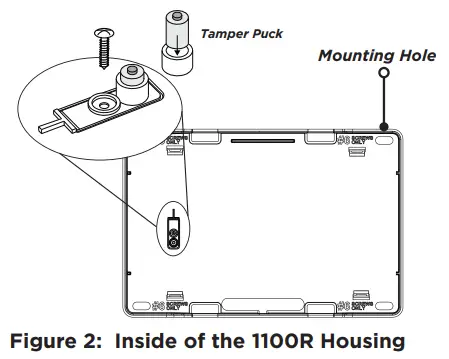
POWER THE 1100R
The 1100R can be powered from a 12 VDC external power supply such as the included DMP model 376L or an optional external DC power supply such as the DMP model 505‑12. In addition to powering the 1100R, the power supply also charges the backup battery on the 1100R that should be connected at the time of the installation. If the DC power source is removed, the power failure is indicated as an open condition on the 1100R zone.
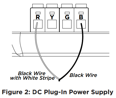
Connect a Plug-In DC Power SupplyUse the following steps to connect the model 376L plug‑in DC power supply to the 1100R:
- Connect the black wire with the white stripe to the R (red) terminal on the 1100R.
- Connect the black wire to the B (black) terminal on the 1100R.
- Plug the power supply into a wall outlet not controlled by a switch.
Connect an External Power SupplyObserve positive and negative polarity on all connections. Using a 22 AWG wire, connect the DC power terminal block to the DC terminal on the 505‑12 power supply PCB. See Figure 3.![]() Note: The DC plug‑in power supply also charges the backup battery.The 376L plug‑in power supply must be located within 100 feet of the repeater using the 22 AWG wire or 250 feet using 18 AWG wire.
Note: The DC plug‑in power supply also charges the backup battery.The 376L plug‑in power supply must be located within 100 feet of the repeater using the 22 AWG wire or 250 feet using 18 AWG wire.

ADDITIONAL INFORMATIONPrimary Power Loss IndicationWhen the 1100R is used with XT Series panels, a zone trouble indication for the repeater zone occurs within three minutes of a loss of primary power.When used with the XR150/XR550 Series panel, a power loss indication is displayed at the keypad as ‑ACPWR for the repeater zone. This occurs within three minutes but a zone trouble report to the Central Station receiver is delayed for one hour.
Replace the Backup BatteryThe 1100R’s rechargeable battery provides up to 24 hours of backup battery power when AC or DC power is not available. The battery is intended for backup power only. It should not operate the 1100R on a daily basis. If the battery is low, or not plugged into the battery connector, a low battery condition is indicated for the 1100R’s zone.Use only a DMP Model 1100RBAT800/8 for the 1100R backup battery. Replace the battery every three years. Use the steps below to remove and install a new 1100RBAT800/8 backup battery:
- Remove the 1100R housing cover.
- Disconnect the battery lead connector from the 1100R BAT header and remove the PCB from the housing.
- Remove the battery from the double-sided tape.
- Secure the new battery on the 1100R housing with double-sided sticky tape.
- Place the PCB back in the housing and reconnect the battery lead connector to the 1100R BAT header.
- Replace the 1100R housing cover.
LISTED COMPLIANCE SPECIFICATIONSCommercial FireAfter all transmitters are in position, the WLS option of the panel’s Walk Test must be operated and all transmitters programmed for Fire (FI) or Supervisory (SV) must show that their check-in message was received. Refer to the panel programming guide for Trip Counter for DMP Wireless check‑in Test (WLS) which describes that both numbers of the counter must match. If not and a failed wireless zone is displayed at END, decrease that transmitters range with the receiver and perform the WLS Walk Test again.
Powering from 376L Plug-In Power SupplyWhen using the Model 376L Transformer for Commercial Fire installations, the 1100R must be mounted on a UL-listed gang box and connected by a conduit to a Commercial Fire listed transformer enclosure.Powering from External 12 VDC Power SupplyThe 1100R is powered from a 12 VDC power supply such as a DMP Model 505‑12. In addition to powering the repeater, the power supply also charges the backup battery of the repeater. If the DC power source is removed, the power failure is indicated as an open condition on the repeater zone.
PROGRAMMING GUIDES
- XT Series Programming Guide
- XTLtouch Programming Guide
- XTLplus Installation and Programming Guide
- XR Series Programming Guide
FCC INFORMATIONThis device complies with Part 15 of the FCC Rules. Operation is subject to the following two conditions:
- This device may not cause harmful interference, and
- this device must accept any interference received, including interference that may cause undesired operation.
The antenna used for this transmitter must be installed to provide a separation distance of at least 20 cm (7.874 in.) from all persons. It must not be located or operated in conjunction with any other antenna or transmitter.Changes or modifications made by the user and not expressly approved by the party responsible for compliance could void the user’s authority to operate the equipment.![]() Note: This equipment has been tested and found to comply with the limits for a Class B digital device, pursuant to part 15 of the FCC Rules. These limits are designed to provide reasonable protection against harmful interference in a residential installation. This equipment generates, uses, and can radiate radio frequency energy and, if not installed and used in accordance with the instructions, may cause harmful interference to radio communications. However, there is no guarantee that interference will not occur in a particular installation. If this equipment does cause harmful interference to radio or television reception, which can be determined by turning the equipment off and on, the user is encouraged to try to correct the interference by one or more of the following measures:
Note: This equipment has been tested and found to comply with the limits for a Class B digital device, pursuant to part 15 of the FCC Rules. These limits are designed to provide reasonable protection against harmful interference in a residential installation. This equipment generates, uses, and can radiate radio frequency energy and, if not installed and used in accordance with the instructions, may cause harmful interference to radio communications. However, there is no guarantee that interference will not occur in a particular installation. If this equipment does cause harmful interference to radio or television reception, which can be determined by turning the equipment off and on, the user is encouraged to try to correct the interference by one or more of the following measures:
- Reorient or relocate the receiving antenna.
- Increase the separation between the equipment and receiver.
- Connect the equipment into an outlet on a circuit different from that to which the receiver is connected.
- Consult the dealer or an experienced radio/TV technician for help.
INDUSTRY CANADA INFORMATIONThis device complies with Industry Canada Licence‑exempt RSS standards. Operation is subject to the following two conditions:
- This device may not cause interference, and
- this device must accept any interference, including interference that may cause undesired operation of the device.This system has been evaluated for RF Exposure per RSS‑102 and is in compliance with the limits specified by Health Canada Safety Code 6. The system must be installed at a minimum separation distance from the antenna to a general bystander of 7.87 inches (20 cm) to maintain compliance with the General Population limits.
1100R SERIESWIRELESS REPEATER
Specifications
| Primary Operating Voltage | 12 VDC, 30 mA |
| Standby Battery | 1100RBAT800/8 |
| Voltage | 3.7 VDC |
| Capacity | 800 mAh |
| Type | Lithium Polymer,rechargeable |
| Standby | 24 hours |
| Frequency Range | 905‑924 MHz |
| Dimensions | 5.5” W x 3.75” H x 1” D |
| Color | White |
| Housing Material | Flame Retardant ABS |
Accessories
| 1100RBAT800/8 | Replacement rechargeable battery (8 pack) |
| 505‑12 | 12 VDC Power Supply |
| 376L | Plug‑In DC Power Supply |
Ordering Information1100R‑W Standard Wireless Repeater1100RE‑W Encrypted Wireless Repeater
PatentsU.S. Patent No. 7, 239, 236
CertificationsCalifornia State Fire Marshal (CSFM)FCC Part 15 ID: CCKPC0114R6Industry Canada: 5251A‑PC0114R6New York City (FDNY COA #6167)Underwriters Laboratory (UL) Listed
| • ANSI/UL 365 | Police Station Connected Burglar |
| • ANSI/UL 609 | Local Burglar Alarm Units and Systems |
| • ANSI/UL 1023 | Household Burglar Alarm System Units |
| • ANSI/UL 1076 | Proprietary Burglar Alarm Units |
| • ANSI/UL 1610 | Central Station Burglar Alarm Units |
| • ANSI/UL 985 | Household Fire Warning System |
| • ANSI/UL 864 | Fire Protective Signaling Systems |
Compatible With Devices Listed for:
- ANSI/UL 634 Connections and Switches for use withBurglar Alarm Systems Accessory
- ANSI/UL 639 Intrusion Detections Units Accessory
INTRUSION • FIRE • ACCESS • NETWORKS2500 North Partnership BoulevardSpringfield, Missouri 65803‑8877800.641.4282 | DMP.com
 report this ad
Designed, engineered, andmanufactured in Springfield, MOusing U. S. and global components.LT-1824 1.01 21062© 2021
[xyz-ips snippet=”download-snippet”]