1117 WIRELESS LEDANNUNCIATORInstallation Guide
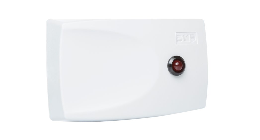
Figure 1: 1117 Wireless LED Annunciator
DESCRIPTION
The 1117 Wireless LED Annunciator provides a remote red LED for visual indication of system status. The 1117 can be programmed for nearly any panel output option and can respond to conditions such as armed area annunciation, ambush alarm, burglary alarm, exit timer, entry timer, schedules, or communication failure.
Compatibility
All DMP 1100 Series Panels Wireless Receivers v104 and higher
What is Included?
- 1117 Wireless LED Annunciator
- 3 V Lithium CR123A battery
- Hardware pack
PROGRAM THE PANEL
Program the 1117 in Output Options as an Arm-Alarm Output. Refer to the panel programming guide as needed.
- In OUTPUT INFO, enter the OUTPUT number.
- Enter the OUTPUT NAME.
- Enter the eight-digit SERIAL# and press CMD.
- Enter the SUPRVSN TIME and press CMD.
- Press the back arrow when OUTPUT SETUP displays.
- Press CMD until STOP displays and then press any select area to save and exit programming.
Program Slow ResponseUse the following output numbers to indicate whether the wireless device responds within 15 seconds to trip the output (slow response)
| Panel | Output numbers |
| XTLplus (LT-1434) | 51-54 |
| XTLtouch (LT-1789) | 51-54 |
| XR150/XR550 (LT-1232) | 450-474 |
| XT30/XT50 (LT-0981) | 31-34 |
Program Fast ResponseUse the following output numbers to indicate whether the wireless device responds within 1 second to trip the output (fast response).
| Panel | Output numbers |
| XTLplus (LT-1434) | 61-64 |
| XTLtouch (LT-1789) | 61-64 |
| XR150/XR550 (LT-1232) | 480-499 |
| XT30/XT50 (LT-0981) | 41-44 |
 Note: Supervision time is reset under the following circumstances:
- A receiver is installed, powered down, and powered up.
- The panel is reset.
- Programming is complete.
Note: If the receiver has been powered down for more than one hour, the 1117 may take up to an additional hour to send a supervision message unless tripped, tampered, or powered up. This operation extends battery life. A missing message may display on the keypad until the supervision message is sent.
POWER THE 1117
Power the 1117 with a 3 V lithium battery or a 12 VDC power supply. Do not install a battery if the 1117 is being powered by a power supply. The power supply does not charge the battery.CR123A 3 V Lithium BatteryObserve polarity when installing the included CR123A battery.
- Remove the housing cover.
- Install the supplied jumper on the two pins next to BAT on the power source header.
- Place the battery in the holder and press it into place.
- Snap the cover back into place.
12 VDC Plug-In or External Power SupplyThe 1117 can also be powered by a 12 VDC plug-in power supply (e.g. DMP Model 376L) or a 12 VDC external power supply (e.g. DMP Model 505-12). When using a plug-in power supply, mount the 1117 near a wall outlet.
- Remove the housing cover.
- Install the supplied jumper on the two pins next to EXT on the power source header.
- Wire the power supply to the DC power terminals by following the power supply-specific instructions below.
Plug-In Power SupplyConnect the black wire with the white stripe to the positive (+) terminal and the solid black wire to the negative (-) terminal. See Figure 2. Plug the power supply into a 110 VAC outlet. 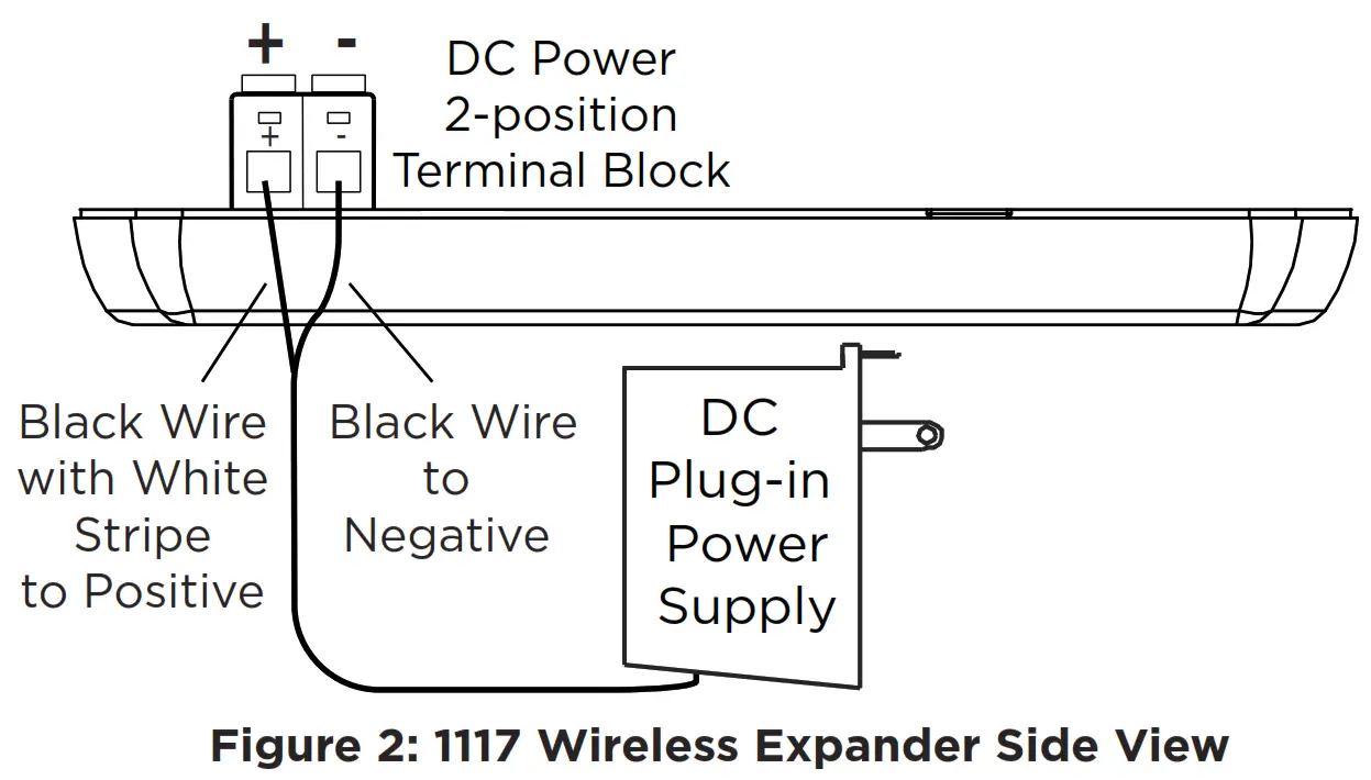
External Power SupplyUsing 22 AWG wire, connect the DC power terminal block on the 1117 to the DC power terminal on the 505-12 power supply PCB. Observe positive and negative polarity on all connections. See Figure 3.
Leave the cover off for the Survey LED.
SELECT A LOCATION
The 1117 provides a Survey LED capability to allow one person to confirm communication with the wireless receiver or panel while the cover is removed.
- With the cover removed, hold the 1117 in the exact desired location.
- Press the tamper switch to send data to the panel and determine if communication is confirmed or faulty.
 Confirmed: If communication is confirmed, for each press or release of the tamper switch, the LED blinks immediately on and immediately off. Repeat this test to confirm five separate consecutive LED blinks. Any indication otherwise means proper communication has not been established.
 Faulty: If communication is faulty, the LED remains on for about 8 seconds or flashes multiple times in quick succession. Relocate the device or receiver until the LED confirms clear communication.
MOUNT THE 1117
Mount the 1117 on a flat surface such as a wall or single-gang box. When using the optional Model 376L plug-in power supply, mount the 1117 near a wall outlet. See Figure 4 for mounting hole locations on the housing base. You will need to remove the 1117 PCB from the housing base to reach some of the mounting hole locations.
TEST THE 1117
To test the 1117 from a keypad, access the User Menu Outputs On/Off option. The device LED should light within 15 seconds of entering the assigned output number and selecting on. Refer to the User Guide as needed.
1117 LED Annunciation OperationThe 1117 LED annunciation differs based on whether it is powered by a battery or an optional power supply. When an optional power supply is connected, additional annunciations are available.The follow table shows the 1117 LED annunciation operation options.
|
Panel Programmed Action |
Power Supply Annunciation |
Battery Power Annunciation |
| STEADY | LED turns on and remains on | None |
| PULSE | LED alternates one second on, one second off | Flashes Quickly |
| MOMENTARY | LED turns on once for one second | |
| TEMPORAL (XR150/XR550 SERIES ONLY) | LED repeats the following sequence:
|
FCC INFORMATION
This device complies with Part 15 of the FCC Rules. Operation is subject to the following two conditions:
- This device may not cause harmful interference, and
- this device must accept any interference received, including interference that may cause undesired operation.The antenna used for this transmitter must be installed to provide a separation distance of at least 20 cm (7.874 in.) from all persons. It must not be located or operated in conjunction with any other antenna or transmitter.Changes or modifications made by the user and not expressly approved by the party responsible for compliance could void the user’s authority to operate the equipment.
Note: This equipment has been tested and found to comply with the limits for a Class B digital device, pursuant to part 15 of the FCC Rules. These limits are designed to provide reasonable protection against harmful interference in a residential installation. This equipment generates, uses and can radiate radio frequency energy and, if not installed and used in accordance with the instructions, may cause harmful interference to radio communications. However, there is no guarantee that interference will not occur in a particular installation. If this equipment does cause harmful interference to radio or television reception, which can be determined by turning the equipment off and on, the user is encouraged to try to correct the interference by one or more of the following measures:
- Reorient or relocate the receiving antenna.
- Increase the separation between the equipment and receiver.
- Connect the equipment into an outlet on a circuit different from that to which the receiver is connected.
- Consult the dealer or an experienced radio/TV technician for help.
Industry Canada Information
This device complies with Industry Canada License-exempt RSS standard(s). Operation is subject to the following two conditions:
- This device may not cause interference, and
- This device must accept any interference, including interference that may cause undesired operation of the device.This system has been evaluated for RF Exposure per RSS-102 and is in compliance with the limits specified by Health Canada Safety Code 6. The system must be installed at a minimum separation distance from the antenna to a general bystander of 7.87 inches (20 cm) to maintain compliance with the General Population limits.
1117 WIRELESS LED ANNUNCIATOR
Specifications
Battery
| Life Expectancy | 2 months (fast response)5 years (slow response) |
| Type | 3 V Lithium CR123A |
| Frequency Range | 905-924 MHz |
| Dimensions | 4.65” L x 3.1” W x 1.4” H |
| Color | White |
| Housing Material | Flame retardant ABS |
Accessories
| CR123 | DMP 3 V Lithium Battery |
| 376L | DC Plug-in Power Supply |
| 505-12 | 12 VDC Power Supply |
Patents
U.S. Patent No. 7,239,236
Certifications
 report this ad
FCC Part 15 Registration ID CCKPC0101IC Registration ID 5251A-PC0101
Designed, engineered, and manufactured in Springfield, MO using U.S. and global components.LT-0719 20164
INTRUSION • FIRE • ACCESS • NETWORKS2500 North Partnership Boulevard Springfield,Missouri 65803-8877800-641-4282 | DMP.com
References
[xyz-ips snippet=”download-snippet”]