![]()
1122 INTERNATIONAL WIRELESS MOTION DETECTORInstallation Guide
 DESCRIPTIONThe 1122INT Wireless PIR Motion Detector uses passive infrared technology to detect motion in a wide-angle lens pattern. The 1122INT features 128-bit AES encryption.The motion detector features a wall tamper, internal case tamper, survey LED, low battery indicator, adjustable sensitivity, and pulse count.Disarm/disable and pet immunity up to 55 lbs are available for panels with firmware Version 672 and higher.To extend battery life, the 1122INT is equipped with a 30-second sleep timer that restarts on every motion detection. This functionality allows the 1122INT to wake up after 30 seconds with no motion detected unless disarm/ disable is active.
CompatibilityAll DMP 1100INT Series Wireless Receivers (Version 700 or higher) and burglary panels Version 693 and higher. See the last page for compatibility details.What is Included?
- One 1122INT Wireless PIR Motion Detector
- One 3.0 V Lithium CR123A Battery
PROGRAM THE PANEL
When programming the 1122INT in the panel, refer to the panel programming guide as needed.
- At a keypad, enter 6653 (PROG) to access the PROGRAMMER menu. In ZONE INFORMATION, enter the zone number. Press CMD.
- Enter the zone name and press CMD.
- Select NT (Night) as the ZONE TYPE.
- Select the area.
- At the NEXT ZONE prompt, select NO.
- Select YES when WIRELESS? displays.
- Enter the eight-digit SERIAL#. Press CMD.
- Enter the SUPERVSN TIME and press CMD.
- Choose whether to enable DISARM DISABLE (panel firmware Version 672 and higher). Select YES to allow the 1122INT to be disabled for Night and Exit zones while the area is disarmed.
- Choose either 2 or 4 for the PULSE COUNT. The pulse count is the pulse inputs (trips) the 1122INT needs to sense before going into alarm.
- Choose either LOW or HIGH for the SENSITIVITY. Selecting LOW may reduce false alarms for installations in harsh environments.
- Choose whether to enable PET IMMUNITY (panel firmware Version 672 and higher).
- At the NEXT ZONE prompt, select YES if you are finished programming the zone. Select NO if you would like to access additional programming options.
- In SYSTEM OPTIONS, at the 1100 ENCRYPTION prompt, select ALL to only add encrypted wireless devices to the system. Select BOTH to allow both encrypted and non-encrypted wireless devices to be programmed.
- The default passphrase appears at entering PASSPHRASE. Press CMD to keep the default. Press any select key or area to change the passphrase and enter an 8-character hexadecimal string (0-9, A-F).
INSTALL THE BATTERY
Use only a 3.0 V lithium battery, DMP Model CR123A, or the equivalent battery from a local retail outlet. When setting up a wireless system, program zones and connect the receiver before installing batteries in the transmitters.
- Remove the holding screw at the lower end of the 1122INT case and gently lift off the cover.
- Observing polarity, place the battery in the holder and press it into place. See Figure 2 for the battery location.
SELECT A LOCATION
The 1122INT provides a survey capability to allow one person to confirm communication with the wireless receiver or panel while the cover is removed. This allows you to easily determine the best location.
Location Dos
- To locate on a rigid vibration-free surface
- Do locate so that the expected intruder’s movement will be across the detection pattern
- Do locate between 4.9 and 8.2 ft high
Location Don’ts
- Don’t locate on a surface exposed to moisture
- Don’t locate on any area containing excessive metallic surfaces
- Don’t locate within direct sunlight, heat sources (heaters, radiators, etc.), or strong air drafts (fans, air conditioner, etc.) in the field of view .
Check the Location Using Survey LED
- Hold the 1122INT in the exact desired location.
- Press the tamper switch to send data to the receiver and determine if communication is confirmed or faulty. See Figure 2 for tamper switch and LED locations.
√ Confirmed: If communication is confirmed, the survey LED turns on when data is sent to the receiver and off when an acknowledgment is received.X Faulty: If communication is faulty, the LED remains on for several seconds or flashes multiple times in quick succession. Relocate the 1122INT or receiver until the LED confirms clear communication. Proper communication between the 1122INT and receiver is verified when for each press or release of the tamper switch, the LED blinks immediately on and immediately off.
MOUNT THE 1122INT
Prior to permanently mounting the 1122INT, confirm that it is properly communicating with the panel.
- Loosen the screw located on the PCB and slide the PCB out of the unit.
- Place the 1122INT against the wall and screw through the appropriate mounting holes.Flat Wall: Choose from the mounting hole locations in Figure 3. Insert a screw in the tamper mounting hole.Corner: Choose from the mounting hole locations in Figure 4.Insert screws in the tamper mounting holes.
- Reinstall the PCB in the unit. Tighten the PCB screw to secure it into place.
- Place the cover back onto the 1122INT and tighten the holding screw back into place.

TEST COMMUNICATION TO THE PANEL
PIR Walk TestPerform a PIR Walk Test to confirm that the 1122INT is detecting motion in the necessary areas.
- At the keypad, enter 8144 (WALK) and select PIR. The 1122INT can take up to 3 minutes to begin the PIR Walk Test.
- The LED will illuminate steadily for 1 second when it detects motion.
- Walk test the unit to verify the PIR coverage.
- To manually end the test, reset the panel. The test will expire on its own after 30 minutes.
Wireless Walk TestPerform a Wireless Walk Test to confirm that the 1122INT is communicating clearly with the panel.
- At the keypad, enter 8144 (WALK) and select WLS.
- If the 1122INT fails to check-in at the keypad, relocate the 1122INT or the receiver.
ADDITIONAL INFORMATIONReplace the Battery
- Remove the holding screw at the lower end of the 1122INT and gently lift off the cover.
- Remove the old battery and dispose of it properly. See Figure 2 for battery location.
- Observing polarity, place the new battery in the holder and press it into place.Note: Use only 3.0 V lithium CR123 batteries.
- Place the cover back onto the 1122INT and tighten the holding screw back into place.
Sensor Reset to Clear LOBATWhen the battery needs to be replaced, a LOBAT message will display on the keypad. Once the battery is replaced, a sensor reset is required at the system keypad to clear the LOBAT message.
- On a Thinline keypad, press and hold “2” for two seconds. On a touchscreen keypad, press RESET.
- Enter your user code if required.
- The keypad displays SENSORS OFF followed by SENSORS ON.
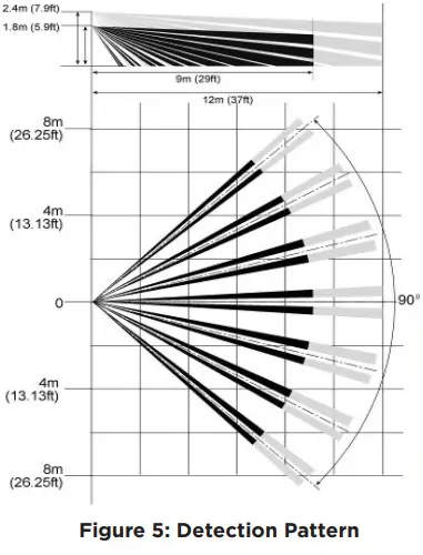
Detection PatternThe detector detects motion crossing the beam. It is more sensitive to detecting motions crossing the beams than moving toward the detector. See Figure 5.
Compatibility
- XT30INT/XT50INT, XTLplusINT/XTLtouchINT, and XR150INT/XR550INT Series panels with Version 693 and higher.
- The 1122INT is compatible with 1100INT Series Wireless Receivers with firmware Version 700 and higher.
1122 International Wireless Motion Detector
 Specifications
| Battery | |
| Life Expectancy | 3 years |
| Type | 3 V Lithium CR123A |
| Frequency Range | 863-869 MHz |
| Detection | |
| Range | 90° 40 x 40 ft |
| Speed | 1 – 5 ft/sec |
| Mounting Height | 4.9 to 8.2 ft |
| Transmit Condition | Alarm, Low Battery, Tamper |
| Dimensions | 5”L x 2.6”W x 1.5”H |
| Color | White |
| Housing Material | Flame retardant ABS |
PatentsU. S. Patent No. 7,239,236
![]() International CertificatesIntertek (ETL)
International CertificatesIntertek (ETL)
| EN 50130-4:2011 | EMC – Product Family Standard.Immunity Requirements forComponents of Fire, Intruder, andSocial Alarm Systems |
| EN 50130‑5:2011 | Alarm Systems. Environmental Test Methods |
| EN 50131‑1:2006+A1; A2 | Alarm Systems. Intrusion and Hold-upSystems. System Requirements |
| EN 50131-2-2 | Alarm Systems – Intrusion and Hold-upSystems – Passive Infrared Detectors |
| EN 50131-5-3:2017 | Alarm Systems. Intrusion systems.Requirements for InterconnectionsEquipment using Radio Frequency Techniques |
| EN 61000-3-2:2009+A1;A2 | Limits – Limits for Harmonic Current Emissions (Equipment Input Current less than or equal to 16 A per Phase) |
| EN 61000-3-3:2013 | Limits – Limitation of Voltage Changes, Voltage Fluctuations and Flicker in Public Low-Voltage Supply Systems, for Equipment With Rated Current less than or equal to 16 A perPhase and Not Subject to Conditional Connection |
| EN 61000-6-4:2018 | Generic Standard – EmissionThe standard for Industrial Environments |
 report this ad
![]()
© 2021 Digital Monitoring Products, Inc.LT-1647INT 21163INTRUSION • FIRE • ACCESS • NETWORKS2500 North Partnership BoulevardSpringfield, Missouri 65803-8877866.266.2826 | DMP.com
References
[xyz-ips snippet=”download-snippet”]