![]()
1128 WIRELESS GLASSBREAK DETECTORInstallation Guide
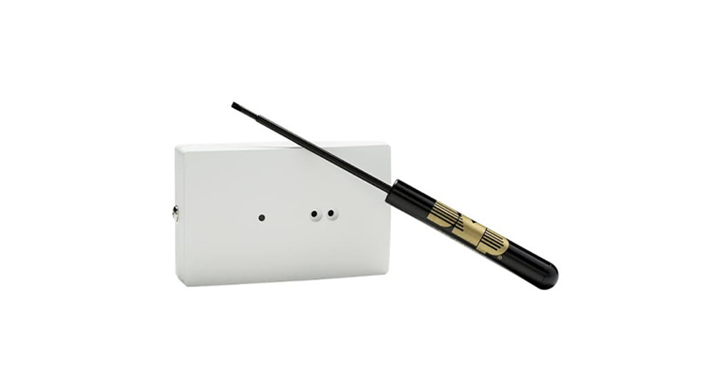
Figure 1: 1128 Wireless Glassbreak Detector
DESCRIPTION
The 1128 Wireless Glassbreak Detector is a fully supervised, low current shock and glass break sensor that provides detection coverage up to 20 ft from framed glass mounted in an outside wall. You can mount 1128 on the ceiling or on an opposing wall for maximum flexibility and coverage. 1128 operates using the supplied 3 V lithium battery.CompatibilityAll DMP 1100 Series Wireless Receivers. Glassbreak Walk Test is available on 1128 Version 2.0.0.1 and higher and with XT/XR Series Version 191 and higher. See the last page for compatibility details.
What is Included?
- One 1128 Wireless Glassbreak Detector
- One 3 V lithium CR123A battery
- Hardware Pack
PROGRAM THE PANEL
When programming 1128 in the panel, refer to the panel programming guide as needed.
- At a keypad, enter 6653 (PROG) to access the PROGRAMMER menu.
- Press CMD until ZONE INFORMATION displays and press a top row select key or area.
- Enter the wireless ZONE NO and press CMD.
- Enter the ZONE NAME and press CMD.
- Select NT (night) the ZONE TYPE.
- Select the AREA NO and press CMD.
- At the NEXT ZN? prompt, select NO and press CMD until WIRELESS? displays.
- Select YES when WIRELESS? displays and press CMD.
- Enter the eight-digit SERIAL# and press CMD.
- Enter the SUPRVSN TIME and press CMD.
- At the NEXT ZN? prompt, select YES if you are finished programming the zone. Select NO if you would like to access additional programming options.
INSTALL THE BATTERY
Keep in mind, when setting up a wireless system, program zones and connect the receiver before installing the included CR123A battery in the transmitter.
- Remove the holding screw at the lower end of the 1128 case and gently lift off the cover. See Figure 2.
- Observing polarity, place the battery in the holder and press it into place. See Figure 3 for the battery location.
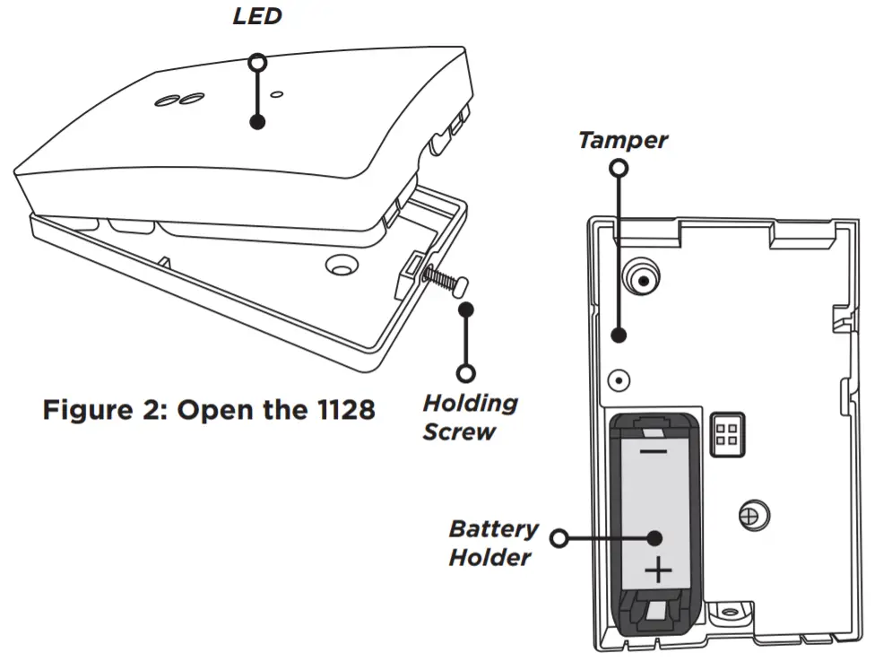
Figure 3: 1128 Battery Location
SELECT A LOCATION
The 1128’s Omni-directional detection coverage is measured from 1128 to the point on the glass farthest from 1128. Refer to the table below to determine the best location to place 1128 based on window type, glass thickness, window to wall range, and wall type.![]() Note: The sensor can be mounted as close as 3.3′ (1 m) from the glass and the minimum glass size is 1′ x 2′ (0.3 m x 0.6 m).
Note: The sensor can be mounted as close as 3.3′ (1 m) from the glass and the minimum glass size is 1′ x 2′ (0.3 m x 0.6 m).
| Window Type | Glass Thickness | Maximum Range | Wall Type |
| Plate | 3/32″ – 1/4″ (2.4mm – 6.4mm) | 20′ (6m) | Opposite, adjoining, ceiling |
| Tempered | 1/8″ – 1/4″ (3.2mm – 6.4mm) | 20′ (6m) | Opposite, adjoining, ceiling |
| Laminated | 1/8″ – 1/4″ (3.2mm – 6.4mm) | 20′ (6m) | Opposite, adjoining, ceiling |
| Wired | 1/4″ (6.4mm) | 20′ (6m) | Opposite, adjoining, ceiling |
| Armor-coated | N/A | 12′ (3.65m) | Opposite, adjoining, ceiling |
Optimize Detection
To optimize detection, install 1128 in the following areas:
- Large rooms with moderate noise
- In the direct line of sight of all windows that are to be protected
- On the opposite wall of the window that it’s protecting (see Figure 4 for detection range)
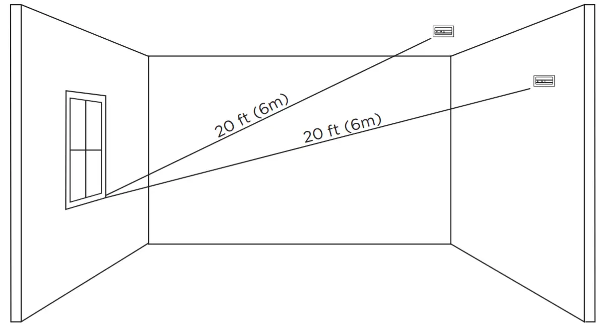
Figure 4: 1128 Detection Range
Avoid False AlarmsTo avoid false alarms, do not install 1128 in the following areas:
- Rooms with lined, insulated, or dampening drapes
- Rooms with closed, wooden shutters on the inside
- Room corners · Where white noise (air compressor) is present
- Rooms smaller than 10’x10′
- Rooms with multiple noise sources like televisions, sinks, speakers, etc.
- Excessively humid rooms
![]() Note: Avoid programming 1128 as a day or supervisory zone to help avoid false alarms.Check the Location Using the Survey LED
Note: Avoid programming 1128 as a day or supervisory zone to help avoid false alarms.Check the Location Using the Survey LED
- Hold 1128 in the exact desired location.
- Press the tamper switch to send data to the receiver and determine if communication is confirmed or faulty. See Figures 2 and 3 for tamper switch and LED locations.
 Confirmed: If communication is confirmed, the survey LED turns on when data is sent to the receiver and off when an acknowledgment is received. Repeat this test to confirm five separate consecutive LED blinks. Any indication otherwise means proper communication has not been established.Faulty: If communication is faulty, the LED remains on for several seconds or flashes multiple times in quick succession. Relocate the 1128 or receiver until the LED confirms clear communication. Proper communication between the 1128 and receiver is verified when for each press or release of the tamper switch, the LED blinks immediately on and immediately off.
MOUNT 1128
- With 1128 already open, place the 1128 base on the wall in the desired location.
- Use the provided hardware pack to mount the base to the wall. See Figure 5 for mounting hole locations.
- Reinstall the 1128 cover back onto the base and tighten the holding screw.
MOUNTING HOLES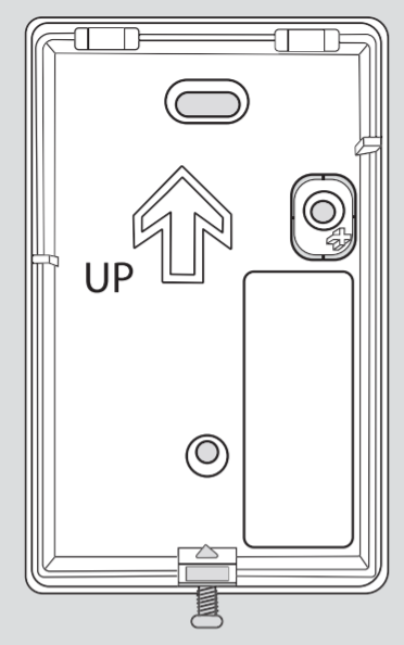 Figure 5: Mounting Holes
TEST 1128
Handheld Glassbreak TestTo test 1128, use a hand-held tester like the FG-701 to imitate glass breaking. For more information, refer to the glass break tester manual.
- Set the tester to flex mode.
- Place the FG-701 near the protected glass and press the button to activate the simulator. It will not annunciate the sound of shattering glass until a low-frequency shock is also generated.
- To generate the shock, slam a framed door to generate the appropriate low-frequency shock. The shock will also activate the FG-701 simulator.
![]() Note: 1128 has two onboard microphones. Both the high-frequency and low-frequency microphones must be activated to send an alarm to the control panel. If only the low-frequency microphone activates, the LED on 1128 will flash green. When both activate, the LED will flash red and 1128 will transmit an alarm to the control panel.Glassbreak Walk Test (v2.0.0.1 and higher)When 1128 is set into testing mode from the panel, it will trip using the tester only. There is no need to generate shock to trip the detector. XT and XR Series firmware Version 191 is required to perform the glass break walk test.
Note: 1128 has two onboard microphones. Both the high-frequency and low-frequency microphones must be activated to send an alarm to the control panel. If only the low-frequency microphone activates, the LED on 1128 will flash green. When both activate, the LED will flash red and 1128 will transmit an alarm to the control panel.Glassbreak Walk Test (v2.0.0.1 and higher)When 1128 is set into testing mode from the panel, it will trip using the tester only. There is no need to generate shock to trip the detector. XT and XR Series firmware Version 191 is required to perform the glass break walk test.
- Reset the panel.
- Type 8144 (WALK) and select PIR. All 1128s on the system will begin flashing green LED every 3 seconds to indicate that they are in testing mode. It can take up to 3 minutes for all 1128s to enter testing mode.Note: The PIR option will enable testing of all supported wireless PIRs and 1128s on the system.
- Set the tester to manual mode.
- Place the FG-701 near the protected glass and press the button to activate the simulator. If 1128 is in range, it will flash the LED red for 3 seconds to indicate it detected the crash.
- 1128 will remain in testing mode for 30 minutes or until the panel is reset.
Wireless Check-in TestPerform a Wireless Check-in Test to confirm that 1128 is communicating clearly with the panel.
- At the keypad, enter 8144 (WALK) and select WLS.
- If 1128 fails to check-in at the keypad, relocate the 1128 or the receiver.
ADDITIONAL INFORMATIONReplace the Battery
- Remove the holding screw and open the 1128 housing.
- Remove the old battery from the holder.
- Observe polarity and insert the new battery in the holder (3 V lithium CR123A battery).
- Replace the cover on the 1128 and secure the housing with the holding screw.
FCC INFORMATION
This device complies with Part 15 of the FCC Rules. Operation is subject to the following two conditions:
- This device may not cause harmful interference, and
- This device must accept any interference received, including interference that may cause undesired operation.
The antenna used for this transmitter must be installed to provide a separation distance of at least 20 cm (7.874 in.) from all persons. It must not be located or operated in conjunction with any other antenna or transmitter.Changes or modifications made by the user and not expressly approved by the party responsible for compliance could void the user’s authority to operate the equipment.![]() Note: This equipment has been tested and found to comply with the limits for a Class B digital device, pursuant to part 15 of the FCC Rules. These limits are designed to provide reasonable protection against harmful interference in a residential installation. This equipment generates, uses, and can radiate radio frequency energy and, if not installed and used in accordance with the instructions, may cause harmful interference to radio communications. However, there is no guarantee that interference will not occur in a particular installation. If this equipment does cause harmful interference to radio or television reception, which can be determined by turning the equipment off and on, the user is encouraged to try to correct the interference by one or more of the following measures:
Note: This equipment has been tested and found to comply with the limits for a Class B digital device, pursuant to part 15 of the FCC Rules. These limits are designed to provide reasonable protection against harmful interference in a residential installation. This equipment generates, uses, and can radiate radio frequency energy and, if not installed and used in accordance with the instructions, may cause harmful interference to radio communications. However, there is no guarantee that interference will not occur in a particular installation. If this equipment does cause harmful interference to radio or television reception, which can be determined by turning the equipment off and on, the user is encouraged to try to correct the interference by one or more of the following measures:
- Reorient or relocate the receiving antenna.
- Increase the separation between the equipment and receiver.
- Connect the equipment into an outlet on a circuit different from that to which the receiver is connected.
- Consult the dealer or an experienced radio/TV technician for help.
INDUSTRY CANADA INFORMATIONThis device complies with Industry Canada Licence-exempt RSS standard(s). Operation is subject to the following two conditions:
- This device may not cause interference, and
- this device must accept any interference, including interference that may cause undesired operation of the device.
This system has been evaluated for RF Exposure per RSS-102 and is in compliance with the limits specified by Health Canada Safety Code 6. The system must be installed at a minimum separation distance from the antenna to a general bystander of 7.87 inches (20 cm) to maintain compliance with the General Population limits.
1128 WIRELESS GLASSBREAK DETECTOR
Specifications
| Battery | |
| Life Expectancy | 3 Years (normal operation) |
| Type | 3 V lithium CR123A |
| Frequency Range | 905-924 MHz |
| Transmit Condition | Alarm, Low Battery, Tamper |
| Detection Method | Omni-directional |
| Range | 20 ft (6 m) |
| Operating Temperature | -10°C to +55°C |
| Color | White (passes VW1) |
| Housing Material | Flame retardant ABS |
| Dimensions | 3.3″L x 2.1″W x 0.9″D |
| Weight | 4.2 oz. |
Compatibility
- All DMP 1100 Series Wireless receivers and transmitters v106 and higherNote: If the 3rd digit of the transmitter’s serial number is greater than 0, it will be v106 or higher. If the 3rd digit is equal to zero, that transmitter must be removed or replaced with a newer transmitter for 1128 to function properly.
- All DMP Burglary Panels with built-in 1100 Series Wireless
- Test Mode requires XT/XR Series Version191 firmware
Certifications
FCC Part 15 Registration ID CCK1128IC Registration ID 5251A-1128AccessoriesFG-701 Glassbreak Simulator
![]() © 2021 Digital Monitoring Products, Inc.LT-1825 21203INTRUSION · FIRE · ACCESS · NETWORKS2500 North Partnership Boulevard Springfield,Missouri 65803-8877866.266.2826 | DMP.com
© 2021 Digital Monitoring Products, Inc.LT-1825 21203INTRUSION · FIRE · ACCESS · NETWORKS2500 North Partnership Boulevard Springfield,Missouri 65803-8877866.266.2826 | DMP.com
References
[xyz-ips snippet=”download-snippet”]