DMP 1137 Wireless LED Emergency Light
![]()
PROGRAM THE LIGHT
Refer to the panel programming guide as needed.
- Program the device as an output in Output Information during panel programming.
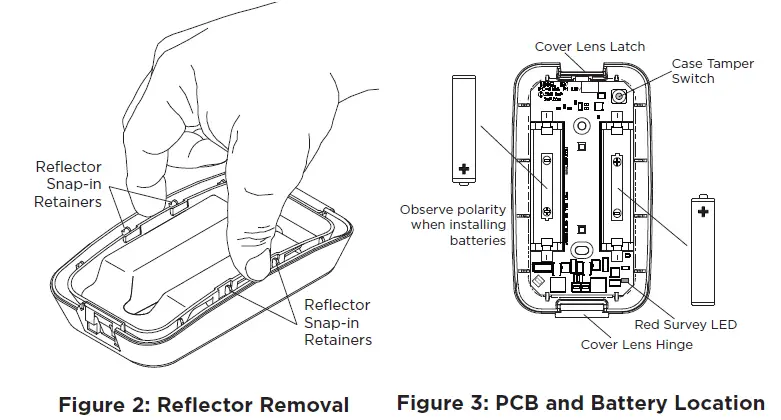
- At the Serial Number prompt, enter the eight-digit serial number. The serial number is located on the PCB between the two batteries.
- Continue to program the output as directed in the panel programming guide.In Output Information program the wireless output as:XTLplus/XTLtouch 51-54, 61-64XT30/XT50 31-34, 41-44XR150/XR550 450-474, 480-499
Trip with Panel Bell OptionSelect YES to have the 1137 lights follow the panel bell output including bell cutoff time. The ON/OFF state of the 1137 can not be changed via the output menu or any other panel function. Default is YES.
INSTALL OR REPLACE THE BATTERIES
Observe polarity when installing batteries. Use only AA Energizer Ultimate Lithium batteries.Note: When setting up a wireless system, program outputs and connect the receiver before installing batteries in the Emergency Lights.
- Open the cover lens and remove the reflector to expose the batteries (see steps 1 and 2 in Mount the Light). Remove the old batteries and dispose of properly.
- Observing polarity, place the batteries in the holders and press into place. When the batteries are installed with the proper polarity, the RED Survey LED on the PCB will immediately begin to flash. If the RED Survey LED does not begin to flash, the batteries are not installed with the proper polarity. They must be removed and installed correctly. See Figure 3.
- Snap the reflector in place and snap the cover lens in place.Caution: Properly dispose of used batteries. Do not recharge, disassemble, heat above 212°F (100°C), orincinerate. Risk of fire, explosion, and burns.

SELECT A LOCATION
The 1137 wireless LED emergency light provides a Survey LED capability to allow one person to confirm communication with the wireless receiver or panel while the cover is removed.
- With the cover removed, hold the 1137 in the exact desired location.
- Press the tamper switch to send data to the panel and determine if communication is confirmed or faulty.
Confirmed: If communication is confirmed, for each press or release of the tamper switch, the LED blinks immediately on and immediately off. Repeat this test to confirm five separate consecutive LED blinks. Any indication otherwise means proper communication has not been established.Faulty: If communication is faulty, the LED remains on for about 8 seconds or flashes multiple times in quick succession. Relocate the 1101 or receiver until the LED confirms clear communication.
MOUNT THE 1137
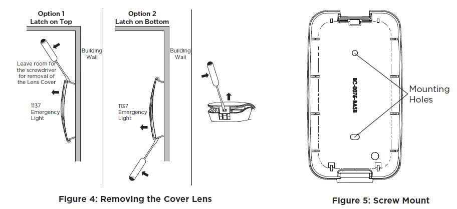
- Open the cover lens. Insert a flat screwdriver in the cover lens latch on the base and gently pry the screwdriver handle while pulling the cover lens open from the base. See Figure 4.
- The base contains the reflector, PCB and batteries. Gently squeeze and lift the reflector from the snap-in retainers on the base to expose the PCB (see Figure 2). It is not necessary to remove the PCB to access the mounting holes. See Figure 5 for mounting hole locations.
- The 1137 may be mounted with the latch toward the top or toward the bottom (see Figure 4). If mounting with the latch toward the top, it is important to leave room for access to the latch and to fully rotate the cover lens to the open position for battery installation or replacement. Using two #6 screws in the two mounting holes, mount the base vertically to the wall.
- Observing polarity, place the batteries in the holders and press into place. (See step 2 in Install or Replace the Batteries).
- Snap the reflector in place and snap the cover lens in place.
TamperThe case tamper switch is pressed when the reflector of the 1137 is secured to the base. When the reflector is removed, the 1137 sends a Tamper Trouble message to the Central Station. See Figure 3 for case tamper switch location.
ADDITIONAL INFORMATIONLow Battery IndicationWhen LO BAT is displayed on the keypad and a low battery message is sent to central station, the 1137 Emergency Light has an estimated 5 minutes of light output remaining.
FCC INFORMATION
This device complies with Part 15 of the FCC Rules. Operation is subject to the following two conditions:
- This device may not cause harmful interference, and
- this device must accept any interference received, including interference that may cause undesired operation. The antenna used for this transmitter must be installed to provide a separation distance of at least 20 cm (7.874 in.) from all persons. It must not be located or operated in conjunction with any other antenna or transmitter. Changes or modifications made by the user and not expressly approved by the party responsible for compliance could void the user’s authority to operate the equipment.Note: This equipment has been tested and found to comply with the limits for a Class B digital device, pursuant to part 15 of the FCC Rules. These limits are designed to provide reasonable protection against harmful interference in a residential installation. This equipment generates, uses and can radiate radio frequency energy and, if not installed and used in accordance with the instructions, may cause harmful interference to radio communications. However, there is no guarantee that interference will not occur in a particular installation. If this equipment does cause harmful interference to radio or television reception, which can be determined by turning the equipment off and on, the user is encouraged to try to correct the interference by one or more of the following measures:
- Reorient or relocate the receiving antenna.
- Increase the separation between the equipment and receiver.
- Connect the equipment into an outlet on a circuit different from that to which the receiver is connected.
- Consult the dealer or an experienced radio/TV technician for help.
Industry Canada InformationThis device complies with Industry Canada Licence-exempt RSS standard(s). Operation is subject to the following two conditions:
- This device may not cause interference, and
- this device must accept any interference, including interference that may cause undesired operation of the device.
This system has been evaluated for RF Exposure per RSS-102 and is in compliance with the limits specified by Health Canada Safety Code 6. The system must be installed at a minimum separation distance from the antenna to a general bystander of 7.87 inches (20 cm) to maintain compliance with the General Population limits.
Specifications
Battery
- Life Expectancy Slow response output – 2 years Fast response output – 1 year
- Type AA Energizer Ultimate Lithium Batteries
- Frequency Range 905-924 MHz
Dimensions
- Emergency Light Case 3” H x 2-1/2” W x 3/4” D
- Color White
- Housing Material Flame retardant ABS
 report this ad
PatentsU. S. Patent No. 7,239,236CertificationsFCC Part 15 Registration ID: CCKPC0155 Industry Canada: 5251A-PC0155![]()
References
[xyz-ips snippet=”download-snippet”]