![]()
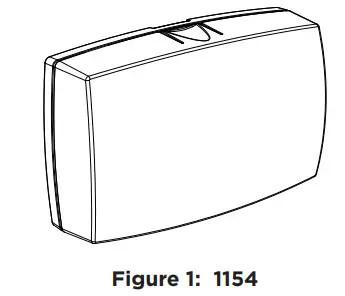
1154 WIRELESS FOUR-ZONEINPUT MODULEInstallation Guide
DESCRIPTION
The 1154 Wireless Four-Zone Input Module is designed to convert up to four existing normally closed, hardwired zones (such as motion sensors, door & window contacts, etc.) into wireless zones.When a DMP panel is installed in a location with an existing nonDMP panel, then 1154 can be connected to the existing panel’s 12 V auxiliary power. Once connected, the 154 Wireless Input Module converts up to four existing hardwired zones into wireless zones. This allows the new DMP panel to communicate with the existing zones.Compatibility
- All DMP 1100 Series Wireless Receivers and burglary panels
What is Included?
- 1154 Wireless Four-Zone Input
Module
- 3 V Lithium CR123A battery
- Hardware pack
PROGRAM THE PANEL
The 1154 can be programmed with up to four zones. When programming 1154 in the panel, refer to the panel programming guide as needed.
- In ZONE INFORMATION, enter the zone number. Press CMD.
- Enter the ZONE NAME and press CMD.
- Once ZONE TYPE appears, select the appropriate zone type. Press CMD.
- At the NEXT ZONE prompt, select NO. If you see the WIRELESS ZONE prompt, select YES.
 Note: This option only displays if the zone number can be programmed as wireless. This option does not appear for hardwire zones.
 - Enter the eight-digit SERIAL NUMBER. Press CMD.
- Enter the CONTACT number being used.
- Enter the SUPERVSN TIME and press CMD.
- At the NEXT ZONE prompt, select YES and continue to program up to three more zones. Note: Zones must be entered sequentially.
| PANEL | ZONES |
| XT30/XT50, XTLplus,& XTLtouch | The zone numbers begin with the 1154 address and are followed by the particular zone from 1154. For example. 1154 at keypad address 4 would provide zones 41. 42. 43. and 44. |
| XR150 | Zone numbers are valid from 500-599. Zones must still be programmed sequentially (i.e. 551. 552. 553. and 554). |
| XR550 | Zone numbers are valid from 500-999. Zones must still be programmed sequentially (i.e. 551. 552. 553. and 554). |
MOUNT 1154
1154 should be placed close to the existing non-DMP panel.Mount the device on a flat surface such as a wall or single-gang box. When using the optional Model 376L plug-in power supply, mount the device near a wall outlet. See Figure 2 for an example of all mounting holes on the housing base. Use any combination.
WIRE THE 1154 ZONES
Wire the zones and connect the receiver before installing the battery or connecting a power supply to 1154.
- Locate the existing Normally Closed contacts that you want to connect to 1154. These contacts should be within 100 feet of 1154.
- Use 18 to 22 gauge wire to connect a zoning device to terminals Z1+ and Z1-. 3. Repeat step 2 for the remaining zones as needed.Note: When wiring new contacts, EOL resistors do not need to be used. However, if existing contacts have EOL resistors installed, they do not need to be changed or removed. Use 18 to 22 gauge wire for all new contacts.
POWER 1154
Option A: Power from an Existing PanelUse power from an existing panel to connect 1154 to powered zones such as PIRs or glass break detectors.The existing panel must be connected to AC power. The powered zones must be connected to the existing panel or another power supply for power.
- Place the jumper on the two power source selector pins labeled EXT to enable external power supply operation.
- Using 18 to 22 gauge wire, connect a black wire to the ground terminal on the existing panel, and a red wire to a terminal on the panel with 12 VDC power. See Figure 3.
- Connect the black wire to the negative terminal on the input power terminal block on 1154, and the red wire to the positive terminal.
- Snap the housing cover into place.
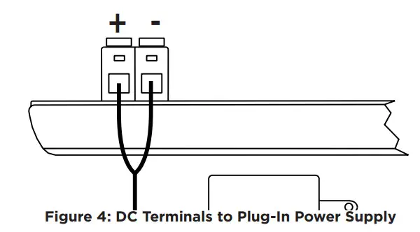
Option B: External DC Plug-In Power SupplyUse power from the optional Model 376L plug-in DC power supply to connect 1154 to powered zones. 1154 must be mounted near a wall outlet or other power source.
- Place the supplied jumper on the two power source selector pins labeled EXT to enable external power supply operation.
- Connect the wiring from the power supply to the input power terminal block. Connect the black wire to the negative terminal and the black and white wire to the positive terminal. See Figure 4.
- Plug the Model 376L power supply into a 110 VAC outlet.
- Snap the housing cover into place.
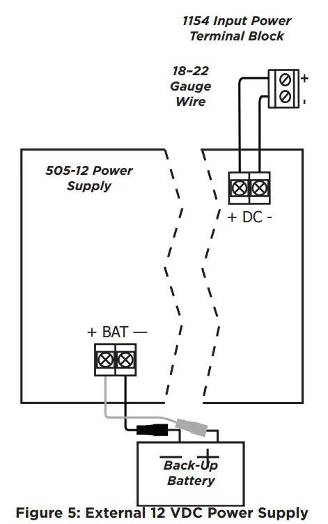
Option C: External 12 VDC Power Supply
Power the 1154 and power zones from the DMP Model 505-12 power supply or other external 12 VDC power supply with battery backup to remove the existing non-DMP panel from the setup. Use 18 to 22 gauge wire to connect 1154.
- Place the supplied jumper on the two power source selector pins labeled EXT to enable external power supply operation.
- Observing the polarity of all wired connections, use 18 to 22 gauge wire to connect the 1154’s input power terminal block to the + DC – terminal on the 505-12 power supply. See Figure 5.
- Snap the housing cover into place.
Option D: Battery PowerUse a single CR123A 3 V battery to connect 1154 to non-powered zones such as door or window contacts or battery-powered contacts.Observe polarity when installing the battery into the module.![]() Caution: Do not connect 1154 to an external power supply (existing panel, plug-in power supply, 505-12) if there is a CR-123A 3 V battery installed in the module.
Caution: Do not connect 1154 to an external power supply (existing panel, plug-in power supply, 505-12) if there is a CR-123A 3 V battery installed in the module.
- If needed, remove the old battery and properly dispose of it.
- Place the supplied jumper on the two power source selector pins labeled BAT to enable battery operation.
- Place a new battery into the holder and observe polarity.
- Snap the housing cover into place.
![]() Caution: Properly dispose of used batteries. Do not recharge, disassemble, heat above 212°F (100°C), or incinerate.
Caution: Properly dispose of used batteries. Do not recharge, disassemble, heat above 212°F (100°C), or incinerate.
FCC INFORMATION
This device complies with Part 15 of the FCC Rules. Operation is subject to the following two conditions:
- This device may not cause harmful interference, and
- This device must accept any interference received, including interference that may cause undesired operation.
The antenna used for this transmitter must be installed to provide a separation distance of at least 20 cm (7.874 in.) from all persons. It must not be located or operated in conjunction with any other antenna or transmitter.Changes or modifications made by the user and not expressly approved by the party responsible for compliance could void the user’s authority to operate the equipment.![]() Note: This equipment has been tested and found to comply with the limits for a Class B digital device, pursuant to part 15 of the FCC Rules. These limits are designed to provide reasonable protection against harmful interference in a residential installation. This equipment generates, uses, and can radiate radio frequency energy and, if not installed and used in accordance with the instructions, may cause harmful interference to radio communications. However, there is no guarantee that interference will not occur in a particular installation. If this equipment does cause harmful interference to radio or television reception, which can be determined by turning the equipment off and on, the user is encouraged to try to correct the interference by one or more of the following measures:
Note: This equipment has been tested and found to comply with the limits for a Class B digital device, pursuant to part 15 of the FCC Rules. These limits are designed to provide reasonable protection against harmful interference in a residential installation. This equipment generates, uses, and can radiate radio frequency energy and, if not installed and used in accordance with the instructions, may cause harmful interference to radio communications. However, there is no guarantee that interference will not occur in a particular installation. If this equipment does cause harmful interference to radio or television reception, which can be determined by turning the equipment off and on, the user is encouraged to try to correct the interference by one or more of the following measures:
- Reorient or relocate the receiving antenna.
- Increase the separation between the equipment and receiver.
- Connect the equipment into an outlet on a circuit different from that to which the receiver is connected.
- Consult the dealer or an experienced radio/TV technician for help.
INDUSTRY CANADA INFORMATION
This device complies with Industry Canada Licence-exempt RSS standards. Operation is subject to the following two conditions:
- This device may not cause interference, and
- This device must accept any interference, including interference that may cause undesired operation of the device.
This system has been evaluated for RF Exposure per RSS-102 and is in compliance with the limits specified by Health Canada Safety Code 6. The system must be installed at a minimum separation distance from the antenna to a general bystander of 7.87 inches (20 cm) to maintain compliance with the General Population limits.
1154 WIRELESS FOUR-ZONE INPUT MODULE
Specifications
BatteryLife Expectancy: 3 yearsType: 3 V Lithium CR123AFrequency Range: 905-924 MHzDimensions: 4.65” L x 3.10” W x 1.40” H11.81 L x 7.87 W x 3.56 H cmColor: WhiteHousing Material: Flame Retardant ABS
Accessories
CR123: DMP 3 V Lithium Battery376L: DC Plug-in Power Supply505-12: 12 VDC Power Supply
CompatibilityXT30 panels with 1100D Series Wireless Receiver with Version 105 or higherXT50 panels with the integrated wireless receiver or 1100D Series Wireless Receiver with Version 105 or higherXR150/XR550 Series panels with 1100X Series Wireless Receivers with Version 105 or higherXTLplus panels with integrated wireless receiverXTLtouch panels with integrated wireless receiver
PatentsU.S. Patent No. 7,239,236CertificationsFCC Part 15 Registration ID CCKPC0101IC Registration ID 5251A-PC0101
 report this ad
![]()
Designed, engineered, and manufactured in Springfield, MO using the U.S. and global components.LT-1619 20143© 2020INTRUSION • FIRE • ACCESS • NETWORKS2500 North Partnership BoulevardSpringfield, Missouri 65803-8877800.641.4282 | DMP.com
References
[xyz-ips snippet=”download-snippet”]