![]()
DMP 710 Bus Splitter/Repeater Module Installation Guide


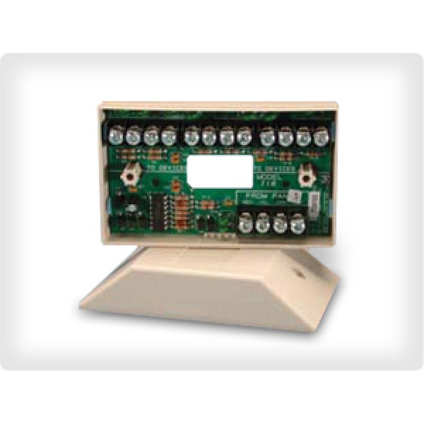
Figure 1: 710 Module
DESCRIPTION
The 710 Bus Splitter/Repeater Module expands the total number of devices and the total wire length on the LX‑Bus or Keypad Bus.
As a splitter, the module provides superior wire connection capability for up to three additional 12 VDC LX‑Bus or Keypad Bus circuits. The module’s additional circuits also makes it an excellent junction box when terminating multiple LX-Bus or Keypad Bus runs at one location.
As a repeater, the module can be installed at the end of an LX‑Bus or Keypad Bus circuit to increase the total wire length as an additional circuit.
The 710 Bus Splitter/Repeater Module is suitable for listed burglary and fire applications. For more information, refer to “Certifications”.
Compatibility
- All DMP XT and XR Series panels
- All DMP XT and XR Series International panels
- All DMP LX-Bus and Keypad Bus Devices
What is Included?
- One 710 Splitter/Repeater Module in Universal Housing
- Hardware pack
1. MOUNT THE MODULE
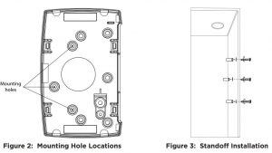
The 710 comes in a high‑impact plastic housing that you can mount directly to a wall, backboard, or other flat surface. For easy installation, the back of the housing contains multiple holes that allow you to mount the module on a single‑gang switch box or ring. The module can also be mounted in a DMP enclosure using the standard 3‑hole mounting pattern. Refer to Figure 2 and Figure 3 as needed during installation.
- Hold the plastic standoffs against the inside of the enclosure side wall.
- Insert the included Phillips head screws from the outside of the enclosure into the standoffs. Tighten the screws.
- Carefully snap the module onto the standoffs.
2. WIRE THE MODULE
Use 18 to 22 AWG wire to connect the module directly to the Keypad Bus or use a dual‑ended 4‑wire harness to connect directly to the LX‑Bus. This connection allows the module to communicate with the panel and receive 12 VDC power. Refer to Figure 4 when wiring the module.
When using an auxiliary power supply, do not connect the red wire between the panel and first device. Refer to Figure 7.
Connect to the LX‑BusAt the module, connect wires to the RED, YEL, GRN, and BLK terminals. Connect the red, yellow, green, and black wires to the corresponding 4‑wire harness leads. Connect the other end of the harness to the LX‑Bus header.
Connect to the Keypad BusAt the module, connect wires to the RED, YEL, GRN, and BLK terminals. Connect the red, yellow, green, and black wires to panel Terminal 7, 8, 9, and 10 respectively.
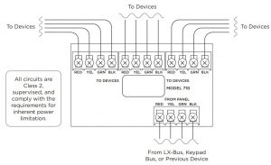
Figure 4: Module Wiring Diagram
Measure Voltage Drop
The maximum voltage drop between the panel and any device connected to the LX‑Bus or Keypad Bus is 2.0 VDC. For example, when the voltage across the red and black wires at the panel reads 13.8 VDC, the voltage measured at each device must be equal to or greater than 11.8 VDC. For more information, refer to Figure 5 and Figure 6.
If the voltage at any device, including a 710 module, is less than the required level, add an auxiliary power supply to the circuit. Increasing the wire gauge used on the circuit can reduce the voltage drop. The maximum voltage drop rule applies to LX-Bus circuits and Keypad data bus circuits powered either by the panel or by an auxiliary power supply. For more information, refer to Figure 7.
Note: To troubleshoot voltage drop, read the voltage at the last device on the LX-Bus or Keypad Bus.
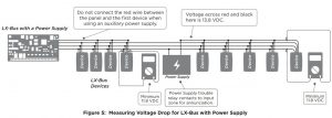
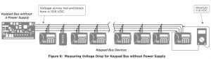
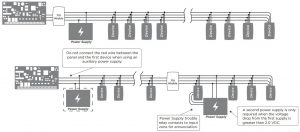
Figure 7: Installing Optional Power Supplies
Wire Multiple Circuits
In this example the first 710 module is in close proximity to the panel. At this point, the module is used to branch the LXBus or Keypad Bus into three separate circuits. Each of these circuits can be run a distance of 2,500 feet (762 meters). At the end of the 2,500 feet (762 meters), install another 710 module to add another 2,500 feet (762 meters) of LX-Bus/ Keypad Bus capability. For more information, refer to Figure 8.
Note: The total combined distance of all circuits cannot exceed 15,000 feet (4572 meters). Do not install more than 40 devices per each 2,500 ft. run.
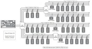
Figure 8: Wiring Multiple Circuits
ADDITIONAL INFORMATION
Use the Module as a Junction BoxTo use the 710 as a junction box, add the module to the LX-Bus or Keypad Bus circuit close to any large grouping of devices. The module enables connection to three separate wire runs to the main LX-Bus or Keypad Bus. In this application, wire nuts or other mechanical connectors are not required as all wiring terminates on the module screw terminals. For more information, refer to Figure 9.
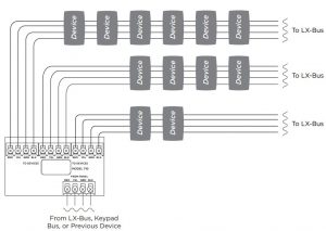
Figure 9: Using the Module as a Junction Box
710 BUS SPLITTER/ REPEATER MODULE

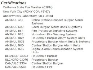
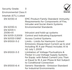
International Certifications
![]()
Designed, engineered, andmanufactured in Springfield, MOusing U.S. and global components.LT-0310 1.04 20145
© 2020
I N T R U S I O N • F I R E • A C C E S S • NETWORKS2500 North Partnership BoulevardSpringfield, Missouri 65803‑8877Domestic: 800.641.4282 | International: 417.831.9362© 2020 DMP.com
References
[xyz-ips snippet=”download-snippet”]