DMP 738I ITI – Interface Module Installation Guide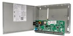
ABOUT THE 738I ITI™
The 738I ITI™ Wireless Interface Module allows you to interface ITI™ SuperBus™ 2000 Series Wireless receivers with the DMP XT30/XT50 Series and XR150/XR550 Series panels. This module allows up to 96 supervised, programmable zones of ITI wireless transmitters when used with the ITI™ MAX SuperBus™ 2000 Radio Receiver. The 738I allows 32 zones when used with the ITI™ 32-Zone SuperBus™ 2000 Radio Receiver and allows 16 zones when used with the ITI™ 16-Zone SuperBus™ 2000 Radio Receiver. Tables 1 and 2 list compatible wireless receivers and transmitters.
Supported Wireless Receivers and Transmitters
The maximum wire distance between the ITI wireless receiver and the 738I is 3 feet. Table 1 lists the wireless receivers supported and Table 2 lists the wireless transmitters supported
| MODEL NAME | NUMBER OF SUPPORTED ZONES | ||
| XT30 | XT50 | XR150/XR550 | |
| 16-Zone SuperBus™ 2000 Radio Receiver | 16 | 16 | 16 |
| 32-Zone SuperBus™ 2000 Radio Receiver | 16 | 32 | 32 |
| MAX SuperBus™ 2000 Radio Receiver | 16 | 32 | 96 |
Table 1: ITI Wireless Receivers Supported
| MODEL NAME | ITI MODEL NAME |
| 2-Button SAW Keychain Touchpad | 60-707-0195R |
| 4-Button SAW Keychain Touchpad* | 60-659-95R |
| 2-Button Crystal Keyfob | 60-607-319.5 |
| 4-Button Crystal Keyfob* | 60-606-319.5 |
| SAW Door/Window Sensor | 60-670-95R |
| Crystal Standard Door/ Window Sensor | 60-362-10-319.5 |
| Crystal Long-Life Door/ Window Sensor | 60-641-95 |
| Recessed Micro Door/ Window Sensor | 60-741-95 |
| Crystal PIR Motion Sensor | 60-703-95 |
| MODEL NAME | ITI MODEL NUMBER |
| SAW PIR Motion Sensor | 60-639-95R |
| Wireless AP750W PIR Motion Sensor | 60-880-95 |
| SAW Pet Immune PIR Motion Sensor | 60-807-95R |
| DS 924i Pet Immune PIR Motion Sensor | 60-511-02-95 |
| SAW Outdoor PIR Motion Sensor | 60-639-95R-OD |
| Water-Resistant Pendant Panic Sensor | 60-578-10-95 |
| Wrist Watch Panic Sensor | 60-906-95 |
| Wireless ShatterPro™ Glassbreak Sensor | 60-873-95 |
| Learn Mode DS 924i PIR Motion Sensor | 60-511-01-95 |
Table 2: ITI Wireless Transmitters Supported
Note: During 738I programming, the keyfob can be assigned to one zone that operates only the top two buttons by selecting Arming zone, style Maintain. After programming is complete, the Lock button enables a maintained Short condition that arms the assigned area(s). The Unlock button restores the zone to a Normal condition that disarms the assigned area(s).
INSTALL THE 738I ITI™
Mount the Module
Mount on Wall
The module comes in a case that mounts directly to walls, backboards, or other flat surfaces. Wire entrances are on the back and each side of the case. Two screw holes at the bottom of the case are for mounting the case on single-gang switch boxes or rings.
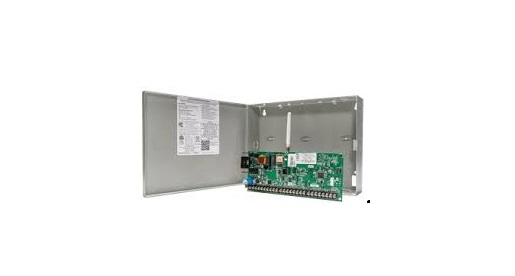
Mount in Enclosure
The module can be mounted in a DMP enclosure using the standard 3-hole mounting pattern. Refer to Figure 1 as needed during installation.
- Hold the plastic standoffs against the inside of the enclosure side wall.
- Insert the included Phillips head screws from the outside of the enclosure into the standoffs. Tighten the screws.
- . Carefully snap the module onto the standoffs.

Wire the Module
The 738I connects to the panel 4-wire keypad data bus of XT30/XT50 Series panels and panel 4-wire keypad data bus and the LX-Bus™ of XR150/XR550 Series panels. Use a 4-wire harness to easily connect the 738I to an ITI Wireless Receiver.
Note: When programming 738I zones on the LX-Bus of an XR150/XR550 Series panel, select NO when prompted whether the zone is wireless
DMP Bus Header
For connection to a keypad bus, connect the provided Model 300 4-wire harness (with one 4-wire connector) from the DMP BUS header to the panel terminals marked Red (7), Yellow (8), Green (9), and Black (10).For connection to the LX-Bus, connect the provided Model 300 4-wire harness from the DMP BUS header to the four wires of the LX-Bus.
Receiver Header
Connect the provided Model 300 4-wire harness from the RECEIVER header to the ITI wireless receiver.
- Red = +12
- Green = B
- Yellow = A
- Black = GND
PROG Header
When programming the 738I, connect the provided Model 330 programming cable (with two 4-wire connectors) from the PROG header to any DMP thin line, wireless, or graphic touchscreen keypad.
PROGRAM Header
- Place the provided jumper across the PROGRAM header to enter 738I programming mode.
- After programming, remove the jumper from the header and place it over one pin for future use.
Figure 2: 738I Connection
- A. DMP Bus Header: Use Model 300 4-Wire Harness to DMP Keypad Bus or LX-Bus
- B. Receiver Header: Use Model 300 4-Wire Harness to ITI Receiver
- C. PROG Header: Use Model 330 Programming Harness to DMP Keypad for programming.
- D. PROGRAM Header
PROGRAM THE 738I ITI™
- Connect the Model 330 Programming Cable from the PROG header to any DMP thinline, wireless, or graphic touchscreen keypad set to address 1. Refer to the specific keypad installation sheet for information on changing the keypad address.
- Place the jumper across the PROGRAM header. The 738I immediately enters programming mode.
- Press the CMD key to continue.Note: While in programming mode, all 738I communication to the panel stops.
Initialization
Press the Select key under YES to reset all programming options to the factory default. Press the Select key under NO to maintain all programming options at their current settings.
Panel Bus Type
Press the Select key under KYPD when connecting the 738I to the panel keypad bus. Press the Select key under LX when connecting the 738I to the panel LX-Bus. Press the CMD key to accept the selection. An asterisk appears to the left of the bus type selected.
Zone Number
Enter the two-character zone number (01 – 96) to be programmed. If the zone number is less than 10, enter a leading zero, such as 01. Refer to Table 3 for Keypad Bus Zone numbers. Press CMD to accept the entry.
For LX-Bus Zone Numbers, enter the right two digits of the zone number. The panel automatically enters the hundreds digit representing the LX-Bus slot where the card is installed. See Tables 4 and 5. Press CMD to accept the entry.
| KEYPAD ADDRESS | ZONE NUMBERS | |
| XT30/XT50 | XR150/XR550 | |
| 1 | 11 to 14 | 11 to 14 |
| 2 | 21 to 24 | 21 to 24 |
| 3 | 31 to 34 | 31 to 34 |
| 4 | 41 to 44 | 41 to 44 |
| 5 | N/A | 51 to 54 |
| 6 | N/A | 61 to 64 |
| 7 | N/A | 71 to 74 |
| 8 | N/A | 81 to 84 |
| Note: XR550 Series panels support 16 addresses. 738I only supports 8 addresses. |
Table 3: ITI Wireless Receivers Supported
| LX-BUS ZONE NUMBERS | ||||||
|
738I ZONE |
XR150 SERIES | XR550 SERIES | ||||
| LX-BUS
500 |
LX-BUS
500 |
LX-BUS
600 |
LX-BUS
700 |
LX-BUS
800 |
LX-BUS
900 |
|
| 1 | 501 | 501 | 601 | 701 | 801 | 901 |
| 2 | 502 | 502 | 602 | 702 | 802 | 902 |
| 3 | 503 | 503 | 603 | 703 | 803 | 903 |
| 4 | 504 | 504 | 604 | 704 | 804 | 904 |
| … | ||||||
| 16 | 516 | 516 | 616 | 716 | 816 | 916 |
| 17 | 517 | 517 | 617 | 717 | 817 | 917 |
| … | ||||||
| 32 | 532 | 532 | 632 | 732 | 832 | 932 |
| 33 | 533 | 533 | 633 | 733 | 833 | 933 |
| … | ||||||
| 44 | 544 | 544 | 644 | 744 | 844 | 944 |
| 45 | 545 | 545 | 645 | 745 | 845 | 945 |
| … |
Table 4: LX-Bus Zone Numbers
| LX-BUS ZONE NUMBERS | ||||||
|
738I ZONE |
XR150 SERIES | XR550 SERIES | ||||
| LX-BUS
500 |
LX-BUS
500 |
LX-BUS
600 |
LX-BUS
700 |
LX-BUS
800 |
LX-BUS
900 |
|
| 57 | 557 | 557 | 657 | 757 | 857 | 957 |
| 58 | 558 | 558 | 658 | 758 | 858 | 958 |
| … | ||||||
| 66 | 566 | 566 | 666 | 766 | 866 | 966 |
| 67 | 567 | 567 | 667 | 767 | 867 | 967 |
| … | ||||||
| 78 | 578 | 578 | 678 | 778 | 878 | 978 |
| 79 | 579 | 579 | 679 | 779 | 879 | 979 |
| … | ||||||
| 81 | 581 | 581 | 681 | 781 | 881 | 981 |
| 82 | 582 | 582 | 682 | 782 | 882 | 982 |
| … | ||||||
| 95 | 595 | 595 | 695 | 795 | 895 | 995 |
| 96 | 596 | 596 | 696 | 796 | 896 | 996 |
Table 5: LX-Bus Zone Numbers Continued
Transmitter Type
Enter a transmitter type by pressing the Select keys below the type of transmitter used as shown on the LCD. For example, press the third from the left Select key to choose unsupervised. Refer to the installation instructions provided with the ITI transmitter for additional information. Default is UN. An asterisk appears to the left of the transmitter type chosen. Press the CMD key to accept selection.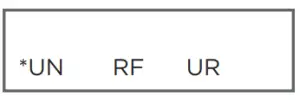
- UN = Unused Zone
- RF = Supervised Transmitter
- UR = Unsupervised Transmitter
When a wireless transmitter reed switch, contact, or button is in a faulted condition, then the corresponding panel zone is shorted. When a wireless transmitter tamper is in a faulted condition, the corresponding panel zone is open. A supervised transmitter must report to the 738I at least once every 30 hours or that zone is indicated as missing to the DMP panel.
Transmit Now
This is the transmitter learn function and the message displays until the learn function completes. You must trip the transmitter tamper by removing the cover. This sends a transmitter identification to the 738I, identifying the device. The 738I stores the identification and learns the transmitter.
Already Zone
Indicates that the transmitter has previously been learned as a zone. This message continuously displays until the Back Arrow or CMD key is pressed. When the Back Arrow key is pressed, programming returns to TRANSMIT NOW to allow a different transmitter to be learned. When the CMD key is pressed, programming returns to ZONE number. (xx = zone number)
External Contact
Select the type of external contact the transmitter is using.Press the Select key under NC for a Normally Closed circuit.Press the Select key under NO for a Normally Open circuit.Press the Select key under UN if an external contact is not used on this transmitter. An asterisk appears next to the currently selected option.Exit Programming
Remove the jumper from the PROGRAM header to exit the 738I programming mode. Place the jumper over one pin for future use. Remove the Model 330 cable and the 32 character keypad from PROG header. After exiting programming mode, all zone states report to the panel as NORMAL. Test and verify all zones for proper communication.
738I LED Operation
The green LED on the 738I Module indicates data transmission to the panel.
- On: There are no transmitters programmed.
- Off: The 738I is not being programmed, or the 738I is not responding to the panel.
- Flashes: The 738I is transmitting data to the panel, or it is being programmed.
COMPATIBILITY
- XT30/XT50 Series Panels
- XR150/XR550 Series Panels
PRODUCT SPECIFICATIONS
- Primary Power : 12 VDC
- Current Draw : 42 mA
- Zones : 5 VDC, 2 mA max
- Dimensions : 4.5” W x 2.75” H x 1.75” D 11.43 W x 7 H x 4.45 D cm
CERTIFICATIONS
FCC Part 15
 report this ad
Information furnished is believed to be accurate and reliable. This information is subject to change without notice.
[xyz-ips snippet=”download-snippet”]