DOIT Installation for TS100 Installation Guide

Introduction
This user manual is used for the installation of TS100 generated by SZdoit, together with the motor connection with the development board. Specially, the installation is very similar to the other T series tank chassis from SZdoit, excluding the shock suspension. Therefore, the installation is very convenient.
Installation for Driving wheel (two wheels for one TS100)
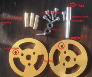
a) Material for one driving wheel:
-
-
- Aluminum alloy coupling: 1pcs (with 3 types for the different motors: Φ4、Φ5、Φ6mm, the default size is Φ4mm)
- 17mm copper pillar: 3pcs
- M3*8 screw: 6pcs
- M4*10: 1pcs
- Jackscrew: 2pcs
-
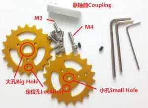
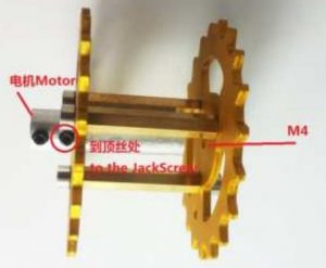
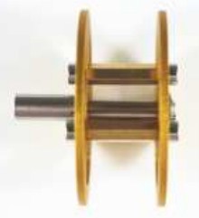
b) Firstly, put jackscrew to aluminum alloy coupling, and let copper pillar to wheel pieces
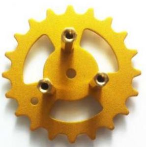
c) After install the two wheel pieces together, and then let the coupling pu through the wheel piece with big hole firstly.
Note:
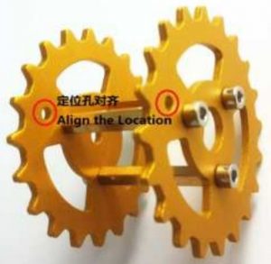
- Let the location hole align with each other;
- The wheel piece with small hole is connected to M4 screw, and the other is connected to motor.
Reminder: all the accessories, e.g. can be purchased in our official site www.smartarduino.com
Installation for bearing wheel (one TS100 needs10pcs bearing wheel)
a) Material for one bearing wheel:
-
- 17mm copper pillar: 3pcs
- M3*8 screw: 6pcs
- stainless steel connector: 1pcs
- M2 screw: 1pcs
- cup bearing: 2pcs
- wheel piece: 2pcs (note: when install the wheel, please let the location hole is aligned with each other)
d) Install the copper pillar to the 2pcs wheel piecesFirstly, install 3pcs copper pillar to one wheel piece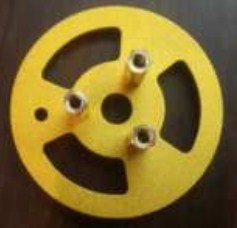
e) Then, let another pcs wheel piece to install the pillar to it. Note that, please let the location isaligned with each other.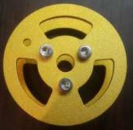
f) Let one cup bearing through the stainless steel
g) Then install one wheel piece to install the stainless steel with cup bearing, and later install another wheel piece. Use a M2 screw to fix the outside wheel piece.
 Some notation when install the bearing wheel
- Align the wheel pieces;
- After installation the bearing wheel. Let the bearing wheel turn to test whether it is smooth. If not, then loose the M2 screw.
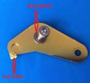
Install the shock suspension (the total is 8pcs,including left and right 4pcs)
a) Materials when install a shock suspension:
-
- Installed bearing wheel: 1pcs
- Shock suspension bracket: 1pcs
- Cup bearing: 1pcs
- M4*8 screw: 2pcs
- M4 screw nut: 1pcs
- Spring: 1pcs


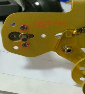
b) firstly, put the cup bearing into the centre hole of the shock suspension bracket. Importantly, thehook must on the top surface.
c) Use M4*8 screw to connect the bearing wheel and the shock suspension bracket.
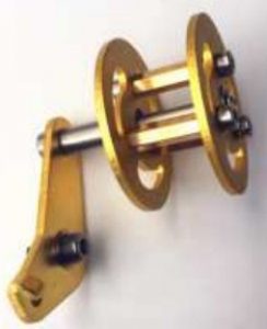
d) Then, use M4*8 screw and nut to fix on the side plate, shown in the following picture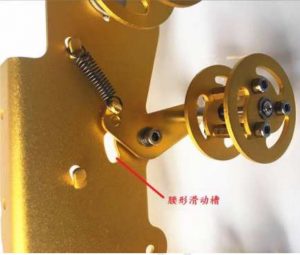
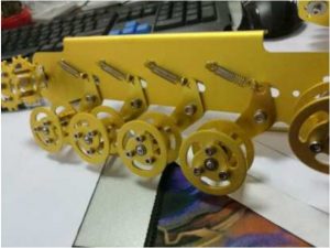 Importantly, you must the direction of the bearing wheels are the same, shown in the follong picture
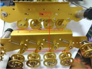
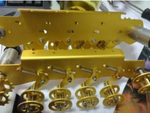
Installation a bearing wheel to the side plate(left and right)
The wheel can adjust the length of track
a) Material when install a bearing wheel
-
- bearing wheel: 1pcs
- 16mm gasket: 2pcs
- M4 screw: 1pcs
- leave enough space to adjust the track when install this bearing wheel to the side plate

Summary
a) Materials
-
-
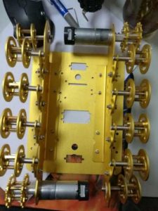
- Metal panel: 1pcs
- Left and right installed side plate with bearing wheel
- Installed driving wheel: 2pcs
- Motor: 2pcs
- Track: 2pcs
- M3*12 screw: 8pcs
- M3 nut: 8pcs
- M3*10 screw: 4pcs
-
b) Install the motor with m3*10 screw
c) Install the driving wheel and connect the motor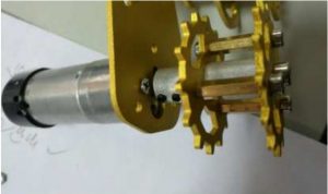
d) Install the metal panel
e) Adjust the length of the track and install it to the car chassis. Note, the track can be changed atrandom length.
f) Install the track to the wheel. Note, the length can be changed randomly.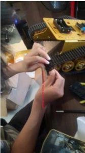
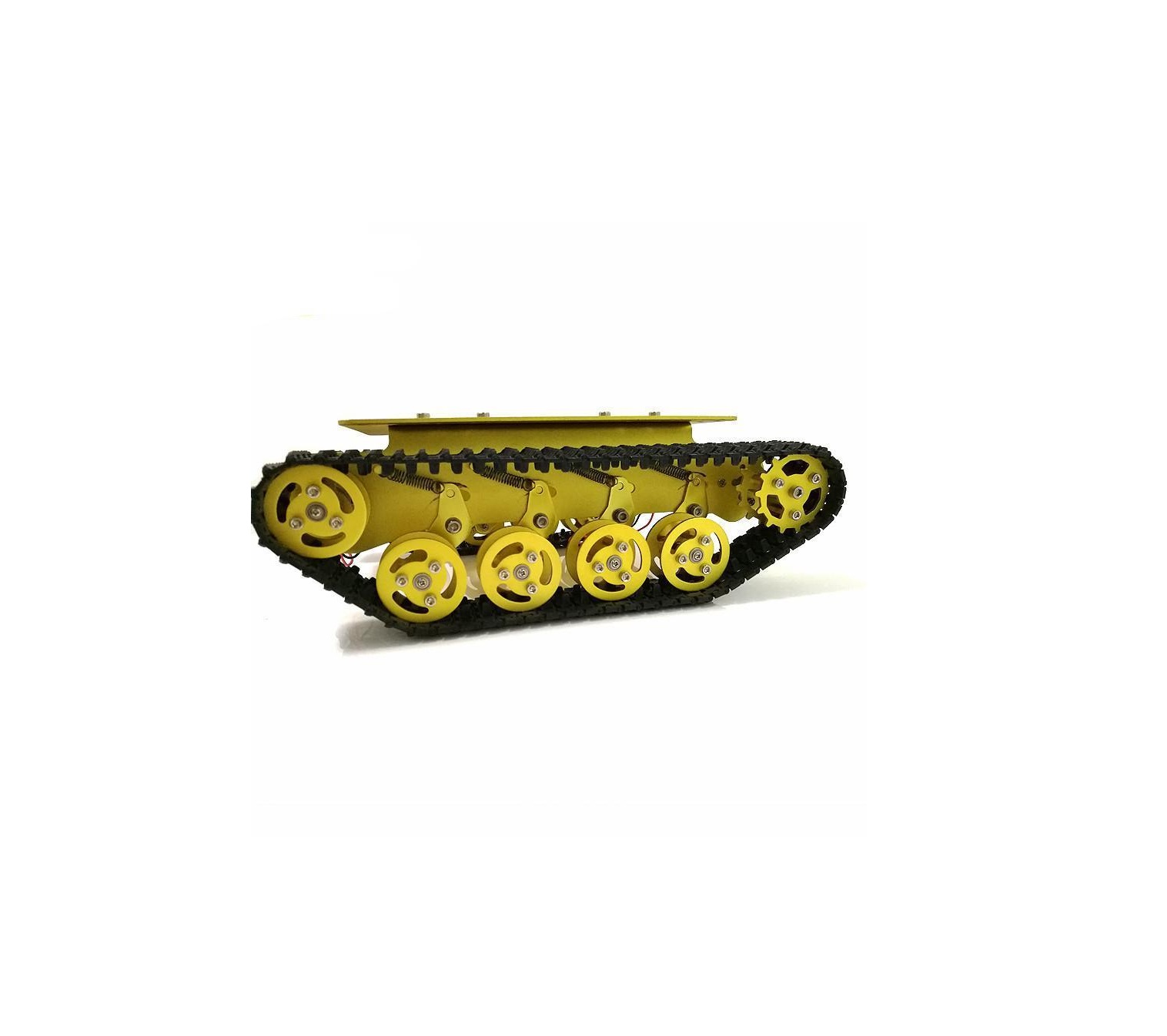
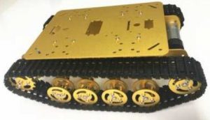
g) The complete TS100 after installation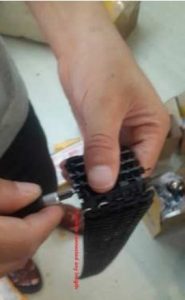
 Some Notations
-
- Align the location hole when install the wheels;
- Track can be changed randomly;
- Note the screw models when install the car;
- m2 don’t fix to tight when install the bearing wheel;
- By adjust the location of the end of bearing wheel, can adjust the track;
- The same direction is necessary when install the shock suspension; more details, please visit doit official site. www.doit.com.
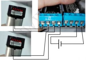
Connection for the motor
When you get this chassis, you can find the related product in our site www.smartarduino.com , This motor has Hall sensor, which can be used to measure the speed. If we face the shaft of the motor,the interface is VM (power for motor),GM( GND for motor);V(power for Hall sensor),G (GND for Hall sensor);S1(signal from the first sensor),S2(signal from the 2nd sensor)
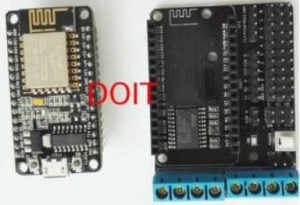
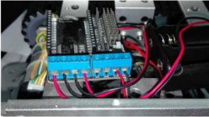
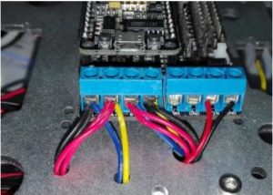
If you use our controller kit, you can get it from the smartarduino.com, and the connection is shownin the following

Support and service
- Any problem, please contact us by the following.Emails: [email protected]; [email protected]Skype: yichoneWhatsapp: 008618676662425
References
robotics | smart arduino car | robot tank car chassis | wifi module |esp8266| esp8285| [email protected] Official
SZDOIT – By Yichone – Facebook Messager
淘宝网 – 淘!我喜欢
robotics | smart arduino car | robot tank car chassis | wifi module |esp8266| esp8285| [email protected] Official
robotics | smart arduino car | robot tank car chassis | wifi module |esp8266| esp8285| [email protected] Official
[xyz-ips snippet=”download-snippet”]