![]()
DRIVING SUPPORTPERFECTVIEW
CAM 35
© 2021 Dometic Group. The visual appearance of the contents of this manual is protected by copyright and design law. The underlying technical design and the products contained herein may be protected by design, patent or be patent pending. The trademarks mentioned in this manual belong to Dometic Sweden AB. All rights are reserved.
Explanation of symbols
Please read these instructions carefully and follow all instructions, guidelines, and warnings included in this product manual in order to ensure that you install, use, and maintain the product properly at all times. These instructions MUST stay with this product.By using the product, you hereby confirm that you have read all instructions, guidelines, and warnings carefully and that you understand and agree to abide by the terms and conditions as set forth herein. You agree to use this product only for the intended purpose and application and in accordance with the instructions, guidelines, and warnings as set forth in this product manual as well as in accordance with all applicable laws and regulations. A failure to read and follow the instructions and warnings set forth herein may result in an injury to yourself and others, damage to your product or damage to other property in the vicinity. This product manual, including the instructions, guidelines, and warnings, and related documentation, may be subject to changes and updates. For up-to-date product information, please visit dometic.com.
Explanation of symbols
![]() WARNING! Safety instruction: Indicates a hazardous situation that, if not avoided, could result in death or serious injury.
WARNING! Safety instruction: Indicates a hazardous situation that, if not avoided, could result in death or serious injury.
![]() NOTICE!Indicates a situation that, if not avoided, can result in property damage.
NOTICE!Indicates a situation that, if not avoided, can result in property damage.![]() NOTESupplementary information for operating the product.
NOTESupplementary information for operating the product.
Safety and installation instructions
![]() WARNING!Danger of personal injury by vehicle.Reversing video systems are designed merely as an additional aid for reversing, however, this does not relieve you of the duty to take proper care when reversing.Please observe the prescribed safety instructions and stipulations from the vehicle manufacturer and service workshops.
WARNING!Danger of personal injury by vehicle.Reversing video systems are designed merely as an additional aid for reversing, however, this does not relieve you of the duty to take proper care when reversing.Please observe the prescribed safety instructions and stipulations from the vehicle manufacturer and service workshops.
Please note the following:
- To prevent the risk of short circuits, always disconnect the negative terminal of the vehicle’s electrical system before working on it. If the vehicle has an additional battery, its negative terminal should also be disconnected.
- Inadequate supply cable connections could result in short circuits, causing:
- Cable fires
- The airbag being triggered
- Damage to electronic control equipment
- Electrical malfunctions (indicators, brake light, horn, ignition, lights)
- When working on the following cables, only use insulated cable terminals, plugs and flat sockets:
- 30 (direct supply from positive battery terminal)
- 15 (connected positive terminal, behind the battery)
- 31 (return cable from the battery, earth) 58 (reversing light)Do not use porcelain wire connectors.
- Use a crimping tool to connect the cables.
- Screw the cable when connecting cable 31 (earth)
- Screw on the cable using a cable terminal and serrated washer to one of the vehicle’s earth bolts or Screw the cable to the bodywork using a cable terminal and a self-tapping screwMake sure there is a good earth connection.
If you disconnect the negative terminal of the battery, all data stored in the volatile memories will be lost.
- The following data must be reset, depending on the vehicle equipment options:
- Radio code
- Vehicle clock
- Timer
- On-board computer
- Seat positionYou can find instructions for making these settings in the operating manual.
Observe the following installation instructions:
- Secure the parts of the camera which are installed in the vehicle in such a way that they cannot become loose under any circumstances (sudden braking, accidents) and cause injuries to the occupants of the vehicle.
- Secure any parts of the system concealed by the bodywork in such a manner that they cannot be come loose or damage other parts or cables, or impair vehicle functions (steering, pedals, etc).
- To prevent damage when drilling, make sure there is sufficient space on the other side for the drill head to emerge.
- Deburr all drill holes and treat them with a rust-protection agent.
- Always follow the safety instructions of the vehicle manufacturer. Some work (e.g. on retention systems such as the AIRBAG etc.) may only be performed by qualified specialists.
Observe the following instructions when working with electrical parts:
- When testing the voltage in electrical cables, only use a diode test lamp or a voltmeter.Test lamps with a bulb consume too much voltage, which can damage the vehicle’s electronic system.
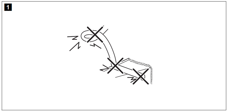
- When making electrical connections, ensure that:
- they are not kinked or twisted
- they do not rub on edges
- they are not laid in sharp-edged ducts without protection (fig.
1, page 3).
- Insulate all connections.
- Secure the cables against mechanical wear by using cable binders or insulating tape, for example on existing cables.
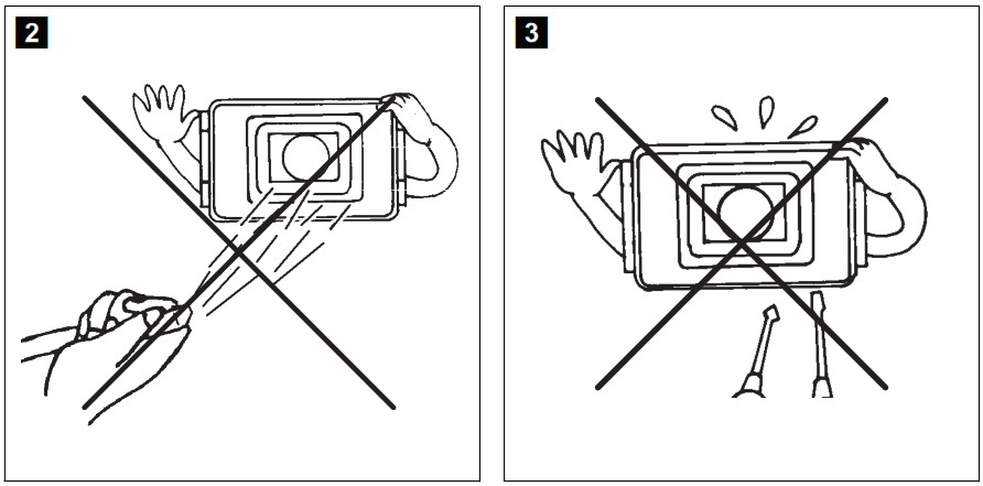
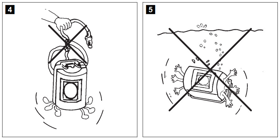
The camera is watertight. However, the seals on the camera cannot withstand a highpressure cleaner (fig. 2, page 3). Therefore, you should observe the following instructions when handling the camera:
- People (including children) whose physical, sensory or mental capacities or whose lack of experience or knowledge prevent them from using this product safely should not use it without the supervision or instruction of a responsible person.
- Do not open the camera, as this impairs the leak tightness and the function of the camera (fig.
3, page 3). - Do not pull at the cables, as this impairs the tightness and the function of the camera (fig.
4, page 3). - The camera is not suitable for use under water (fig.
5, page 3)!
Scope of delivery
|
No. infig. 6, page 4 |
Quantity | Description |
Ref. no. |
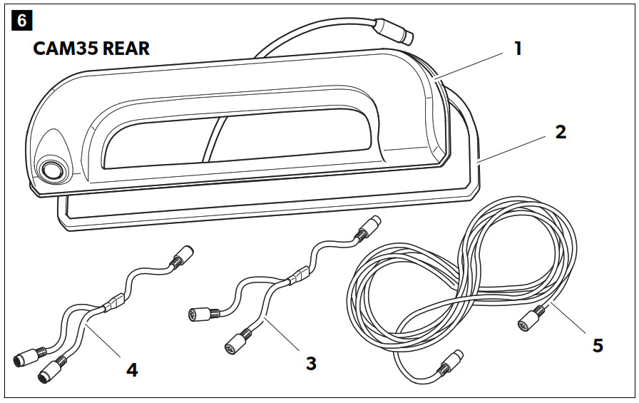
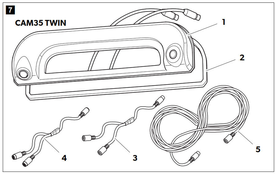
| 1 | 1 | Camera CAM35CAM35 REARCAM35 REAR NAVCAM35 TWINCAM35 TWIN NAV | 9102000134910200013391020001329102000131 |
| 2 | 1 | Seal | – |
| 3 | 1 | CAM35 Y adapter CAM | 9600000552 |
| 4 | 1 | CAM35 Y adapter MON | 9600000553 |
| 5 | 1 | System cable | 9600000137 |
| – | 1 | NAV adapter (only CAM35 REAR NAV or CAM35 TWIN NAV) | 9600000554 |
| – | 2 | Fastening bolts 6 x 25 mm | |
| – | – | Installation and operating manual |
Intended use
The double camera CAM35 is primarily intended for use in the vehicles Fiat Ducato, Citroën Jumper, Peugeot Boxer starting from model year 2006 with single roof. The camera console is mounted between the bodywork and the brake light. It can be used in video systems to observe the space around the vehicle from the driver’s seat when maneuvering or parking, for example.This product is only suitable for the intended purpose and application in accordance with these instructions.This manual provides information that is necessary for proper installation and/or operation of the product. Poor installation and/or improper operating or maintenance will result in unsatisfactory performance and a possible failure.The manufacturer accepts no liability for any injury or damage to the product resulting from:
- Incorrect assembly or connection, including excess voltage
- Incorrect maintenance or use of spare parts other than original spare parts provided by the manufacturer
- Alterations to the product without express permission from the manufacturer
- Use for purposes other than those described in this manual
Dometic reserves the right to change product appearance and product specifications.
Technical description
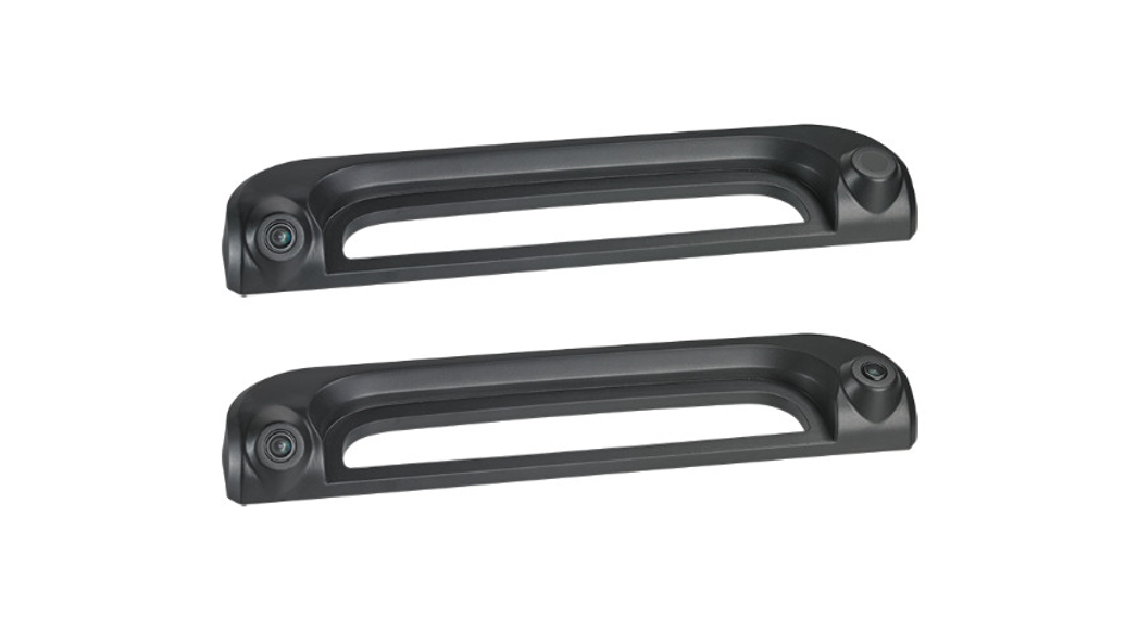
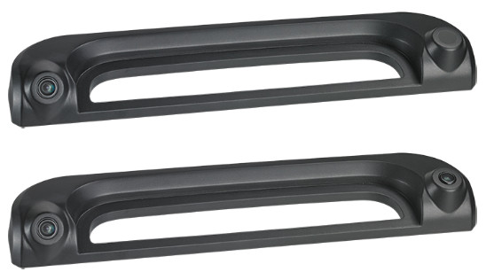
The reversing camera and the long-distance camera (only CAM35 TWIN) are housed in one console for the original brake light. The camera image is transferred to a monitor via a system cable. The CAM35 is also suitable for connection to the original Fiat navigation system Uconect, as the cameras provide an NTSC video signal.The camera consists of the following elements:
|
No. infig. 6, page 4 |
Description |
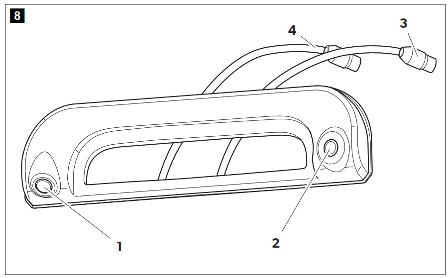
| 1 | Reversing camera |
| 2 | Long-distance camera (only CAM35 TWIN) |
| 3 | 6-pin connection cable for long-distance camera (only CAM35 TWIN) |
| 4 | 6-pin connection cable for reversing camera |
Only for CAM35 TWINIn the CAM35 TWIN, a monitor with two video inputs must be connected that can be switched between the image of the reversing and the long-distance cameras.The long-distance camera transmits the image as if you were looking in the rear view mirror.
Only for CAM35 NAVThe cameras CAM35REAR NAV and CAM35 TWIN NAV can be connected to monitors from other manufacturers. A universal adapter is included (CAM35 NAV adapter).
Fitting the camera
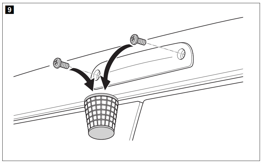
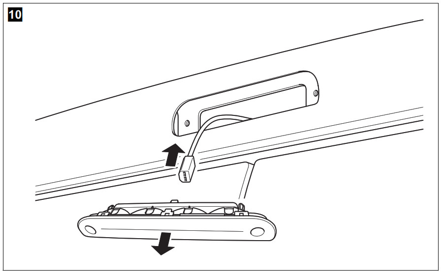
- Dismantling the brake light1. Remove the two screws of the brake light (fig. 9, page 5).2. Remove the plug of the brake light (fig. 0, page 6).
- Laying cables
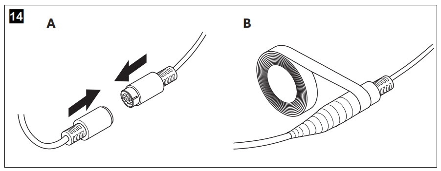
 NOTICE! Beware of damage.• When drilling holes, check beforehand that there is sufficient space on the other side for the drill head to come out.• Cables and connections that are not properly installed will cause malfunctions or damage to components. Correct installation of cables and connections ensures lasting and trouble-free operation of the retrofitted components.• The cables may not be exposed for long periods to solvents such as benzene, since solvents can damage the cable.Therefore, please observe the following instructions:• As far as possible, use original ducts for laying the cables, or other suitable options such as panelling edges, ventilation grilles or dummy plugs. If no openings are available, you must drill holes for the cables. Check beforehand that there is sufficient space on the other side for the drill head to emerge.• Wherever possible, lay cables inside the vehicle, as they are better protected there than outside. If you do need to lay a cable outside the vehicle, ensure that it is well fastened (use additional cable ties, insulating tape etc.).• To prevent damage to the cables when laying them, ensure that they are far enough away from hot or moving vehicle components (exhaust pipes, drive shafts, light systems, fans, heaters, etc.). Use corrugated piping or other protective materials to protect against mechanical wear.Screw on the plug connections for the connecting cables to protect them against water penetration (fig.
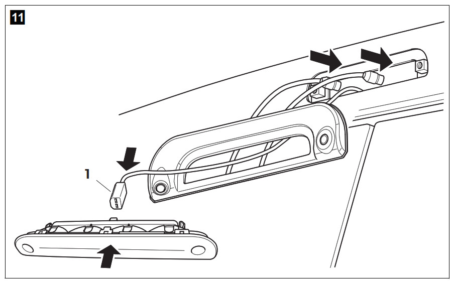
 14, page 7).• When laying the cables, make sure: -they are not kinked or twisted -they do not rub on edges -they are not laid in sharp-edged ducts without protection.• Attach the cables securely in the vehicles to prevent tripping hazards. This can be performed by using cable binders, insulating tape or gluing in place with adhesives.➤ Lay the system cable. - Establishing the electrical connection for the cameraNOTE• Lay the camera cable so that, should you need to remove the camera, you can access the plug connection between the camera and the extension cable easily. This greatly facilitates the disassembly.• To minimise corrosion in the plug, apply a small amount of grease, such as pin grease, in one of the plugs.1. Guide the connector of the brake light through the console.2. Re-attach the plug (fig.
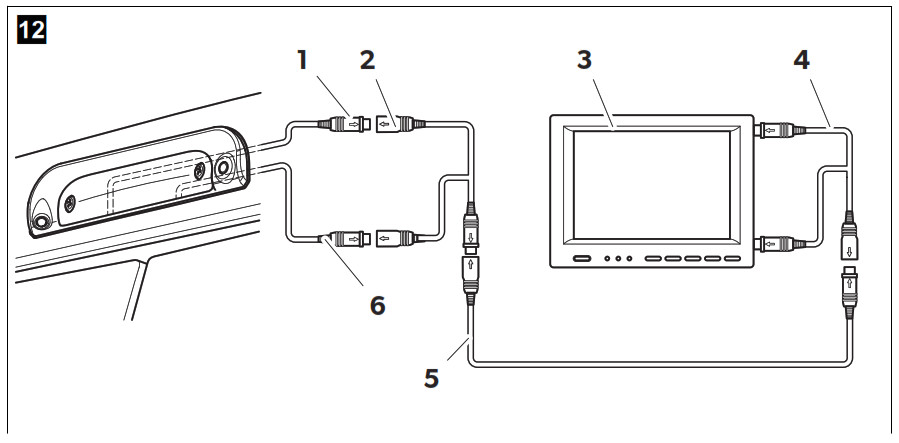
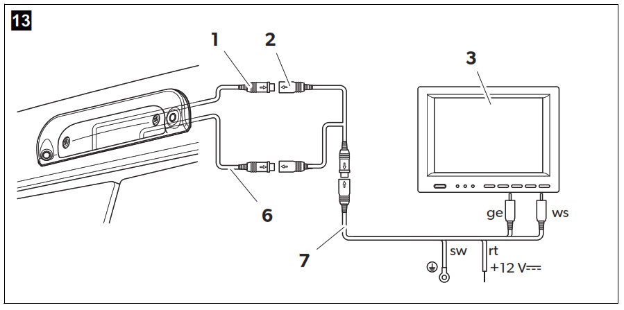
11, page 6) of the brake light onto the brake light.3. Connect the camera as shown in fig.12, page 7 to fig.14, page 7.4. Legend to fig.12, page 7 and fig.13, page 7:Cleaning and caring for the camera
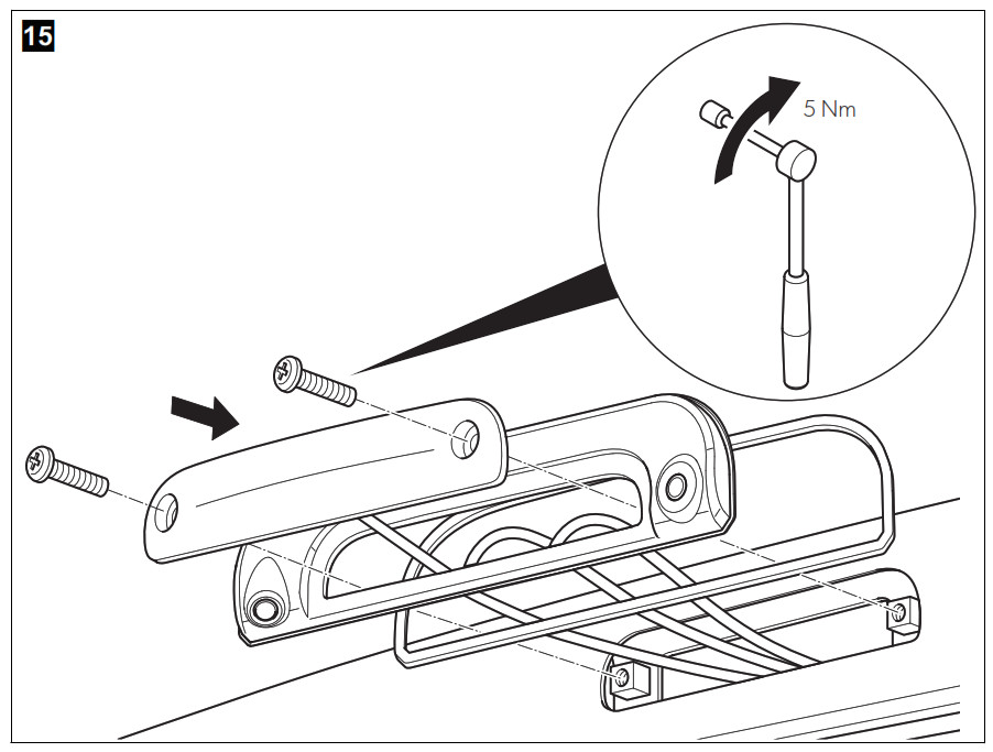
No. Description 1 6-pin connection cable for reversing camera 2 Y-adapter camera 3 Monitor 4 Y-adapter monitor 5 System cable 6 6-pin connection cable for long-distance camera (only CAM35 TWIN) 7 NAV adapter (only CAM35 NAV) Ws white, video signal 1 Ge yellow, video signal 2 Sw black rt red - Fitting the cameraNOTICE! Make sure to guide the camera cables in the console bottom up to the notches so that the cables are not pinched.Proceed as follows (fig.
15, page 8):➤ Secure the brake light and the console with two 6 x 25 mm fastening screws.
Cleaning and caring for the camera
![]() NOTICE! Beware of damage.Do not use any sharp or hard objects for cleaning since they may damage the device.➤ Clean the camera with a soft, damp cloth from time to time.
NOTICE! Beware of damage.Do not use any sharp or hard objects for cleaning since they may damage the device.➤ Clean the camera with a soft, damp cloth from time to time.
Warranty
The statutory warranty period applies. If the product is defective, please contact the manufacturer’s branch in your country (see dometic.com/dealer) or your retailer.
For repair and warranty processing, please send the following items:
- Defect components
- A copy of the receipt with purchasing date
- A reason for the claim or description of the fault
Disposal
➤ Place the packaging material in the appropriate recycling waste bins, wherever possible.
 If you wish to finally dispose of the product, ask your local recycling center or specialist dealer for details about how to do this in accordance with the applicable disposal regulations.
Technical data
|
PerfectView CAM35 REAR |
PerfectView CAM35 REAR NAV |
|
| Ref. no.: |
9102000134 |
9102000133 |
| Image sensor: |
1/4″ CMOS |
|
| Pixels: |
Approx. 345.000 pixels |
|
| Video standard: |
NTSC |
|
| Sensitivity: |
1.5 lux |
|
| Viewing angle: |
Approx. 150°/60° diagonal |
|
| Operating voltage: |
10 V |
|
| Consumption: |
1 W |
|
| Operating temperature: |
–30 °C to +70 °C |
|
| Protection class: |
IP69k |
|
| Vibration resistance: |
10g |
|
| Dimensions W x H x D (with bracket): |
80 x 30 x 33 mm |
|
| Weight: |
Approx. 0.25 kg |
| PerfectView CAM35 TWIN | PerfectView CAM35 TWIN NAV | |
| Ref. no.: |
9102000132 |
9102000131 |
| Image sensor: |
1/4″ CMOS |
|
| Pixels: |
Approx. 345000 pixels |
|
| Video standard: |
NTSC |
|
| Sensitivity: |
1.5 lux |
|
| Viewing angle: |
Approx. 150°/60° diagonal |
|
| Operating voltage: |
10 V |
|
| Consumption: |
1 W |
|
| Operating temperature: |
–30 °C to +70 °C |
|
| Protection class: |
IP69k |
|
| Vibration resistance: |
10g |
|
| Dimensions W x H x D (with bracket): |
80 x 30 x 33 mm |
|
| Weight: |
Approx. 0.25 kg |
Mobile living made easy.![]() dometic.com
dometic.com
| YOUR LOCAL DEALER | YOUR LOCAL SUPPORT | YOUR LOCAL SALES OFFICE |
| dometic.com/dealer | dometic.com/contact | dometic.com/sales-offices |
A complete list of Dometic companies, which comprise the Dometic Group, can be found in the public filings of DOMETIC GROUP AB
References
[xyz-ips snippet=”download-snippet”]