![]()
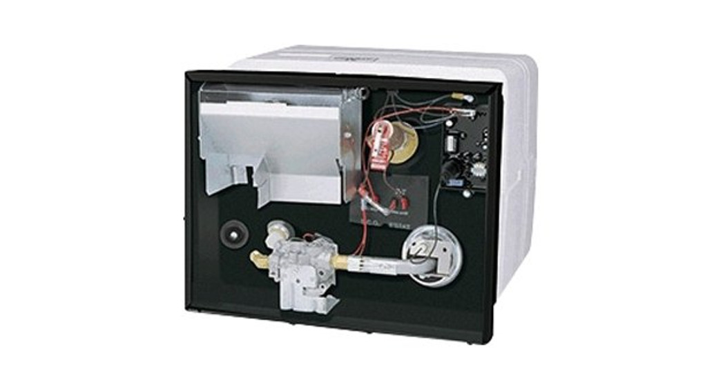
![]() LITERATURE NUMBERMPD 93050L.P. GASWATER HEATER6 & 10 GALLONXT® Models: G9EXT, GE9EXT, GEH9EXTG16EXT, GE16EXT, GEH16EXTPATENT # 7,020,386
LITERATURE NUMBERMPD 93050L.P. GASWATER HEATER6 & 10 GALLONXT® Models: G9EXT, GE9EXT, GEH9EXTG16EXT, GE16EXT, GEH16EXTPATENT # 7,020,386
Dometic XT Water HeatersAdvanced Water Heater System Featuring Exothermal Technology

DOMETIC CORPORATION1120 North Main Street, Elkhart, IN 46514Please Visit: WWW.DOMETIC.COM
This water heater design has been certified by the Canadian Standards Association for installation in recreation vehicles. This water heater is not for use in marine applications.SERVICE CALLS & QUESTIONSLocation and phone numbers of qualified Service Centers can be found at our website http://www.edometic.com or call 866-869-3118 to have a Service Center List mailed.
| SAFETY ALERT SYMBOLSSafety Symbols alerting you to potential personal safety hazards.Obey all safety messages following these symbols. | |
Installation and service must be performed by a qualified Service Technician, Service Center, OEM or Gas Supplier.
DIMENSIONS
| ALL MODEL | WIDTH | HEIGHT | DEPTH |
| 6 GALLON | 16˝ | 12.5˝ | 18.5˝ |
| 10 GALLON | 16˝ | 1505˝ | 21.8˝ |
SHIPPING WT.
| 6 GALLON | 25 lbs |
| 10 GALLON | 32 lbs |
![]() WARNINGFIRE OR EXPLOSION• If the information in this manual is not followed xactly, a fire or explosion may result causing property damage, personal injury or loss of life.
WARNINGFIRE OR EXPLOSION• If the information in this manual is not followed xactly, a fire or explosion may result causing property damage, personal injury or loss of life.
Do not store or use gasoline or other flammable vapors and liquids in the vicinity of this or any other appliance.WHAT TO DO IF YOU SMELL GAS
- Evacuate ALL persons from the vehicle.
- Shut off the gas supply at the gas container or source.
- DO NOT touch any electrical switch, or use any phone or radio in the vehicle.
- DO NOT start the vehicle’s engine or electric generator.
- Contact the nearest gas supplier or qualified Service Technician for repairs.
- If you cannot reach a gas supplier or qualified Service Technician, contact the nearest fire department.
- DO NOT turn on the gas supply until the gas leak(s) has been repaired.
EXPLANATION OF MODEL NUMBER
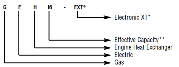
* EXT® indicates Electronic Exothermal (XT) technology.** Water heater’s actual capacity is 6 and10 gallons respectively. Effective capacity, calculated gallons of 130˚F moderated water is 9 gallons and 16 gallons.
INTENTIONALLY LEFT BLANK
![]() CRITICAL INSTALLATION WARNINGS
CRITICAL INSTALLATION WARNINGS
- Install in recreation vehicles only. RVs are recreation vehicles designed as temporary living quarters for recreation, camping, or travel use having their own power or towed by another vehicle.
- All combustion air must be supplied from outside the RV, and all products of combustion must be vented to outside the RV.
- DO NOT vent water heater with venting system serving another appliance.
- DO NOT vent water heater to an outside enclosed porch area.
- Protect building materials from flue gas exhaust.
- Install water heater on an exterior wall, with access door opening to outdoors.
- DO NOT modify the water heater in any way.
- DO NOT alter the water heater for a positive grounding system.
- DO NOT HI-POT water heater unless the electronic ignition system (circuit board) has been disconnected.
- DO NOT use a battery charger to supply power to the water heater even when testing.
USA AND CANADA – FOLLOW ALL APPLICABLE STATE AND LOCAL CODES – IN THE ABSENCE OF LOCAL CODES OR REGULATIONS, REFER TO CURRENT STANDARDS OF:
- Recreation Vehicles ANSI A119.2/NFPA 501C.
- National Fuel Gas Code ANSI Z223.1 and/or CAN/CGA B149 Installation Codes
- Federal Mobile Home Construction & Safety Standard, Title 24 CFR, part 3280, or when this Standard is not applicable, the Standard for Manufactured Home Installations (Manufactured Home Sites, Communities and Set-Ups), ANSI A255.1 and/or CAN/CSA-Z240 MH Series, Mobile Homes.
- National Electrical Code ANSI/NFPA No. 70 and/or CSA C22.1
- Park Trailers A119.5
- CSA Standard Z240 RV Series, Recreational Vehicle.
- ASSE Standard 1017 (Mixing Value).
- NSF Standard ANSI/NSF 14-2003 (All Hoses and Plastic Fittings).
GENERAL INSTALLATION
This is a common installation for water heaters. There are other approved methods such as Flush Mount (MPD 93948) installations. Consult with your Field Auditor, Account Manager, or the Dometic Service Department if you have additional questions.
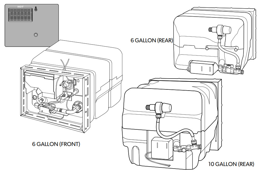
- Locate water heater on floor of coach before erecting sidewalls. The water heater tank must be permanently supported at the same level as the bottom of the sidewall cutout (by the floor or a raised floor) FIG 2. Provide adequate clearance at the rear of the unit for service of water connections.
- To install a water heater on carpeting, you must install the appliance on a metal or wood panel that extends at least three inches beyond the full width and depth of the appliance.
- If the appliance is installed where a connection or tank leakage will damage the adjacent area, install a drain pan (which can be drained to the outside of the coach) under the water heater.
WIRING
All wiring must comply with applicable electrical codes.COMBINATION GAS/ELECTRIC MODELS are designed to operate with gas, electricity, or a combination of both.
- Use electrical metallic tubing, flexible metal conduit, metal-clad cable, or nonmetallic-sheathed cable with a grounding conductor. The wire must have a capacity of 1400 watts or reater. The wiring method must conform to applicable sections of article 551 of National Electrical Code ANSI/NFPA 70.
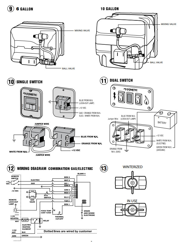
- Refer to Wiring Diagram (FIG 12). Make 120 VAC electricalconnections from the junction box on the back of the unit.a. Connect hot lead to (1) Black.b. Connect common lead to (2) White.c. Connect the ground wire from electrical service to (3) green ground lead in junction box 3.
![]() CAUTIONPRODUCT DAMAGE
CAUTIONPRODUCT DAMAGE
- When using Romex® with a bare earth ground, take care to position ground wire so it does not contact the heating element terminals.
- When a cord and plug connection to the power supply are used on the water heater, the power cord must be UL listed as suitable for damp locations, hard or extra-hard usage. It must be a flexible cord such as type S, SO, ST, STO, SJ, SJT, SJTO, HS or HSO cord as described in National Electrical Code, ANSI/NFPA 70. The length of the external cord to the water heater, measured to the face of the attachment plug, shall be no less than 2 feet nor more than 6 feet. The supply cord must be a minimum of 14 AWG and the attachment plug must be rated at 15 amps.
![]() CAUTIONELECTRICAL DAMAGE
CAUTIONELECTRICAL DAMAGE
- Label all wires before disconnecting when servicing controls.
- Verify proper operation after servicing.
ELECTRONIC IGNITIONNOTE: It is recommended the unit be connected directly to a 12V DC battery or to the filtered side of an AC/DC converter. Avoid connections to the unfiltered side of an AC/DC converter whenever possible. Use a minimum of 18 gauge wire, UL and CSA listed.
- Refer to Wiring Diagram (FIG 12). Install the remote switch in a convenient location. Position wallplate with letters up. Before making connections turn the switch OFF.
- Install wires see FIG 10 & 11.
HEAT EXCHANGE MODELS – FIG 5
- Push a 5/8˝ diameter coolant system hose (5-A) [with SAE 053 A Type “E” clamp attached] onto heat exchanger tube (5-B) making a tight connection.
- Spread hose clamp and slide toward heat exchange unit past annular groove (5-C) and release.
- Continue to HOW TO OPERATE YOUR WATER HEATER and/or Electronic Ignition OPERATION.CONTINUE GENERAL INSTALLATION
- Connect both 1/2˝ NPT water lines (FIG 2) hot water outlet female and cold water inlet female and 3/8˝ flared LP gas line to the water heater (FIG 9).a. Allow flexibility in water and gas lines so you can pull unit forward through the wall one inch past the skin.b. Seal gas line entrance opening (FIG 9) by sliding grommet (9-B) onto 3/8˝ tubing (9-D) before flaring tubing (9-E). Pull gas line and grommet through an opening in housing (9-A). Connect flare fitting (9-C) and press the grommet into the opening. If gas line tubing is already flared, cut the grommet on one side. Place split grommet over the gas line and press it into the opening.c. Always use pipe lubricant on threads when connecting hot and cold water couplings. A suitable plastic fitting is recommended.
 CAUTIONPRODUCT DAMAGEDo not lift, pull, push or misalign the main burner tube (FIG 3-F).
 - Erect side walls and cut opening. See chart and FIG 1.Frame with 2×2 lumber (or equivalent).CUTOUT (FIG 1 & 2)
CAPACITY CUT OUT DIMENSION DEPTH Gallon 1-A 1-B 2-C 6 12-5/8˝ 16-1/4˝ 18.5˝ 10 15-3/4˝ 16-1/4˝ 21.75˝ MINIMUM CLEARANCE FROM COMBUSTIBLE CONSTRUCTION
Sides: 0˝ Top: 0˝ Back: 0˝ Bottom: 0˝ - Bend all flanges 90˚ along scored lines (FIG 3-A).
- To prevent water leaks caulk thoroughly around the opening, including bend slots. Butyl Tape (1-1/3˝x1/8˝) may be substituted for caulking material.
- Push unit against caulking, secure 4-corner brackets (FIG 3-B) to coach with No. 8 – 3/4˝ round head screws (not furnished) or equivalent. Complete the installation by inserting the same type of #8 screws in the holes provided around the flange of the water heater housing. Check all gaskets, they must adhere to the pan creating an air-tight seal.
- Attach access door.a. Snap hinge pin (FIG 3-C) into clip (FIG 3-D).b. Slide cover (FIG 3-E) onto hinge pin.c. Slide hinge pin into cover, snapping into a clip at the same time (FIG 3-D).NOTE: To remove hinge pin, support access cover, and apply force to corner of the hinge pin.
- Disconnect unit and its individual shut-off valve from gas supply line during any pressure testing of the system in excess of 1/2 PSIG (3.4 kPa, 14˝ water column [W.C.]). DO NOT set inlet pressure higher than the maximum indicated on the rating plate of the gas valve (13˝ W.C.). Isolate unit from gas supply line by closing its individual manual shutoff valve during any pressure testing ≤ 1/2 PSIG.WARNINGFIRE AND/OR EXPLOSION• DO NOT use matches, candles, or other sources of ignition when checking for gas leaks.
- Turn on the gas and check the water heater and all connections for gas leaks with a leak detecting solution.
- Fill water heater tank, check all connections for water leaks.
MIXING VALVE – (FIG 9)
![]() WARNINGSCALDING INJURY
WARNINGSCALDING INJURY
- Valve is not serviceable, it must be replaced.
- Replacement by a Certified Service Technician only.
- Tampering with a valve will result in scalding injury.
- Tampering with a valve will void the warranty.
THIS VALVE IS A SAFETY COMPONENT AND MUST NOT BE REMOVED FOR ANY REASON OTHER THAN REPLACEMENT. REMOVAL FOR REPLACEMENT BY A CERTIFIED SERVICETECHNICIAN ONLY. The water heater is equipped with a mixing (moderating) valve which mixes cold water with higher temperature water to moderate outlet water to approximately 130˚F. It is also equipped with a higher temperature thermostat, raising the storage water temperature.PRESSURE-TEMPERATURE RELIEF VALVE – (FIG 3-G)![]() WARNINGSCALDING INJURY
WARNINGSCALDING INJURY
- Valve is not serviceable, it must be replaced.
- Tampering with a valve will result in scalding injury.
- Tampering with a valve will void the warranty.
![]() WARNINGEXPLOSION• DO NOT place a valve, plug, or reducing coupling on the outlet port of the pressure-temperature relief valve.THIS VALVE IS A SAFETY COMPONENT AND MUST NOT BE REMOVED FOR ANY REASON OTHER THAN REPLACEMENT. This water heater is equipped with a temperature and pressure relief valve that complies with the standard for Relief Valves and Automatic Gas Shutoff Devices for Hot Water Systems, ANSI Z21.22.If you use a discharge line, do not use a reducing coupling or other restriction smaller than the outlet of the relief valve. Allow complete drainage of both valve and line.
WARNINGEXPLOSION• DO NOT place a valve, plug, or reducing coupling on the outlet port of the pressure-temperature relief valve.THIS VALVE IS A SAFETY COMPONENT AND MUST NOT BE REMOVED FOR ANY REASON OTHER THAN REPLACEMENT. This water heater is equipped with a temperature and pressure relief valve that complies with the standard for Relief Valves and Automatic Gas Shutoff Devices for Hot Water Systems, ANSI Z21.22.If you use a discharge line, do not use a reducing coupling or other restriction smaller than the outlet of the relief valve. Allow complete drainage of both valve and line.
FOR REPLACEMENT PARTS:
- DO NOT install anything less than a combination temperature-pressure relief valve certified by a nationally recognized testing laboratory that maintains periodic inspection of the product of listed equipment or materials, as meeting requirements for Relief Valves and Automatic Gas Shutoff Devices for Hot Water Supply Systems, ANSI Z21.22. The valve must have a maximum set pressure not to exceed 150 psi.
- Install the valve into the opening provided and marked for this purpose on the water heater.
- Installation must conform with local codes or in the absence of local codes, American National Standard for Recreational Vehicles, ANSI A119.2/NFPA 50IC.
- For an external electrical source, ground this unit in accordance with National Electrical Code ANSI/NFPA70.
Your DOMETIC WATER HEATER is now ready for operation. Continue to HOW TO OPERATE YOUR WATER HEATER.
CONSUMER SAFETY WARNINGS
![]() WARNINGEXPLOSION OR FIRE
WARNINGEXPLOSION OR FIRE
- DO NOT store or use gasoline or other flammable vapors and liquids in the vicinity of this or any other appliance.
- Should overheat occur, or the gas supply fails to shut off, turn gas OFF at the LP tank. On ELECTRONIC IGNITION MODEL turn operating switch to OFF position and remove the red wire from the left-hand terminal of ECO switch or turn gas OFF at the LP tank.
- Use with LP gas only.
- Shut off gas appliances when refueling.
- Turn gas OFF at the LP tank when the vehicle is in motion. This disables all gas appliances. Gas appliances must never be operated while the vehicle is in motion. Unpredictable wind currents may be created which could cause a flame reversal in the burner tube, which could result in fire damage. The thermal cut-off fuse could also be unnecessarily activated resulting in a complete shutdown of the water heater requiring replacement of the thermal cut-off. See maintenance of electronic ignition water heaters for further explanation of the thermal cut-off.
- LP tanks must be filled by a qualified gas supplier only.
HOW TO OPERATE YOUR WATER HEATER
![]() CAUTIONFIRE
CAUTIONFIRE
- Do not smoke or have any flame near an open faucet.If the water heater has not been used for more than two weeks, hydrogen gas may form in the waterline. Under these conditions to reduce the risk of injury, open a hot water faucet for several minutes at the kitchen sink before you use any electrical appliance connected to the hot water system. If hydrogen gas is present, you will probably hear sounds like air escaping through the pipe as the water begins to flow.
![]() WARNINGSCALDING INJURY
WARNINGSCALDING INJURY
- Do not tamper with the orifice or mixing valve.
![]() CAUTIONPRODUCT FAILURE
CAUTIONPRODUCT FAILURE
- Do not operate without water in the tank.
ELECTRONIC IGNITION OPERATION
- Refer to WIRING DIAGRAM FIG12. Place remote switch in ON position.
- For complete shut-down and before servicing:a. Place remote switch in OFF position.b. Remove red wire from left-hand terminal of ECO switch (ECO to valve).
- If the heater fails to operate due to high water temperature, a lockout condition occurs (indicator light on). After the water cools, reset the switch ni OFF position for at least 30 seconds, then turn to the ON position. If a lockout condition persists contact a Dometic Service Center. Read MAINTENANCE AND CARE INSTRUCTIONS & ELECTRONIC IGNITION MAINTENANCE
GAS/ELECTRIC COMBINATION FUNCTIONGAS OPERATION. When the gas switch is turned on, the unit will make three attempts to light. If for any reason there is no ignition, the unit will lockout and the red lockout lamp will illuminate. If the thermostat fails, the ECO will also lock out the unit, requiring resetting. Determine the reason for no ignition, correct it, and reset the gas ignition sequence by turning the switch off, then on.ELECTRIC OPERATION. When the electric switch is turned on, the relay at the rear of the unit will close and pass 110vac to the element. If the thermostat were to fail, the ECO will open and lockout the system. To correct, check the thermostat to assure good contact with the tank and reset the control by turning the electric switch off, then on. GAS/ELECTRIC OPERATION. The unit can be run in both gas and electric modes simultaneously for quick recovery. note: if the gas fails to ignite, the gas mode will lockout, but the lockout lamp will not illuminate since the electric mode is still operational. Should you notice slow recovery, indicating the gas is not working, turn the electric switch off. The lamp will then illuminate indicating a lockout has occurred on the gas side. Correct the problem and turn the switches back on.Read MAINTENANCE AND CARE INSTRUCTIONS.
MAINTENANCE AND CARE INSTRUCTIONS
SERVICE CALLS & QUESTIONSLocation and phone numbers of qualified Service Centers can be found at our website http://www.edometic.com or call 866-869-3118 to have a Service Center List mailed.![]() WARNINGFIRE OR EXPLOSION
WARNINGFIRE OR EXPLOSION
- Shut off the gas supply at the LP container before disconnecting a gas line.
- Keep control compartment clean and free of gasoline, combustible material, and flammable liquids and vapors.
AFTERMARKET WATER HEATING ELEMENT DEVICES![]() WARNINGEXPLOSION / BURN INJURY
WARNINGEXPLOSION / BURN INJURY
- DO NOT alter the water heater, it will void the warranty.
- DO NOT USE Aftermarket heating elements, they can lack critical safety controls.
- The Use of Aftermarket heating elements can lead to out-of-control heating of water tank and a catastrophic wet side explosion.The use of any aftermarket heating element devices may also result in damage to components or water heaters. Dometic’s written warranty states – “failure or damage resulting from any alteration to our water heater is the owner’s responsibility”. Any alteration, like the addition of an aftermarket heating element device, will void the warranty.
GENERAL INFORMATION
- LP and Water system must be turned on.
- Have gas pressure been tested periodically? Should be set at 11 inches of the water column with three appliances running.
- Drain water heater at regular intervals (at least one time during the year).
- Drain water heater before storing RV for the winter or when the possibility of freezing exists.
- Keep vent and combustion air grill clear of any obstructions.
- Periodically, compare flame of main burners with FIG 4 and main burner adjustments in HOW TO OPERATE YOUR WATER HEATER.
- The presence of soot indicates the need to adjust the flame.
ELECTRONIC IGNITION MAINTENANCE
- The water heater comes factory-equipped with a fused circuit board, which will protect the circuit board from wiring shorts. If the fuse should activate, the water heater will not operate. Before replacing the fuse, check for a short external to the board. Once the short is corrected, replace the 2 amp fuse with a mini ATO style fuse. Do not install a fuse larger than 3 amps.
- If the fuse is good and the unit is inoperative, check for excessively high voltage to the unit (more than 14 volts).
- If the previous two steps did not solve the problem, check the thermal cut-off (FIG 3-I). The thermal cutoff is a device installed in the power supply line. This device will shut off the electrical power and stop heater operation when activated. For example, if an obstruction within the flue tube should occur, as described in the Preventative Maintenance section, the burner flame/heat may contact the cutoff, resulting in a melting of the fuse element incorporated in the thermal cutoff. In order to restore power and proper operation of the water heater, the obstruction must be removed and the thermal cutoff must be replaced.
PREVENTATIVE MAINTENANCESpiders, mud wasps, and other insects can build nests in the burner tube. This will cause poor combustion, delayed ignition or ignition outside the combustion tube. Listen for a change in burner sounds or in flame appearance from a hard blue flame to a soft lazy flame or one that is very yellow. These are indications of obstruction in the burnertube (FIG 4-C). Inspect and clean on a regular basis.a. Remove air shutter screw (FIG 4-A) and slide air shutter (FIG 4-B) down burner tube.b. Run a flexible wire brush down the burner tube (FIG 4-D) until it is visible at end of the burner tube.c. Vacuum burner where it enters combustion tube.d. Return air shutter to the original position and replace the screw.e. The orifice, burner tube, and shutter must be aligned so that the shutter is not binding on the air tube.HOW TO CLEAN ELECTRONIC IGNITION MODEL
- Check the main burner orifice.
- Clean and adjust the main burner.
- Main burner and valve manifold must align with each other
- Check electrode for cracked porcelain (FIG 4-E).
- Check electrode for proper gap – 1/8” between electrode and ground.
- If module board functions intermittently, remove board and clean terminal block with a pencil eraser (FIG 3-H).
WATER HEATER TANK CARE![]() WARNINGSCALDING INJURY
WARNINGSCALDING INJURY
- Turn off the water heater and allow time for water to cool before removing the drain plug to flush the tank.
WINTERIZING (FLUSHING) INSTRUCTIONSTo ensure the best performance of your water heater and add to the life of the tank, periodically drain and flush the water heater tank. Before long-term storage or freezing weather drain and flush the tank.
- Turn off the main water supply (the pump or water supply (the pump or water hook up source).
- Drain Water Heater Tank by removing the drain plug. If the water flows sporadically or trickles instead of a steady stream of water, we recommend the following action; first, open the Pressure Temperature Relief Valve to allow air into the tank and secondly, take a small gauge wire or coat hanger and poke through the drain opening to eliminate any obstructions.
- After draining the tank, because of the placement of the Drain Plug, approximately two quarts of water will remain in the tank. This water contains most of the harmful corrosive particles. To remove these harmful corrosive particles flush the tank with either air or water. Whether using air or water pressure, it may be applied through the inlet or outlet on the rear of the tank or the Pressure Temperature Relief Valve. (If using the Pressure Temperature Relief Valve the Support Flange must be removed). The pressure will force out the remaining water and the corrosive particles. If you use water pressure, pump fresh water into the tank with the assistance of the onboard pump or use external water for 90 seconds to allow the fresh water to agitate the stagnant water on the bottom of the tank and force deposits through the drain opening. Continue repeating adding water and draining until the particles have been cleared from the water remaining in the tank.
- Replace the Drain Plug and close the Pressure Temperature Relieve Valve. The approximately two quarts of water remaining in the tank after draining will not cause damage to the tank should freezing occur.
PRESSURE-TEMPERATURE RELIEF VALVE
![]() WARNINGSCALDING INJURY
WARNINGSCALDING INJURY
- Valve is not serviceable, it must be replaced.
- Tampering with a valve will result in scalding injury.
- Tampering with a valve will void the warranty.
![]() WARNINGEXPLOSION
WARNINGEXPLOSION
- Do not place a valve, plug, or reducing coupling on the outlet part of the pressure-temperature relief valve.A Pressure Temperature Relief Valve, dripping while the water heater is running, DOES NOT mean it is defective. During the normal expansion of water, as it is heated in the closed water system of a recreation vehicle, the Pressure Temperature Relief Valve will sometimes drip. The Dometicwater heater tank is designed with an internal air gap at the top of the tank to reduce t e possibility of dripping. In time, the expanding water will absorb this air and it must be restored.
![]() WARNINGSCALDING INJURY
WARNINGSCALDING INJURY
- Turn off water heater before opening the pressure-temperature relief valve to establish air space. Storage water must be cool.
TO REPLACE THE AIR GAP FOLLOW THESE STEPS:
- Turn off the main water supply (the pump or water hook-up source).
- Let the water cool or let run until cool.
- Open the hot water faucet closest to the water heater.
- Pull the handle of the pressure-temperature relief valve straight out and allow water to flow until it stops.
- Allow pressure-temperature relief valve to snap shut; close faucet; turn on the water supply.
- Turn on the water heater and test.
- At least once a year manually operate pressure-temperature relief valve (FIG 3-G).When the pressure-temperature relief valve discharges again, repeat the above procedure. For a permanent solution, we recommend one of the following:
- Install a pressure relief valve in the cold water inlet line to the water heater and attach a drain line from the valve to outside of the coach. Set to relieve at 100-125 PSI.
- Install a diaphragm-type expansion tank in a cold water inlet line. The tank should be sized to allow for expansion of approximately 15 oz. of water and pre-charged to a pressure equal to water supply pressure. These devices can be obtained from a plumbing contractor or Service Center.
FLUSHING TO REMOVE UNPLEASANT ODORA rotten egg odor (hydrogen sulfide) may be produced when the electro galvanic action of the cladding material releases hydrogen from the water. If sulfur is present in the water supply the two will combine and produce an unpleasant smell.
- Turn off the main water supply. Drain the water heater tank and reinstall the drain plug. Remove the pressure-temperature relief valve. Mix solution of 4 parts white vinegar to two parts water. (For a 10-gallon tank, use 6 gallons vinegar to 3 gallons water). With a funnel, carefully pour the solution into the tank.
- Cycle water heater with the above solution, letting it run under normal operation 4-5 times.
- Remove the drain plug and thoroughly drain all water from the tank. Flush the water heater to remove any sediment. you may flush the tank with air pressure or freshwater. Pressure may be applied through either the inlet or outlet valve on the rear of the tank or through the pressure-temperature relief valve coupling located on the front of the unit.TO FLUSH TANK WITH AIR PRESSURE:Insert your air pressure through the pressure-temperature relief valve coupling. With the drain valve open, the air pressure will force the remaining water out of the unit.TO FLUSH TANK WITH WATER PRESSURE:Freshwater should be pumped into the tank with either the onboard pump or external water pressure. Continue this flushing process for approximately five minutes, allowing the freshwater to agitate the stagnant water on the bottom of the tank and forcing the deposits through the drain opening.
- Replace the drain plug and pressure-temperature relief valve.
- Refill tank with fresh water that contains no sulfur.
The Dometic water heater is designed for use in a recreation vehicle. If you use your vehicle frequently or for long periods of time, flushing the water heater several times a year will prolong the life of the storage tank.

FOR IDENTIFICATION AND REPAIR PARTS GO TO:WWW.DOMETIC.COMCHOOSE WATER HEATERS CATEGORY THEN LP XT WATER HEATERSUSE MODEL NUMBER LOCATED ON UNIT TO FIND PARTS
General—Burner Maintenance

- Periodically clear all obstructions in Burner Orifice and pilot Assembly (dirt, spider webs, etc.)
- Periodically clean Burner Tube with a small brush
- Check air adjustment of Burner by positioning the air shutter 1/4 open (blue flame with a small trace of yellow).
- Check Alignment of Burner tube and Orifice—Must be straight
- PILOT MODEL—Check orifice for contamination. Clean if flame is low, replace assembly if cleaning fails.
- ELECTRONIC MODEL—Check electrode for cracks and gap (Spark probe and the Ground gap should be 1/8”)
Tank MaintenanceFailure to follow these instructions May result in Denial of Your Warranty Coverage!Caution! Always turn off the main water supply (pump or water supply hook-up), allow the water to cool, then drain the tank by removing the drain plug.Frequency: Full-Time RV’er, Every (60) day (Southwest US, every (30) day). Part-Time RV’er, Minimum of 2X annually (Southwest, every (90) day).Reason: The Life of the tank and performance of the water heater are directly affected by water quality! High mineral content will cause corrosion and sediment deposits that shorten the life of the tank, element, relief valve, and Mixing Valve (XT Models). (Lack of proper maintenance of the tank will cause Mixing Valves on XT Models to malfunction, requiring costly service procedures to clean and/or replace at the owner’s expense.)Flushing the Tank
- Turn off the main water supply (pump or water hook-up source).
- Drain the water heater by removing the drain plug. If the water flows sporadically or trickles instead of a steady stream, we recommend the following action: First, open the Pressure/Temperature Relief Valve to allow air into the tank and Second, using a small gauge wire or coat hanger, poke through the drain coupling to dislodge any obstructions.
- With the tank drained, approximately two quarts of water remain in the bottom (note drain plug position in the illustration above). This water contains most of the harmful corrosive particles. To remove these materials, Dometic recommends the use of a commercially available “RV Water Heater Flushing Tool”. Simply running water through the inlet does not stir up and flush out all sediment. The wand of a flushing tool allows you to move around at different angles inside the tank with a higher pressure water jet, suspending and flushing the materials back out of the drain coupling. Continue flushing until the water being flushed from the drain coupling runs clear.
- Replace the drain plug.
WinterizingPrior to storing your RV, Follow Steps 1-4 of “Flushing the Tank” above. Note: The approximately (2) quarts of water that remain in the bottom of the tank will not cause freeze damage to the tank. Caution!: An un-drained tank, (water level above the drain plug level), will crack the tank in freezing conditions.Unpleasant OdorsA “rotten egg odor” (hydrogen sulfide) may be produced when the electro galvanic action of the cladding material releases hydrogen from the water. If sulfur is present in the water supply the two will combine and produce an unpleasant smell. To remedy the problem, first complete the (4) steps in “Flushing the Tank” above. When the tank is flushed, perform the following:
- Remove the Pressure/Temperature Relief Valve. Mix a solution of (4) parts white vinegar to (2) parts water. (For a 6-gallon tank, use (4) gallons of vinegar to (2) gallons of water.) With a funnel, carefully pour the solution into the tank through the P&T coupling. Re-install the P&T Relief Valve.
- Turn on the water heater and allow the water to heat up through a full cycle (this may take up to 45 minutes.) It is recommended you allow the waterheater to operate through 3 or 4 additional heat maintenance cycles.
- Turn off and allow to cool. When cool, remove the drain plug and drain. Then repeat Steps 3 and 4 of “Flushing the Tank” above.
- Refill the tank with fresh water that contains no sulfur.
Dripping Pressure Temperature Relief ValveA Pressure Temperature Relief Valve, dripping while the water heater is in use, DOES NOT mean it is defective. During normal use, water expands as it is heated in the closed water system. The Dometic water heater is designed with an internal air gap at the top of the tank to absorb the expansion and reduce the dripping. In time, this air gap will be absorbed and need to be restored. To restore the Air Gap:
- Turn off the main water supply (pump or water hook-up source) and allow water to cool.
- Open the nearest hot water faucet to the water heater.
- Pull the handle on the Pressure Temperature Relief Valve straight out and allow water to flow until it stops flowing.
- Trip the handle on the relief valve allowing it to snap shut, shut off the hot water faucet, turn on the water supply, and turn the water heater on. Test.
XT Models—Special RequirementsIf you experience low flow from the hot water faucet or notice the water is not as hot coming from the water heater, you may have to have the Mixing Valve serviced by a Certified Service Technician. Low flow or cold flow from the XT water heater is a result of corrosion on the seats and/or debris blocking the inlet screen (if equipped) of the mixing valve. When the technician removes the mixing valve, cleans the screen (if equipped), and soaks the valve in a hot white vinegar bath, he will also complete the “Flushing the Tank” procedure as corrosion and sediment from improper “Tank Maintenance” is the cause of this condition.Altering Dometic Water Heaters![]() If the water heater has been altered the Warranty will be Void
If the water heater has been altered the Warranty will be Void![]() Use of Aftermarket Heating Element Devices (Hot Rods) can lead to out-of-control heating of water in the tank and catastrophic wet side explosion. These devices lack critical safety controls. Personal injury and product damage may result. Replacing the Dometic drain plug with an Anode Rod will damage the coupling with cathodic action and product damage will result. Dometic water heater tanks are constructed of high-strength aluminum. The interior of the tank consists of a .0015 thick, type 7072 clad aluminum (pure aluminum and zinc) fused to the core in the rolling process. This material protects the tank from the effects of heavy metals and salts found throughout North America. It is anodic to these heavy metals and acts much like an anode in a steel glass-lined tank, except it lasts much longer.Use of Aftermarket Heating Elements or Anode Devices are not compatible with Dometic Water Heaters and will void the warranty!
Use of Aftermarket Heating Element Devices (Hot Rods) can lead to out-of-control heating of water in the tank and catastrophic wet side explosion. These devices lack critical safety controls. Personal injury and product damage may result. Replacing the Dometic drain plug with an Anode Rod will damage the coupling with cathodic action and product damage will result. Dometic water heater tanks are constructed of high-strength aluminum. The interior of the tank consists of a .0015 thick, type 7072 clad aluminum (pure aluminum and zinc) fused to the core in the rolling process. This material protects the tank from the effects of heavy metals and salts found throughout North America. It is anodic to these heavy metals and acts much like an anode in a steel glass-lined tank, except it lasts much longer.Use of Aftermarket Heating Elements or Anode Devices are not compatible with Dometic Water Heaters and will void the warranty!
LIMITED TWO-YEAR WARRANTY
LIMITED TWO-YEAR WARRANTY AVAILABLE ATWWW.DOMETIC.COM/WARRANTY.IF YOU HAVE QUESTIONS OR TO OBTAIN A COPY OF THE LIMITED WARRANTY FREE OF CHARGE, CONTACT:DOMETIC CORPORATIONCUSTOMER SUPPORT CENTER1120 NORTH MAIN STREETELKHART, INDIANA, USA 46514+1-800-544-4881 OPT 3
References
[xyz-ips snippet=”download-snippet”]