 POWER & CONTROLPERFECTVIEW VIDEO SYSTEMS
CAM1000 / BSC01
© 2021 Dometic Group. The visual appearance of the contents of this manual is protected by copyright and design law. The underlying technical design and the products contained herein may be protected by design, patent, or be patent pending. The trademarks mentioned in this manual belong to Dometic Sweden AB. All rights are reserved.Please read these instructions carefully and follow all instructions, guidelines, and warnings included in this product manual in order to ensure that you install, use, and maintain the product properly at all times. These instructions MUST stay with this product.By using the product, you hereby confirm that you have read all instructions, guidelines, and warnings carefully and that you understand and agree to abide by the terms and conditions as set forth herein. You agree to use this product only for the intended purpose and application and in accordance with the instructions, guidelines, and warningsas set forth in this product manual as well as in accordance with all applicable laws and regulations. A failure to read and follow the instructions and warnings set forth herein may result in an injury to yourself and others, damage to your product, or damage to other property in the vicinity. This product manual, including the instructions, guidelines, and warnings, and related documentation, may be subject to changes and updates. For up-to-date product information, please visit www.dometic.com.
Explanation of symbols
![]() WARNING!Safety instruction: Indicates a hazardous situation that, if not avoided, could result in death or serious injury.
WARNING!Safety instruction: Indicates a hazardous situation that, if not avoided, could result in death or serious injury.![]() CAUTION!Safety instruction: Indicates a hazardous situation that, if not avoided, could result in minor or moderate injury.
CAUTION!Safety instruction: Indicates a hazardous situation that, if not avoided, could result in minor or moderate injury.![]() NOTICE!Indicates a situation that, if not avoided, can result in property damage.
NOTICE!Indicates a situation that, if not avoided, can result in property damage.![]() NOTESupplementary information for operating the product.
NOTESupplementary information for operating the product.
Safety and installation instructions
The following texts are only a supplement to the illustrations on the supplementary sheet. They do not contain the full installation and operating instructions. Please observe the illustrations on the supplementary sheet.Please observe the prescribed safety instructions and stipulations from the vehicle manufacturer and service workshops.Observe the applicable legal regulations.The manufacturer accepts no liability for damage in the following cases:
- Faulty assembly or connection
- Damage to the product resulting from mechanical influences and incorrect connection voltage
- Alterations to the product without express permission from the manufacturer
- Use for purposes other than those described in the operating manual
Note the following instructions during installation:![]() WARNING!
WARNING!
- Secure the parts installed in the vehicle in such a way that they cannot become loose under any circumstances (sudden braking, accidents) and cause injuries to the occupants of the vehicle.
- Do not install the parts anywhere in the vehicle where an airbag may open. This could cause injury if the airbag deploys.
- Inadequate supply line connections could result in short circuits, causing:• Cable fires• The airbag being triggered• Damage to electronic control devices• Electrical malfunctions (indicators, brake light, horn, ignition, lights).
![]() CAUTION!
CAUTION!
- Secure the parts installed in the vehicle in such a way that they cannot become loose under any circumstances (sudden braking, accidents) and cause injuries to the occupants of the vehicle.
- Secure any parts of the system concealed by the bodywork in such a manner that they cannot become loose or damage other parts or cables, or impair vehicle functions (steering, pedals, etc.).
- Always follow the safety instructions of the vehicle manufacturer.Some work (e.g. on retention systems such as the airbag, etc.) may only be performed by qualified specialists.
![]() NOTICE!
NOTICE!
- When working on the electrical system, the batteries must be separated from the vehicle ground. This applies to the main and additional batteries.
- When working on the following cables, only use insulated cable lugs, plugs, and tab sleeves:– 30 (direct input from positive battery terminal)– 15 (connected positive terminal, behind the battery)– 31 (return cable from the battery, ground)– 58 (reversing light)
Do not use porcelain wire connectors.
- Use a crimping tool to connect the cables.
- Screw the cable when connecting cable 31 (earth)• Screw on the cable using a cable lug and gear disc to one of the vehicle’s earth bolts or• Screw the cable to the sheet metal bodywork using a cable lug and a self-tapping screw.Make sure there is a good earth connection.
- If you disconnect the battery, all data stored in all volatile memory will be lost. Data may have to be reset. Please follow the instructions of the respective vehicle manufacturer in this case. You can find instructions for making these settings in the operating manual.
- You can find instructions for making these settings in the operating manual.
- To prevent damage when drilling, make sure there is sufficient space on the other side for the drill head to emerge.
- Deburr all drill holes and treat them with a rust-protection agent.
Observe the following instructions when working with electrical parts:![]() NOTICE!
NOTICE!
- When testing the voltage in electrical cables, only use a diode test lamp or a voltmeter.Test lamps with a bulb consume too much voltage, which can damage the vehicle’s electronic system.
- When making electrical connections, ensure that:• They are not kinked or twisted• They do not rub on edges• They are not laid in sharp-edged through-holes without protection.
- Insulate all connections.
- Secure the cables against mechanical stress with cable binders or insulating tape, for example to existing lines.
- Follow the installation and operating manual for the monitor.
Scope of delivery
See fig. 1
| No. | Quantity | Designation | Reference number |
| 1 | 1 | Camera CAM1000 / BSC01 | 9.6E+09 |
| 2 | 1 | Base | 9.6E+09 |
| 3 | 1 | Buzzer | – |
| 4 | 1 | Camera cable set | 9.6E+09 |
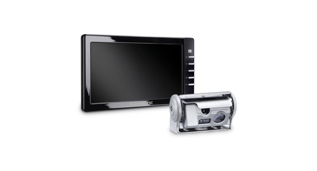
| 5 | 1 | Monitor M75LXAHD (part of system BSV71000) | 9.6E+09 |
| – | 1 | Installation and operating manual |
Intended use
The CAM 1000 / BSC 01 camera, together with the M75LXAHD monitor, is the camera-based turn assistant BVS71000 and supports the driver during right-hand turning maneuvers. The camera is designed for installation above the passenger window of the driver’s cab and is equipped with a movable ball head for easy adjustment.The CAM1000 / BSC01 camera is designed for installation in commercial vehicles.![]() NOTEOnly for Germany and Austria (status of November 2019): CAM1000 / BSC01 may only be operated with the M75LXAHD monitor.
NOTEOnly for Germany and Austria (status of November 2019): CAM1000 / BSC01 may only be operated with the M75LXAHD monitor.![]() WARNING!
WARNING!
- CAM1000 / BSC01does does not release the driver from the duty of care when turning, in particular the inspection of the area to the right of the vehicle.
- The driver remains fully responsible for driving the vehicle, for fulfilling their road safety obligations, and for complying with the statutory road safety requirements.
- Detection reliability depends on correct installation, sufficient care (removal of dirt), and lighting conditions (min. 10 lux).
The CAM1000 / BSC01 camera has the following system limits:
- The system detects moving objects that move from 0° (parallel and in the direction of travel to the vehicle) to about 45° (sideways towards the vehicle).
- The object must move faster than the vehicle.
- The system does not detect any hidden objects.
- The detection of objects in darkness is limited.
- Repeating structures like a construction fence may generate a detection/indication.
- Strong shadows with a behavior similar to moving objects may generate a detection/indication.
This product is only suitable for the intended purpose and application in accordance with these instructions.This manual provides information that is necessary for the proper installation and/or operation of the product. Poor installation and/or improper operating or maintenance will result in unsatisfactory performance and a possible failure.The manufacturer accepts no liability for any injury or damage to the product resulting from:
- Incorrect assembly or connection, including excess voltage
- Incorrect maintenance or use of spare parts other than original spare parts provided by the manufacturer
- Alterations to the product without express permission from the manufacturer
- Use for purposes other than those described in this manual
Dometic reserves the right to change product appearance and product specifications.
Technical description
5.1Function descriptionThe camera image is evaluated via the control unit in the camera. Objects moving in the same direction as the vehicle are detected and marked on the monitor with a movement arrow.The arrow moves with the detected object and serves as an optical signal. Optionally, an acoustic warning signal can be added.The system BVS7 1000 includes the M75LXAHD monitor, which is preferably mounted on the right A-pillar and provides the driver with images of the situation next to the vehicle.The CAM1000 / BSC01 camera has the following features:
- CMOS camera with moving object detection function
- Evaluation of the signal edge when the object enters the active area of the image
- Defined active (
C) and inactive (D) image area (fig.5) - Minimization of messages by the exclusion of irrelevant objects (filtering by direction of movement)
- Optical signaling by dynamic arrow indicator
- Acoustic warning signal
- Speed-dependent activation via GPS receiver
- Automatic activation of the monitor
5.2 Display elements of the camera image
|
Symbol |
Function |
Description |
 |
Active area | The red field marks the detection range of the CAM1000. It appears for about 3 seconds after theignition is switched on. It indicates the area where the camera can detect an object. This field can beused to adjust the camera so that its detection range covers a certain area. |
| Reference line | The reference line appears permanently. It shows the line between active and inactive areas. It shouldpreferably be positioned parallel to the right vehicle contour. | |
 |
Dynamic arrow indicator | The dynamic arrow indication starts at the detected object and moves in the direction of travel of the vehicle (from rear to front). |
| GPS | Green symbol:
Yellow symbol: no GPS signal
Red symbol: no object detection available |
|
| Warning sound | Blue symbol: comfort switching of the buzzer
|
|
|
|
Operation mode | Indication of the selected operation mode |
Installing the CAM1000 / BSC01
See fig. 2 to fig. 06.1Instructions before installation (change acceptance)
- The system BVS71000 – CAM1000/ BSC01 + M75LXAHD with ABE-Nr. KBA91843 requires a change acceptance by a testing laboratory (for example, DEKRA, TÜV).
- Please observe the manufacturer’s installation guidelines.
- The load status has no effect on the function of the system as long as the installation instructions are observed.
- The electrical connection and commissioning may only be carried out by a specialist in accordance with the information in this assembly and operating manual.
- The device may only be put into operation if the user is aware of the risks and dangers resulting from the use of the device.
Supplement to fig. 2 to fig. 8Note the following during installation:
- Note the detection range dependent on the position of the camera:• Operating mode A (red letter “A” on screen) for camera positions with a mounting height from 2m to 3m (fig. 2 to fig. 3):Visible area: 37 m x 6 m, 165° FOV (field of view)Active Area: 8m x 4mOpen cable loop• Operating mode B (red letter “B” on screen) for camera positions with a mounting height from 3m to 4m (fig. 7 to fig. 5):Visible area: 19 m x 8 m, 140° FOV (field of view)Active Area: 8m x 4mClosed cable loop
- Use the extension base if the box body blocks the view to the detection zone (fig. 8).
Supplement to fig. 0
- The system only fulfills the conditions if the monitor is mounted in the area of the right A-pillar (min. 30° to the viewing axis straight ahead).
Connecting the CAM1000 / BSC01
See fig. 11Observe the following:
- As far as possible, use original ducts for laying the cables, or other suitable options such as paneling edges, ventilation grilles, or dummy plugs. If no openings are available, you must drill holes for the respective cables. Check beforehand that there is sufficient space on the other side for the drill head to emerge.
- Wherever possible, lay cables inside the vehicle, as they are better protected there than outside.
- If you do need to lay a cable outside the vehicle, ensure that it is well fastened (use additional cable ties, insulating tape, etc.).
- To prevent damage to the cables when laying them, ensure that they are always far enough away from hot or moving vehicle components (exhaust pipes, driveshafts, light systems, fans, heaters, etc.).
- Attach the cables securely in the vehicles to prevent tripping hazards. This can be performed by using cable binders, insulating tape, or glue in place with adhesives.
- Protect every through-hole made in the bodywork against water penetration by suitable measures, e.g. by using a cable with a sealant and by spraying the cable and the cable sleeve with sealant.
![]() NOTE
NOTE
- In Germany and Austria, special requirements apply for the operation to fulfill the operating license.
- CAM1000 / BSC01 may only be operated with the M75LXAHD monitor.
Key for circuit diagram
|
No |
Designation |
Description |
| 1 | Green connection plug: | Audio output to the loudspeaker |
| 2 | Yellow connection plug: | CVBS video output |
| 3 | Red/black wire: | Buzzer for acoustic signal |
| 4 | Red wire: | Connection to ignition (ACC) 12 V/24 V |
| 5 | Green wire: | R = reverse gear 12 V/24 VOptical indication of objectsWarning sound inactive |
| 6 | White wire: | Left turn signal < 10 seconds:– Optical indication of objects– Warning sound inactiveA blue square appears on the screen.Warning sound switches active– After 3 minutes– Speed > 40 km/h |
| 6.1 | Left turn signal > 10 seconds:– Optical indication of objects– Warning sound inactiveA blue square appears on the screen.Warning sound switches active– With turn off of the left turn signal | |
| 7 | Black wire: | Connection to ground |
| 8 | Yellow/orange wires (to use this trigger wire as a loop 2 cables with the color yellow/orange are needed): | Cable loop for activation of operation mode A or B:Loop open = operating mode A (165° view)Loop closed = operating mode B (140° view) |
| 9 | Blue wire: | GPS output 12 V/24 V for switching on the monitor (blue line) (C3) |
![]() NOTE
NOTE
- In Germany and Austria, special requirements apply for the operation to fulfill the operating license.
- CAM1000 / BSC01 may only be operated with the M75LXAHD monitor.
- It is important for the compliant operation of the system that it cannot be switched off manually. The CAM1000 / BSC01 must therefore be connected via camera input CAM3 of the M75LX AHD monitor. The corresponding blue control line switches the CAM3 (blue wire) off.
The following connections must be implemented:➤ Connect the control cable of the camera system cable (blue) with the blue CAM3 control cable of the monitor. This line is used to switch the monitor on/off.✔ The system will automatically be activated and deactivated via the GPS signal at approx. 40 km/h.➤ Connect the control cable of the monitor and the camera for the reverse gear (green) with the vehicle‘s reverse gear signal.✔ The camera provides an image and object detection is still active, but the warning sound is deactivated.
Using the CAM1000 / BSC01
![]() NOTEOn the initial start-up, the GPS receiver must save the satellite position. This may take up to 5 minutes.8.1 Detection rangeThe detection range of the CAM1000 / BSC01 is divided into two zones:
NOTEOn the initial start-up, the GPS receiver must save the satellite position. This may take up to 5 minutes.8.1 Detection rangeThe detection range of the CAM1000 / BSC01 is divided into two zones:
- Visible area: depending on mounting height in operating mode
AorB - Active Area: 8m x 4m
![]() NOTEThe view of the camera into the detection area must not be obscured by vehicle parts.Objects may not be detected.8.2 Test indicator when switching onSee fig.
NOTEThe view of the camera into the detection area must not be obscured by vehicle parts.Objects may not be detected.8.2 Test indicator when switching onSee fig. b![]() NOTE The video system switches in stand-by mode soon as the ignition is switched on. The system is activated at a speed of less than 40 km/h. The camera image appears. Thered field indicates the active area where detection takes place.The test indicator allows the camera to be correctly aligned with the front of the vehicle. The reference line (fig. 12
NOTE The video system switches in stand-by mode soon as the ignition is switched on. The system is activated at a speed of less than 40 km/h. The camera image appears. Thered field indicates the active area where detection takes place.The test indicator allows the camera to be correctly aligned with the front of the vehicle. The reference line (fig. 12 1) shall be at least in alignment with the front of the vehicle. The active area (fig. 12 2) is marked as a red area in the video for 6 seconds.![]() NOTEIn night mode with ambient lighting below 50 lux, the camera switches to black and white mode. This is necessary to optimize object detection even in poor lighting conditions.The CAM1000 / BSC01 is automatically activated at a speed of less than 40 km/h.As soon as objects move in the same direction and faster as the vehicle, the dynamic arrow indicator (fig. 12
NOTEIn night mode with ambient lighting below 50 lux, the camera switches to black and white mode. This is necessary to optimize object detection even in poor lighting conditions.The CAM1000 / BSC01 is automatically activated at a speed of less than 40 km/h.As soon as objects move in the same direction and faster as the vehicle, the dynamic arrow indicator (fig. 12 3) appears in the display. If the audible signal is connected, an evenly repeating beep will sound.8.3 Operation at day and nightThe monitor M75LXAHD from the BSV71000 system offers adjustment possibilities to adapt the image today and night operation. These settings must be made before connecting the blue wires.
- For more information, please refer to the manual of the monitor M75LXAHD.
Troubleshooting
|
Fault |
Cause |
Solution |
| The device shows no function. | The black or red cable for the voltage supply is not makingcontact. | Check that the connections are secure. |
| The system plug is not connected or not correctly plugged into the control electronics. | Check the system plug and make sure that it locks into place. | |
| “NO SIGNAL” is displayed on themonitor. | No video signal present. Loose contact in the plug connector of the camera cable | Check that the connections are secure. |
| The camera is defective. | Contact an authorized service center to replace the camera. | |
| CAM1000 was not connected to camera input C3. | Make sure that CAM1000 is connected to camera input C3. | |
| A yellow GPS icon appears on the monitor. | GPS reception is faulty. | The system is active but the acoustic warning signal is off until a better GPS reception is obtained. |
| A red GPS icon appears on the monitor. | No object detection is available. | Check that the connections are secure. |
| The monitor will not turn off. | The monitor was turned on manually before connecting the blue lines. In connection with CAM1000, the keys are blocked. | The blue line must be disconnected and the monitor switched off manually. Afterward, connect the blue lines again. |
| No picture, but the warning tone sounds. | The monitor receives no video signal. CAM1000 is connected to the wrong input. | Check the camera channel used. It must be C3. |
| The cinch adapter has a loose contact or is defective. | Check cinch adapter. | |
| Frequent wrong indication at the end of the vehicle when driving right in a curve. | The camera points too far back.Due to the 180° angle of view of the camera, the image moves from back to front and the system also detects non-relevant objects. | Align the camera as perpendicular as possible. The red test field should stop at about 8 m from the front of the vehicle to the rear. |
| Frequent false alarms on uneven surfaces. | Vehicle parts, which move relative to the camera, are captured as an object, e.g. box body. | Find the corresponding vehicle parts (e.g. front edge of the box body) and take them out of the active area by readjusting the camera. Use the reference lines as a tool for this purpose (seealso fig. 13). |
Caring for and maintaining the CAM1000 / BSC01
![]() NOTICE! Damage hazardDo not use sharp or hard objects or cleaning agents for cleaning as these may damagethe product.
NOTICE! Damage hazardDo not use sharp or hard objects or cleaning agents for cleaning as these may damagethe product.
- Occasionally clean the product with a damp cloth.
Warranty
The statutory warranty period applies. If the product is defective, please contact the manufacturer’s branch in your country (see dometic.com/dealer) or your retailer.For repair and warranty processing, please send the following items:
- Defect components
- A copy of the receipt with purchasing date
- A reason for the claim or description of the fault
Disposal
- Place the packaging material in the appropriate recycling waste bins wherever possible.
 If you wish to finally dispose of the product, ask your local recycling center or specialist dealer for details about how to do this in accordance with the applicable disposal regulations.
Technical data
| CAM1000 / BSCO1 | |
| Image sensor: | 1 /3.2 CMOS |
| Resolution: | Approx. 1 million |
| Video format: | NTSC, 1 Vpp |
| Light sensitivity: | <1 lux/0 lux with LED |
| Field of view: | Approx. 180° horizontal Approx. 135° vertical |
| Operating voltage: | 10 V to 36 V |
| Power consumption: | 6 W with LED |
| Operating temperature: | -40 °C to +85 °C |
| Protection dass: | IP69k |
| Dimensions: | 209 x 75 x 58 mm |
| Weight: | Approx. 0.6 kg |
| Tests: | ISO 16750.3ISO 16750-4SAE J2527ECE-R10 05 (2014)E CISPR 25ISO 7637-2FCC Part 15B |
| YOUR LOCAL DEALERdometic.com/dealer | YOUR LOCAL SUPPORTdometic.com/contact |
YOUR LOCAL SALES OFFICEdometic.com/sales-offices |
 report this ad
A complete list of Dometic companies, which comprise the Dometic Group, can be found in the public filings ofDOMETIC GROUP AB Hemvarnsgatan 15 SE-17154 Solna Sweden444510296313/01/2021
References
[xyz-ips snippet=”download-snippet”]