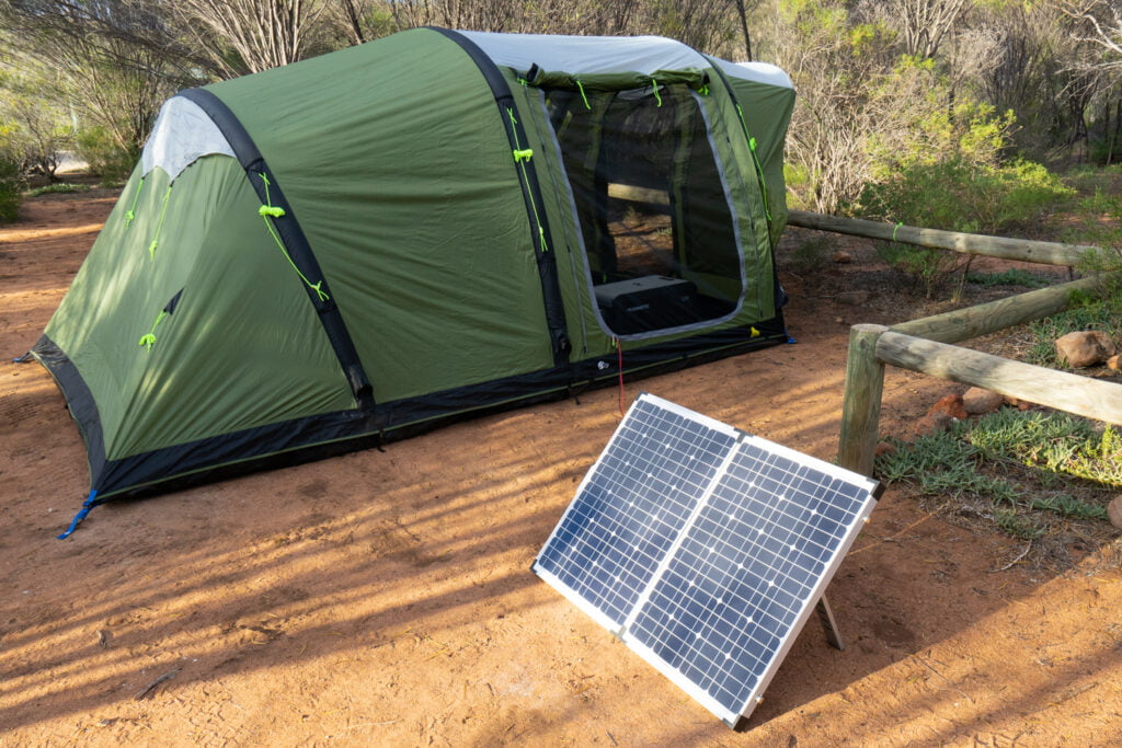
DOMETIC PS120A Portable Solar Kit
Explanation of symbolsPlease read this instruction manual carefully before installation and first use, and store it in a safe place. If you pass on the product to another person, hand over this instruction manual along with it.
Explanation of symbols
![]() WARNING!Safety instruction: Failure to observe this instruction can cause fatal or serious injury.
WARNING!Safety instruction: Failure to observe this instruction can cause fatal or serious injury.
![]() CAUTION!Safety instruction: Failure to observe this instruction can lead to injury.
CAUTION!Safety instruction: Failure to observe this instruction can lead to injury.
 NOTESupplementary information for operating the product.
General safety instructions
The manufacturer accepts no liability for damage in the following cases:
- Damage to the product resulting from mechanical influences and excess voltage
- Alterations to the product without express permission from the manufacturer
- Use for purposes other than those described in the operating manual
The declaration of conformity can be requested from the manufacturer (contact information on the back).Note the following basic safety information when using electrical devices to protect against:
- Electric shock
- Fire hazards
- Injury
General safety
WARNING!
- Only use the device as intended. Any alternation to the product without express permission from Dometic Australia head office avoids warranty.
- Disconnect the device
- Before cleaning and maintenance
- After use
- Before changing a fuse
- The device may not be used if the device itself or connection cables are visibly damaged.
- This appliance may only be repaired by qualified personnel. Inadequate repairs may cause serious hazards.
- This appliance can not be used by children as well as by persons with diminished physical, sensory or mental capacities or a lack of experience and knowledge.
- Electrical devices are not toys.Always keep and use the device out of the reach of children.
- Children must be supervised to ensure that they do not play with the appliance.NOTICE!
- Check the manufacturer‘s data for your battery and ensure that the maximum voltage of the solar charge controller does not exceed the manufacturer‘s recommended charging voltage.
- Do not use the solar panel to charge non-rechargeable batteries.
- Be sure to connect the battery before exposing the solar panel to the sun.
- Before using the device for the first time, check that the voltage specification on the rating plate matches that of the power supply.
- Store the device in a dry and cool place.
Operating the device safely
CAUTION!
- Do not use the solar panel in windy or gusty conditions.
- Do not use high pressure to clean the solar panel.
- Do not operate the device
- In salty, wet or damp environments
- In the vicinity of corrosive fumes
- In the vicinity of combustible materials
- In areas where there is a danger of explosions
NOTICE! Do not disconnect any cables when the device is still in use.
Scope of delivery
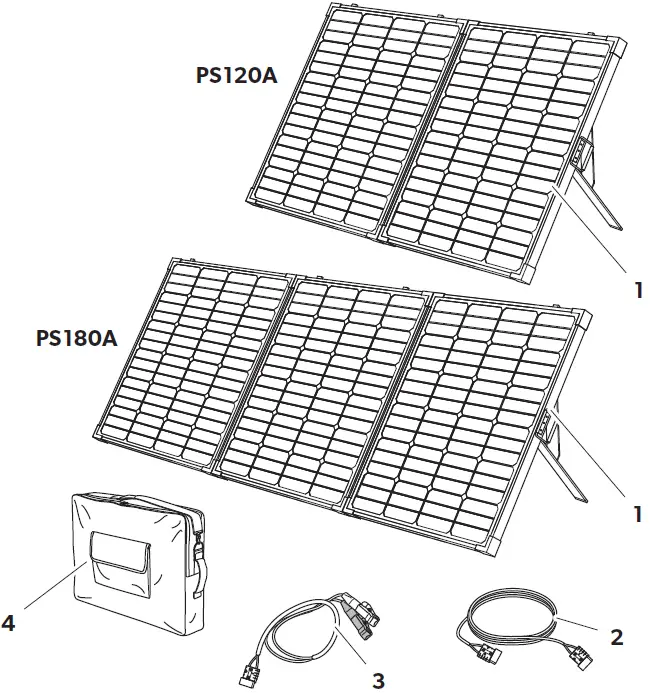
No. in fig.1 Description1 Portable solar panel with solar controller2 5 m cable with Anderson plugs3 Alligator clips adapter4 Carry bag– Temperature sensor– Installation and operating manual
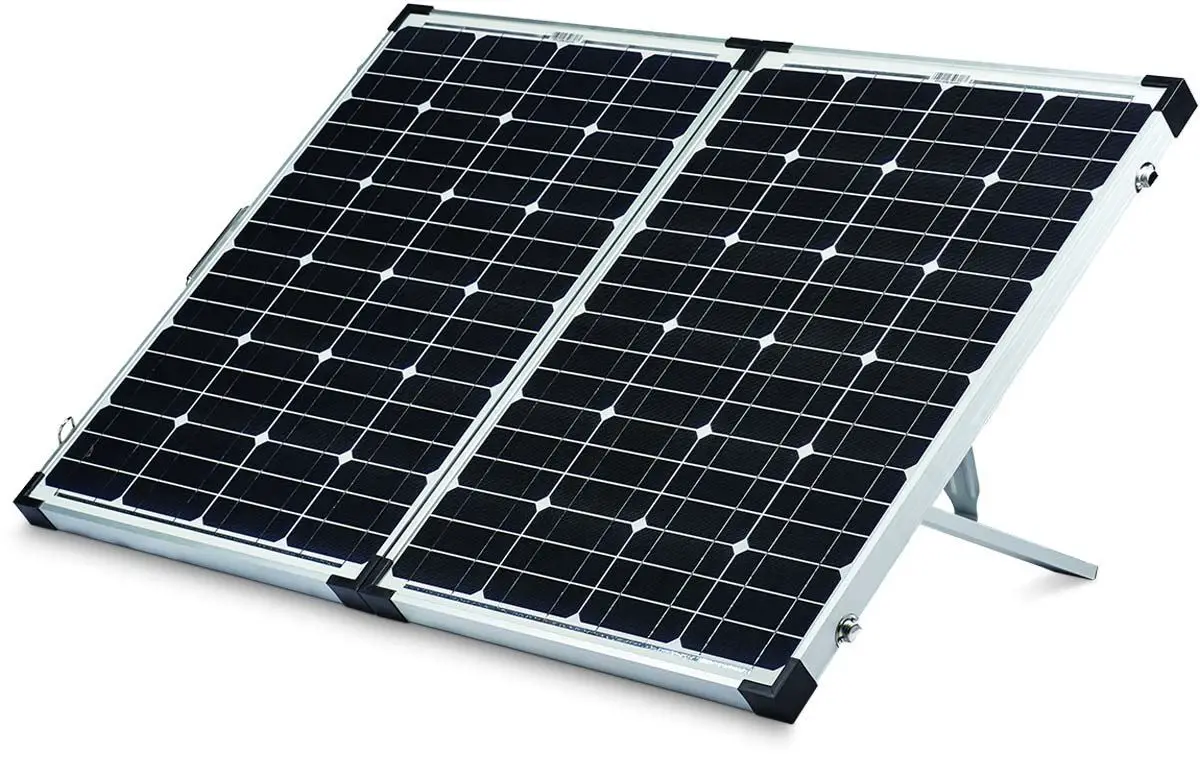
Intended useThe portable solar panel is a mobile power supply with a solar controller attached to the back for charging a 12 Vgbattery and connecting a 12 Vg device.
Technical description
The portable solar panel is designed as monocrystalline construction with tempered glass coating. The integrated solar controller attached to the back enables a DC consumer unit (e.g. a cooler) or inverter to be simultaneously supplied with power while the 12 Vg battery is being charged.The solar controller has the following protective functions:
- Incorrect polarity protection
- Battery overvoltage protection
- Battery undervoltage protection
- Battery open circuit protection
- Battery over-charge and over-discharge protection
- Output overcurrent protection
- Short circuit protections for output and solar panel
- Temperature compensation function
Connecting and display elements
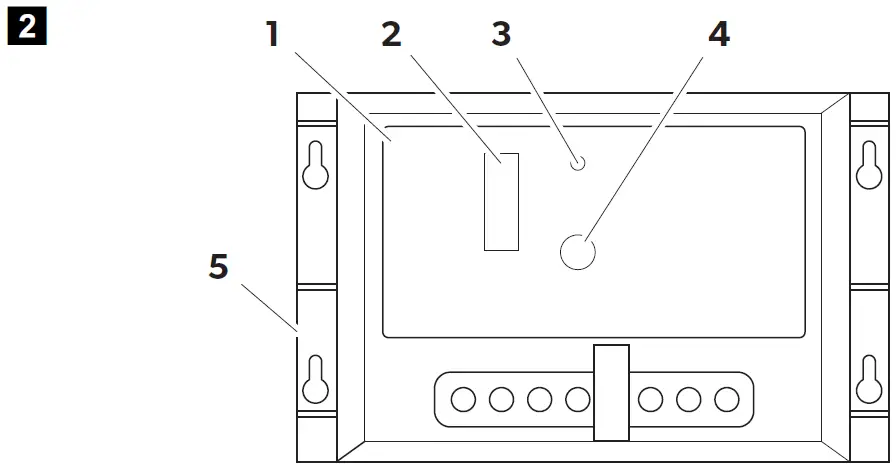
No. in Descriptionfig.2
1 Solar controller
| 2 | Status LEDs | Battery is being charged according to the number of LEDs shinning in cycle: |
| LED 1 = 25% | ||
| LED 2 = 50% | ||
| LED 4 = 75% | ||
| LED 8 = 100% | ||
| LEDs light on when the battery is fully charged. | ||
| 3 | Load LED | The output indicator lights on when an output is present. |
| 4 | Error LED | The error LED lights on when the following faults occur: |
| – Over discharge status | ||
| – Batteries reverse polarity | ||
| – Solar module reserve polarity | ||
| – Load over-current | ||
| – Short current | ||
| – Batteries open circuit working | ||
| 5 | Temperature sensor port |
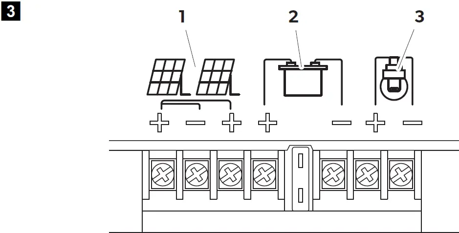
No. in fig.3 Description1 Solar panel terminals2 Battery terminals3 Load terminals
Using the appliance
Positioning the solar panel
NOTE: To obtain maximum output, regularly move the solar panel to track movement of the sun throughout the day.
- Locate a clear area free from over hanging branches or obstructions.
- Remove the solar panel from the carry bag.
- Unclip the latches on the side of the unit and unfold the panel.

- Extend the stands to the required length and lock them in position.

Connecting the solar panel
NOTICE!
- Always observe the following connection sequence.Overvoltage can damage the electronics of the device.
- Connecting the solar panel: Connect the Alligator clips to the battery, then connect the Anderson plug to the solar panel, finally connect the load.
- Disconnecting the solar panel: Disconnect the load first, then disconnect the Anderson plug from the solar panel, finally disconnect the Alligator clips from the battery.
- Ensure that the battery clamps do not get in contact with each other.
- Only use the cable with Anderson plug and alligator clips supplied.
- Make sure that the polarity is correct.
- Make sure that the connection is tight and secure.
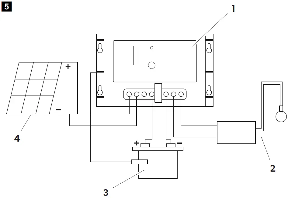
Connecting diagram
Key to connecting diagram
No. in fig.5 Description1 Solar controller2 Load3 12Vg battery4 Solar panel
Connecting to a battery
➤ Connect the Alligator clips to the battery terminals. Connect the red lead with red clamp to the positive (+) battery terminal. Connect the black lead with black clamp to the negative (–) battery terminal. Ensure that the connection is secure and tight.➤ Connect the Anderson plug to the Anderson socket.✓ The battery is loading.✓ The green LEDs on the solar controller light up.The number of green LEDs show the battery capacity. The LEDs light in cycle during charging status. The LEDs stop shinning and light on when the battery is fully charged. In over-discharge status, LED 1 (25%) flashes quickly to warn the user to charge the battery immediately.For safety reasons the solar controller will start buzzing if the battery connection is in reverse polarity to protect against reversing the polarity and short circuits when connecting to a battery.To protect the battery, the solar controller switches off automatically if the voltage is insufficient (see table below).
12 VSwitch-off voltage 11 ± 0.3 VgSwitch-on voltage 12 ± 0.3 Vg
Connecting a 12 Vg device or inverterConnect the lead to the positive (+) and negative (–) terminal. Ensure that the connection is secure and tight.
Connecting the temperature sensorThe battery temperature sensor allows the charge controller to continuously adjust charge voltage based on measured battery temperature.Attach temperature sensor to the battery with tape, ensuring good contact.
Disconnecting the solar panelDisconnect the load first, then disconnect the Anderson plug from the solar panel, finally disconnect the Alligator clips from the battery.
Replacing the fuse
NOTICE! Disconnect the solar panel before you replace the device fuse.
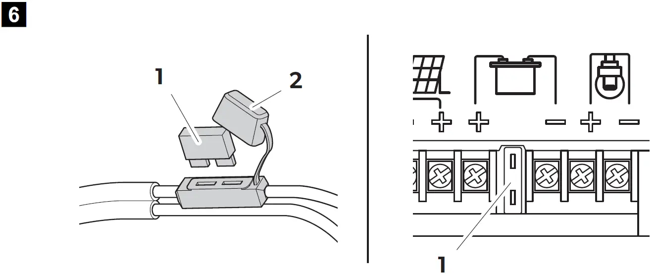
- Disconnect the solar panel.
- Remove the protective cover (2)
- Replace the defective fuse (1) with a new fuse of the same type and rating:
- Cable: 15 A, automotive, fast acting
- Controller: 15 A for PS120A, 20 A for PS180A, automotive, fast acting
- Refit the protective cover.
- Reconnect the power supply to the cooler.
Troubleshooting
If you are unable to rectify the fault, get in touch with a specialist workshop.
| Fault | Possible cause | Suggested remedy |
| Device does not function, LED does not glow. | The device fuse is defective | Replace the device fuse, see chapter “Replacing the fuse” on page 13. |
| The charging LED flashes. | The device is in over discharge status. | Remove the load. Otherwise the device switches of to protect the battery. |
| The fault LED flashes. The | Battery is connected with | Connect the battery with |
| controller buzzes. | wrong polarity. | correct polarity. |
| The fault LED flashes. | Load over-current and short current protection are activated. | Connect the device correctly. |
| Solar module is connected with reserve polarity. | ||
| Batteries circuit open. |
Maintaining and cleaning the product
NOTICE! Do not use sharp or hard objects or cleaning agents for cleaning as these may damage the product.Occasionally clean the surface of the solar panel with a damp cloth.
Warranty
The statutory warranty period applies. If the product is defective, please contact your retailer or the manufacturer’s branch in your country (see the back of the instruction manual for the addresses).For repair and guarantee processing, please include the following documents when you send in the device:
- A copy of the receipt with purchasing date
- A reason for the claim or description of the fault
DisposalPlace the packaging material in the appropriate recycling waste bins wherever possible.If you wish to finally dispose of the product, ask your local recycling centre or specialist dealer for details about how to do this in accordance with the applicable disposal regulations.
Technical data
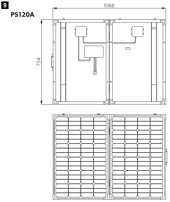
| PS120A | PS180A | |
| Ref. no.: | 9108400883 | 9108400917 |
| Panel type: | Monocrystalline | |
| Peak power: | 120 W ±3% | 180 W ±3% |
| Voltage at max. power (Vmp): | 18.1 V | |
| Current at max. power (Imp): | 6.63 A | 9.95 A |
| Open circuit voltage: | 22.44 V | |
| Short circuit current: | 7.09 A | 10.5 A |
| Operating temperature: | –40 °C to +85 °C | |
| Max. system voltage: | 700 V | |
| In-line fuse: | 15 A, automotive, fast acting | |
| Net weight | 12.25 kg | 17 kg |
| Test condition: | Irradiance 1000 W/m², AM = 1.5 Module temperature 25 °C |
Controller:
| Rated current: | 10 A | 20 A |
| Rated voltage: | 12 Vg | |
| Over-charge protection: | 14.4 ± 0.3 Vg | |
| Over-discharge: Cut-off: Resume: | 11 ± 0.3 Vg
12 ± 0.3 Vg |
|
| Over-voltage: Cut-off: Resume: | 16.5 Vg
15.0 Vg |
|
| Voltage drop:
Between input and batteries: Between batteries and load: |
0.5 Vg
0.2 Vg |
|
| No load current draw: | <5 mA | |
| Ambient temperature: | –10 °C to +55 °C |
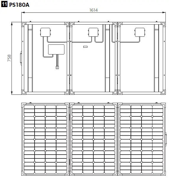
Measurements


AUSTRALIADometic Australia Pty. Ltd.1 John Duncan Court · Varsity Lakes QLD 42271800 212121 · +61 7 55076001Mail: [email protected]
AUSTRIADometic Austria GmbHNeudorferstraße 108A-2353 Guntramsdorf+43 2236 908070+43 2236 90807060Mail: [email protected]
BENELUXDometic Branch Office BelgiumZincstraat 3B-1500 Halle+32 2 3598040+32 2 3598050Mail: [email protected]
BRAZILDometic DO Brasil LTDAAvenida Paulista 1754, conj. 111SP 01310-920 Sao Paulo+55 11 3251 3352+55 11 3251 3362Mail: [email protected]
DENMARKDometic Denmark A/SNordensvej 15, TaulovDK-7000 Fredericia+45 75585966+45 75586307Mail: [email protected]
FINLANDDometic Finland OYMestarintie 4FIN-01730 Vantaa+358 20 7413220+358 9 7593700Mail: [email protected]
FRANCEDometic SASZA du Pré de la Dame JeanneB.P. 5F-60128 Plailly+33 3 44633525+33 3 44633518Mail : [email protected]
GERMANYDometic WAECO International GmbHHollefeldstraße 63D-48282 Emsdetten+49 (0) 2572 879-0+49 (0) 2572 879-300Mail: [email protected]
HONG KONGDometic Group Asia PacificSuites 2207-11 · 22/F · Tower 1The Gateway · 25 Canton Road,Tsim Sha Tsui · Kowloon+852 2 4611386+852 2 4665553Mail: [email protected]
HUNGARYDometic Zrt. Sales OfficeKerékgyártó u. 5.H-1147 Budapest+36 1 468 4400+36 1 468 4401Mail: [email protected]
ITALYDometic Italy S.r.l.Via Virgilio, 3I-47122 Forlì (FC)+39 0543 754901+39 0543 754983Mail: [email protected]
JAPANDometic KKMaekawa-Shibaura, Bldg. 22-13-9 Shibaura Minato-kuTokyo 108-0023+81 3 5445 3333+81 3 5445 3339Mail: [email protected]
MEXICODometic Mx, S. de R. L. de C. V.Circuito Médicos No. 6 Local 1Colonia Ciudad SatéliteCP 53100 Naucalpan de JuárezEstado de México+52 55 5374 4108+52 55 5393 4683Mail: [email protected]
NETHERLANDSDometic Benelux B.V.Ecustraat 3NL-4879 NP Etten-Leur+31 76 5029000+31 76 5029019Mail: [email protected]
NEW ZEALANDDometic New Zealand Ltd.PO Box 12011PenroseAuckland 1642+64 9 622 1490+64 9 622 1573Mail: [email protected]
NORWAYDometic Norway ASØsterøyveien 46N-3232 Sandefjord+47 33428450+47 33428459Mail: [email protected]
POLANDDometic Poland Sp. z o.o.Ul. Puławska 435APL-02-801 Warszawa+48 22 414 3200+48 22 414 3201Mail: info[email protected]
PORTUGALDometic Spain, S.L.Branch Office em PortugalRot. de São Gonçalo nº 1 – Esc. 122775-399 Carcavelos+351 219 244 173+351 219 243 206Mail: [email protected]
RUSSIADometic RUS LLCKomsomolskaya square 6-1RU-107140 Moscow+7 495 780 79 39+7 495 916 56 53Mail: [email protected]
SINGAPOREDometic Pte Ltd18 Boon Lay Way 06–140 Trade Hub 21Singapore 609966+65 6795 3177+65 6862 6620Mail: [email protected]
SLOVAKIADometic Slovakia s.r.o. Sales Office BratislavaNádražná 34/A900 28 Ivanka pri Dunaji+421 2 45 529 680Mail: [email protected]
SOUTH AFRICADometic (Pty) Ltd.Regional OfficeSouth Africa & Sub-Saharan AfricaUnit 6-7 on Mastiff Linbro Park2008 Johannesburg+27 11 4504978+27 11 4504976Mail: [email protected]
SPAINDometic Spain S.L.Avda. Sierra del Guadarrama, 16E-28691 Villanueva de la CañadaMadrid+34 902 111 042+34 900 100 245Mail: [email protected]
SWEDENDometic Scandinavia ABGustaf Melins gata 7S-42131 Västra Frölunda+46 31 7341100+46 31 7341101Mail: [email protected]
SWITZERLANDDometic Switzerland AGRiedackerstrasse 7aCH-8153 Rümlang+41 44 8187171+41 44 8187191Mail: [email protected]
UNITED ARAB EMIRATESDometic Middle East FZCOP. O. Box 17860S-D 6, Jebel Ali FreezoneDubai+971 4 883 3858+971 4 883 3868Mail: [email protected]
UNITED KINGDOMDometic UK Ltd.Dometic House, The BreweryBlandford St. MaryDorset DT11 9LS+44 344 626 0133+44 344 626 0143Mail: [email protected]
USADometic RV Division1120 North Main StreetElkhart, IN 46515+1 574-264-2131
References
[xyz-ips snippet=”download-snippet”]