DOMETIC PT2000-2 Steering System
Pro Trim Installation Guide

![]() WARNING Cancer and Reproductive Harmwww.P65Warnings.ca.gov
WARNING Cancer and Reproductive Harmwww.P65Warnings.ca.gov
Service Center & Dealer LocationsVisit: www.dometic.com
Please read these instructions carefully and follow all instructions, guidelines, and warnings included in this product manual in order to ensure that you install, use, and maintain the product properly at all times. These instructions MUST stay with this product.
By using the product, you hereby confirm that you have read all instructions, guidelines, and warnings carefully and that you understand and agree to abide by the terms and conditions as set forth herein. You agree to use this product only for the intended purpose and application and in accordance with the instructions, guidelines, and warnings as set forth in this product manual as well as in accordance with all applicable laws and regulations. A failure to read and follow the instructions and warnings set forth herein may result in an injury to yourself and others, damage to your product, or damage to other property in the vicinity. This product manual, including the instructions, guidelines, and warnings, and related documentation, may be subject to changes and updates. For up-to-date product information, please visit www.dometic.com.
1 Explanation of Symbols and Safety Instructions
This manual has safety information and instructions to help you eliminate or reduce the risk of accidents and injuries.
1.1 Recognize Safety Information
![]() This is the safety alert symbol. It is used to alert you to potential physical injury hazards. Obey all safety messages that follow this symbol to avoid possible injury or death.
This is the safety alert symbol. It is used to alert you to potential physical injury hazards. Obey all safety messages that follow this symbol to avoid possible injury or death.
1.2 Understand Signal Words
A signal word will identify safety messages and property damage messages, and also will indicate the degree or level of hazard seriousness.
![]() DANGER! Indicates a hazardous situation that, if not avoided, will result in death or serious injury.
DANGER! Indicates a hazardous situation that, if not avoided, will result in death or serious injury.
![]() WARNING Indicates a hazardous situation that, if not avoided, could result in death or serious injury.
WARNING Indicates a hazardous situation that, if not avoided, could result in death or serious injury.
![]() CAUTION Indicates a hazardous situation that, if not avoided, could result in minor or moderate injury.
CAUTION Indicates a hazardous situation that, if not avoided, could result in minor or moderate injury.
NOTICE: Used to address practices not related to physical injury.![]() Indicates additional information that is not related to physical injury.
Indicates additional information that is not related to physical injury.
1.3 Supplemental Directives
To reduce the risk of accidents and injuries, please observe the following directives before installing this product:
- Read and follow all safety information and instructions
- Read and understand these instructions before installing this product
- The installation must comply with all applicable local or national codes, including the latest edition of the following standards:
U.S.A.– ANSI/NFPA70, National Electrical Code (NEC) – American Boat and Yacht Council (ABYC)
1.4 General Safety Messages
WARNING: ELECTRICAL SHOCK OR FIRE HAZARD. Failure to obey the following warnings could result in death or serious injury:
- Use only Dometic replacement parts and components that are specifically approved for use with the product.
- Avoid improper installation, adjustment, alterations, service, or maintenance of the product.
- Do not modify this product in any way. Modification can be extremely hazardous.
2 Intended Use
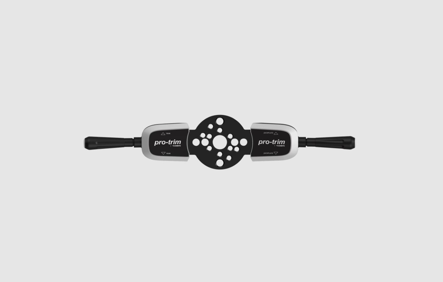
The PRO TRIMTM Single/Dual Bezel Switch Assembly (hereinafter referred to as “switch assembly” or “product”) is designed and intended for installation on a Seater Solutions/Dometic steering helm on a marine craft.The manufacturer accepts no liability for damage in the following cases:
- Faulty assembly or connection
- Damage to the product resulting from mechanical influences and excess voltage
- Alterations to the product
- Use for purposes other than those described in the
operating manual Dometic Corporation reserves the right to modify appearances and specifications without notice.
3 General Information
NOTICE: Use only the hardware provided. Do not substitute.These instructions describe how to install the switch assembly onto the steering helm of a compatible marine craft.
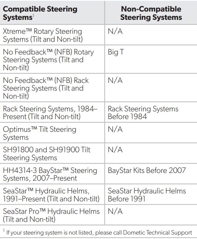
3.1 Compatibility
Before beginning the installation, take a moment to identify your steering system to be sure it is compatible with the switch assembly.
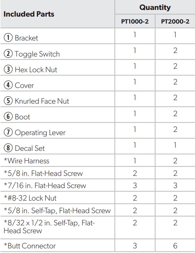
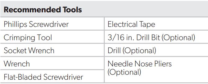
3.2 Components List
![]() The images used in this document are for reference purposes only.
The images used in this document are for reference purposes only.
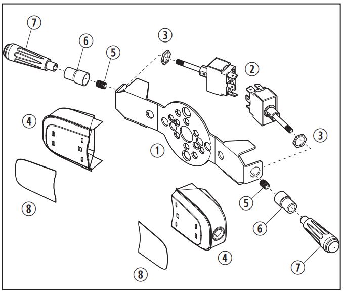
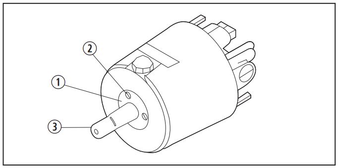
(1) Parts List
4 Wiring Diagram
This section shows the wiring diagram for the switch.
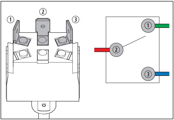
(2) Switch Wiring Diagram
- Top Terminal (Green Wire) (Down)
- Center Terminal (Red Wire) (Power)
- Bottom Terminal (Blue Wire) (Up)
5 Installation
![]() CAUTION: ELECTRICAL SHOCK HAZARDIf drilling through the dash, be sure that the drill will not interfere with any objects such as wires, instrumentation, or brackets on the inside of the dash. Failure to obey this caution could result in minor or moderate injury and property damage.Follow the appropriate section for your steering system for the installation instructions.
CAUTION: ELECTRICAL SHOCK HAZARDIf drilling through the dash, be sure that the drill will not interfere with any objects such as wires, instrumentation, or brackets on the inside of the dash. Failure to obey this caution could result in minor or moderate injury and property damage.Follow the appropriate section for your steering system for the installation instructions.
5.1 Mounting on an Xtreme or No Feedback (NFB) Rotary Steering System (Non-Tilt)
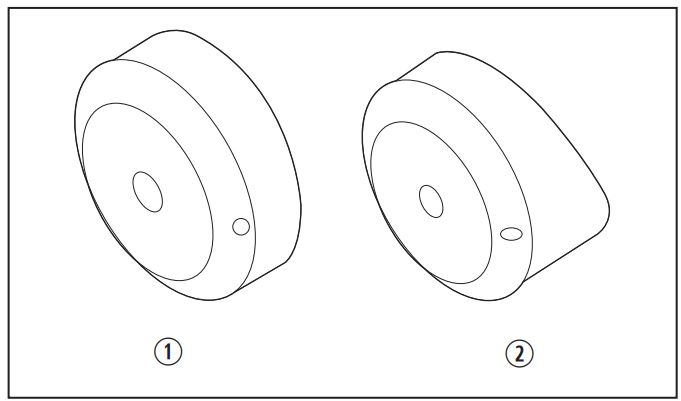
(3) Xtreme and NFB Rotary Steering System Bezels
- NFB and Xtreme Bezel (90° Orientation)
- NFB Bezel (20° Orientation)
The helm of the Xtreme Rotary Steering System (2012 present non-tilt) and the NFB Steering System (1990 present non-tilt) can be identified by the plastic bezel (trim piece) through which the steering wheel shaft passes.
1. Remove the steering wheel and retain the hardware for use during reinstallation. Refer to your steering system and wheel manufacturer instructions to ensure proper removal of the steering components.
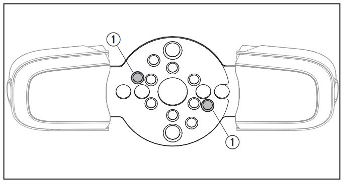
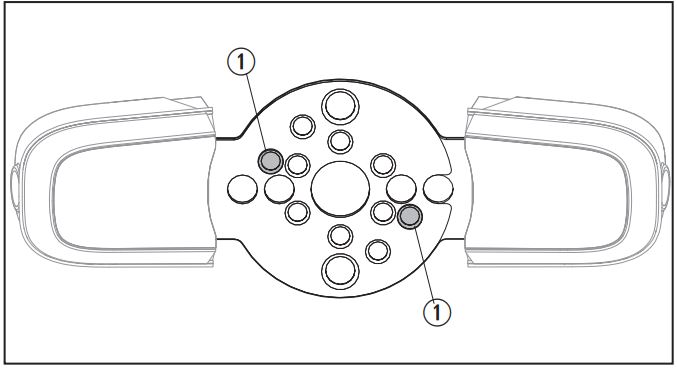
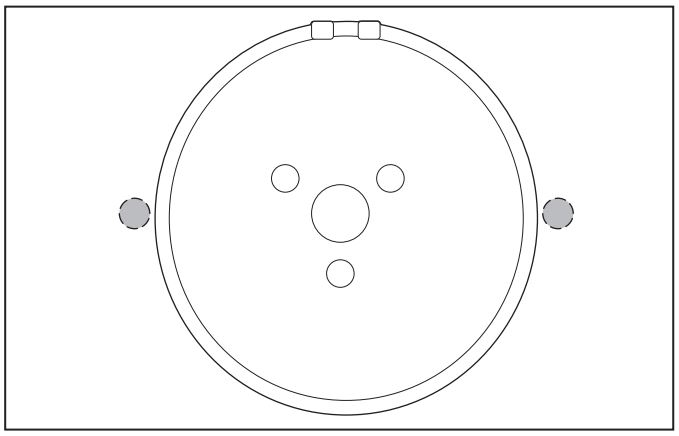
(4) Rotary Steering System Drill Locations
- Rotary Steering System Drill Locations
2. Place the switch assembly bracket against the plastic bezel and mark the holes indicated in Figure 4.3. Drill two 3/16 in. diameter holes where marked on the plastic bezel.
![]() If your bezel already has recessed holes at these locations, then no drilling of the bezel is necessary.
If your bezel already has recessed holes at these locations, then no drilling of the bezel is necessary.
(5) Rotary Steering System Wire Passage–Options 1 and 2 Holes
- Option 1 Holes
- Option 2 Holes
4. Provide a passageway for the wires to the inside or underside of the dash. This can be done one of three ways:
Option 1. Allow the wires to pass through the dash while concealed by the bezel:
- a. Drill one or two 3/8 in. diameter holes (one required for single switch; two required for dual switch) in the beveled face of the bezel.
- b. Drill 3/8 in. diameter holes in the dash.
Option 2. Allow the wires to pass through the dash and not be concealed by the bezel. Drill one or two 3/8 in. diameter holes (one required for single switch; two required for dual switch) through the dash.
Option 3. Allow passage of the wires underneath the dash. Drilling holes is not required.
![]() If installing a single switch, be sure the hole(s) is drilled on the side the switch lever will be installed.
If installing a single switch, be sure the hole(s) is drilled on the side the switch lever will be installed.
5. Attach the wires to the switch; red wire to the center terminal, green wire to the top terminal, and blue wire to the bottom terminal (see Figure 2).
(6) Remove the Bezel
- Bezel
- Countersunk Holes
- Steering Wheel Shaft
6. Remove the bezel from the steering wheel shaft, taking care to leave the attachment screws in the countersunk holes in the bezel.
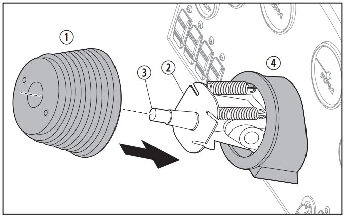
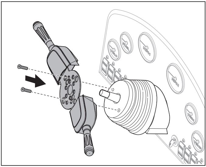
(7) Attach the Bezel
- Bezel
- Switch Assembly
- Screws
- Steering Wheel Shaft
7. Attach the switch assembly to the bezel using the screws provided:a. If the bezel has no recessed holes, use two 7/16 in. screws and lock nuts (provided).b. If the bezel has recessed holes, use two 5/8 in. self-tapping screws (provided).8. Depending on the option chosen in step 4, feed the wires: Through the bezel and dash. Through the dash. Underneath the dash.9. Place the bezel with attached switch assembly over the steering wheel shaft (see Figure 7) and tighten the bezel attachment screws.10. Proceed to “Wiring the Connections to the Marine Craft Device” on page 11.
5.2 Mounting on a Rack Steering System (Non-Tilt)
(8) Rack Steering System Bezels
- Rack Steering System Bezel
- Back Mount Rack Steering System Bezel
The helm of the Rack Steering System (1984present) can be identified by the plastic bezel (trim piece) through which the steering wheel shaft passes.
1. Remove the steering wheel and retain the hardware for use during reinstallation. Refer to your steering system and wheel manufacturer instructions to ensure proper removal of the steering components.
(9) Rack Steering System Drill Locations
- Rack Steering System Drill Locations
2. Place the switch assembly bracket against the plastic bezel and mark the holes indicated in Figure 9.3. Drill two 3/16 in. diameter holes where marked on the plastic bezel.
![]() If your bezel already has recessed holes at these locations, then no drilling of the bezel is necessary.
If your bezel already has recessed holes at these locations, then no drilling of the bezel is necessary.
(10) Rack Steering System Wire Passage–Option 1 Holes
4. Provide a passageway for the wires to the inside or underside of the dash. This can be done one of two ways:
Option 1. Allow the wires to pass through the dash and not be concealed by the bezel. Drill one or two 3/8 in. diameter holes (one required for single switch; two required for dual switch) through the dash.Option 2. Allow passage of the wires underneath the dash. Drilling holes is not required.
![]() If installing a single switch, be sure the hole is drilled on the side the switch lever will be installed.
If installing a single switch, be sure the hole is drilled on the side the switch lever will be installed.
5. Attach the wires to the switch; red wire to the center terminal, green wire to the top terminal, and blue wire to the bottom terminal (see Figure 2).
(11) Remove the Bezel
- Bezel
- Countersunk Holes
- Steering Wheel Shaft
6. Remove the bezel from the steering wheel shaft, taking care to leave the attachment screws in the countersunk holes of the bezel.
(12) Attach the Bezel
- Bezel
- Switch Assembly
- Screws
- Steering Wheel Shaft
7. Attach the switch assembly to the bezel using the screws provided:a. If the bezel has no recessed holes, use two 7/16 in. screws and lock nuts (provided).b. If the bezel has recessed holes, use two 5/8 in. self-tapping screws (provided).8. Place the bezel with attached switch assembly over the steering wheel shaft (see Figure 12) and tighten the bezel screws.9. Proceed to “Wiring the Connections to the Marine Craft Device” on page 11.
5.3 Mounting on a Performance Tilt Steering System

(13) Performance Tilt Steering System Boot and Bezel
- Boot
- Bezel
The Performance Tilt Steering System (1991present) helm can be identified by the grooved rubber boot and plastic bezel attached to the tilt mechanism.
1. Remove the steering wheel and retain the hardware for use during reinstallation. Refer to your steering system and wheel manufacturer instructions to ensure proper removal of the steering components.
(14) Performance Tilt Steering System Drill Locations
- Performance Tilt Steering System Drill Locations
2. If your steering system is the SH91800 or SH91900, then proceed to step 6, as these steering systems have pre-drilled holes.3. Place the switch assembly bracket against the boot, lining up the center holes. Punch mark the holes indicated in Figure 14 through to the tilt mechanism metal mounting flange.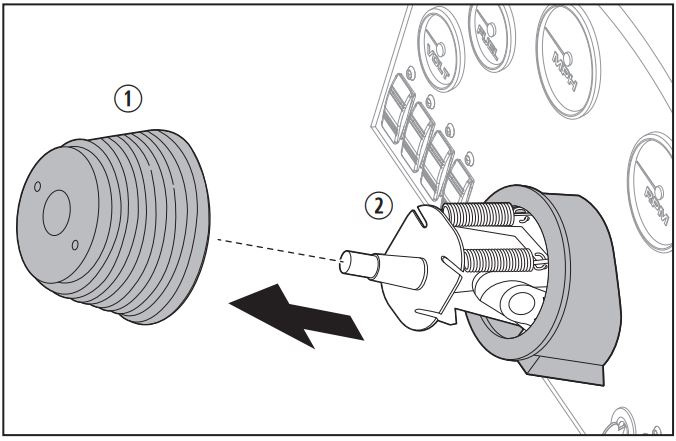
(15) Performance Tilt Steering System Holes in Mounting Flange
- Boot
- Tilt Mechanism
4. Carefully pull to remove the rubber boot.
5. Drill two 3/16 in. diameter holes in the metal mounting flange where marked in Step 3.

(16) Performance Tilt Wire Passage–Option 1 Holes6. Provide a passageway for the wires to the inside or underside of the dash. This can be done one of two ways:
Option 1. Allow the wires to pass through the dash and not be concealed by the bezel. Drill one or two 3/8 in. diameter holes (one required for single switch; two required for dual switch) through the dash.Option 2. Allow passage of the wires underneath the dash. Drilling holes is not required.
![]() If installing a single switch, be sure the hole is drilled on the side the switch lever will be installed.7. Attach the wires to the switch; red wire to the centerterminal, green wire to the top terminal, and blue wire to the bottom terminal (see Figure 2).
If installing a single switch, be sure the hole is drilled on the side the switch lever will be installed.7. Attach the wires to the switch; red wire to the centerterminal, green wire to the top terminal, and blue wire to the bottom terminal (see Figure 2).
(17) Mount the Boot
- Boot
- Tilt Mechanism
- Steering Wheel Shaft
- Bezel
8. Place the tilt mechanism in the middle position.
9. Align the punch marks on the boot with the drilled holes on the metal mounting flange.
10. Install the boot onto the tilt mechanism by doing the following:
- a. Push down completely around the top of the boot to engage it on the metal mounting flange.
- b. Use a rolling motion with your fingers over the corners to ensure that the boot face is resting flush on the metal mounting flange. There is an undercut inside the boot near the face that accepts the edges of the metal mounting flange.
- c. Make sure the boot is flush against the metal mounting flange before proceeding.
- d. Do not attach the boot to the plastic bezel at this time.
(18) Mount the Switch Assembly11. Place the tilt mechanism in the full up position.12. Hold the switch assembly in place against the boot face.13. For the SH91800 tilt unit, secure the switch assembly with two 8/32 x 1/2 in. self-tapping screws (provided). Proceed to step 20.14. Insert one 5/8 in. flat-head screw (provided) into the right side through the assembly switch bracket, boot, and drilled hole of the metal mounting flange. Do not tighten at this time.15. While holding the screw in place, lift the boot from the bottom right side and thread a locknut (provided) onto the flat-head screw. Do not tighten at this time.16. Place the tilt mechanism in the full down position.17. Repeat steps 14 and 15 for the left side screw.18. Place the tilt mechanism in the middle position.19. Align the switch assembly bracket to the steering wheel shaft and boot. Tighten the screws as follows:a. With the tilt mechanism in the full up position, pull the rubber boot up from the bottom at the right side and tighten the locknut.b. With the tilt mechanism in the full down position, pull the rubber boot up from the bottom on the left side and tighten the locknut.20. After fully tightening the screws, follow the instruction manual for your tilt mechanism to learn how to attach the boot to the bezel.21. Work the lip on the rubber boot into the accessory channel on the bezel.22. Proceed to “Wiring the Connections to the Marine Craft Device” on page 11.
5.4 Mounting on a SeaStar or SeaStar Pro Hydraulic Steering System
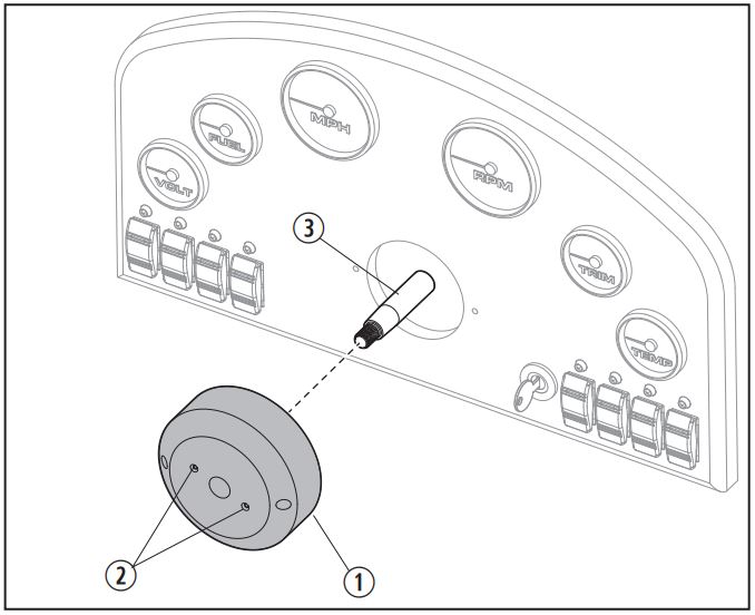
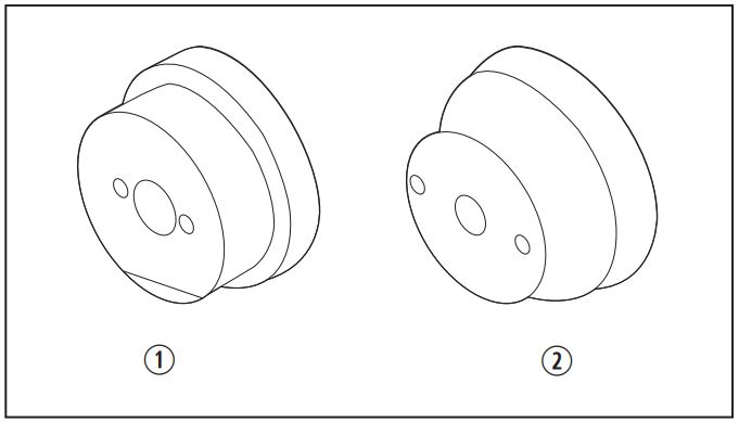
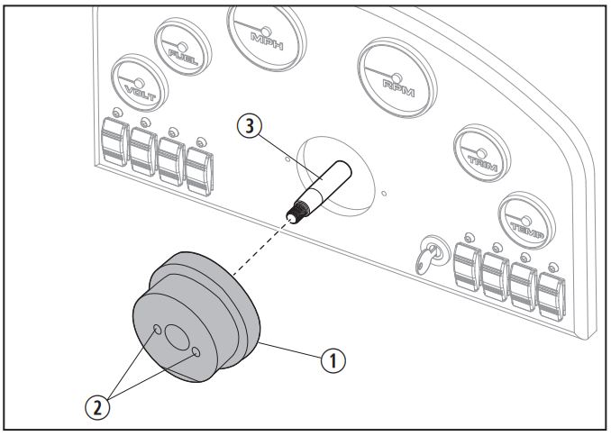
(19) SeaStar and SeaStar Pro Hydraulic Steering System Bezel
- Shaft Seal Retaining Ring
- Countersunk Screws
- Steering Wheel Shaft
The SeaStar and SeaStar Pro Hydraulic Steering System (1991present) helm can be identified by a metallic “SeaStar” decal behind the oil fill plug.
PRO TRIM fits helms with an oil seal retaining ring held by three countersunk screws. This ring is on the front of the helm and surrounds the steering wheel shaft.
If your SeaStar helm does not have the ring with the three screws around the steering wheel shaft, the switch assembly cannot be fitted.
1. Remove the steering wheel and retain the hardware for use during reinstallation. Refer to your steering system and wheel manufacturer instructions to ensure proper removal of the steering components.
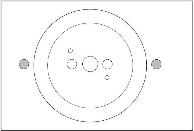
(20) Hydraulic Steering System Wire Passage–Option 1 Holes
2. Provide a passageway for the wires to the inside or underside of the dash. This can be done one of two ways:
Option 1. Allow the wires to pass through the dash and not be concealed by the bezel. Drill one or two 3/8 in. diameter holes (one required for single switch; two required for dual switch) through the dash.Option2. Allow passage of the wires underneath the dash. Drilling holes is not required.
![]() If installing a single switch, be sure the hole is drilled on the side the switch lever will be installed.3. Attach the wires to the switch; red wire to the center terminal, green wire to the top terminal, and blue wire to the bottom terminal (see Figure 2).4. Remove the three countersunk screws that hold the shaft seal retaining ring in place (see Figure 19), but do not remove the shaft seal retaining ring.
If installing a single switch, be sure the hole is drilled on the side the switch lever will be installed.3. Attach the wires to the switch; red wire to the center terminal, green wire to the top terminal, and blue wire to the bottom terminal (see Figure 2).4. Remove the three countersunk screws that hold the shaft seal retaining ring in place (see Figure 19), but do not remove the shaft seal retaining ring.
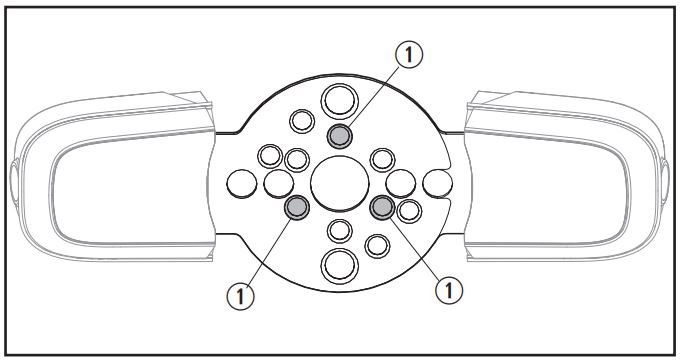
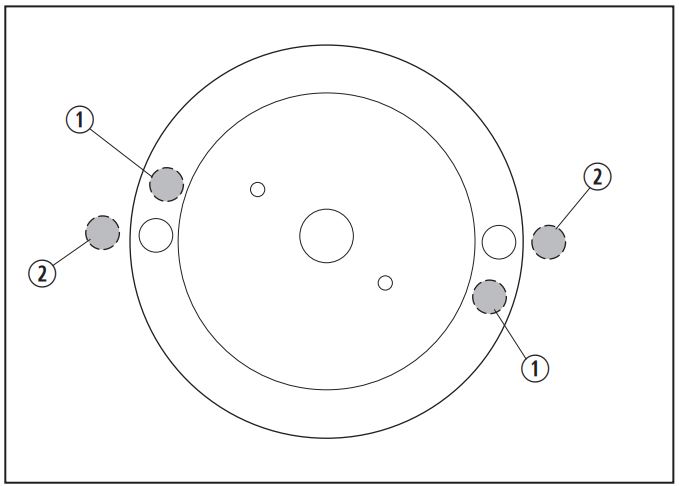
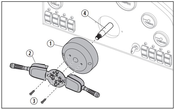
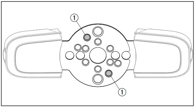
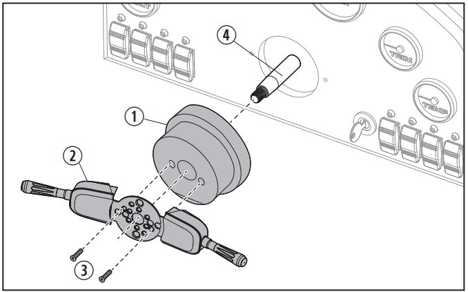
(21) Hydraulic Steering System Mounting Locations
- Hydraulic Steering System Mounting Locations
5. Place the switch assembly over the steering wheel shaft.6. Align the holes in the switch assembly bracket (see Figure 21) with the three holes of the shaft seal retaining ring.7. Attach the switch assembly using three (short) 7/16 in. screws (provided).8. Tighten the screws, alternately and gradually, until all three are tightened securely.9. Proceed to “Wiring the Connections to the Marine Craft Device” below.
5.5 Wiring the Connections to the Marine Craft Device
![]() WARNING: SHOCK HAZARDBefore attempting to make any electrical connections, ensure electrical power is OFF. Failure to do so could result in death or serious injury.
WARNING: SHOCK HAZARDBefore attempting to make any electrical connections, ensure electrical power is OFF. Failure to do so could result in death or serious injury.
![]() CAUTION: SHOCK HAZARDAll wire connections must be secure and sealed to protect from arcing. Failure to do so could result in minor or moderate injury and property damage.The instructions below are for all compatible steering systems.
CAUTION: SHOCK HAZARDAll wire connections must be secure and sealed to protect from arcing. Failure to do so could result in minor or moderate injury and property damage.The instructions below are for all compatible steering systems.
- Disconnect the battery.
- Locate the appropriate existing wires on the marine craft to complete the needed connections.
- See the appropriate wiring instructions below for the device the switch assembly will control:– Wiring for engine trim connection: Engine trim wiring consists of three conductors (1 red, 1 green, 1 blue) running together. Engine trim wires are typically routed from the engine to the side-mounted shift and throttle control. – Wiring for jack plate connection: Jack plate wires are typically found under the dash. Refer to the manufacturer wiring diagrams for the wire colors to properly configure your new switch assembly.– Wiring for horn connection: Horn wires are typically found under the dash. It may be necessary to use a jumper wire on the switch for the horn to operate in both the toggle-up and toggle-down positions. Refer to manufacturer wiring diagrams for the wire colors to properly configure your new switch assembly.
- Feed the switch wires to the inside or underside of the dash, according to the passageway option chosen at installation.
- Make the wire connections to the marine craft by cutting into the marine craft’s trim, jack plate, or horn’s wiring (as appropriate):a. Cut only one wire at a time.b. Strip both ends.c. Use the provided butt connector and insert the two stripped wires from step b into one end of the butt connector and crimp. d. Insert the appropriate color wire from the assembly switch into the other end of the butt connector and crimp.e. If not using the provided butt connector, be sure the butt connector you use will accept:– Two 16-gauge wires on one end – One 16-gauge wire on the other endf. Repeat steps ae (one wire at a time) for the remaining trim, jack plate, or horn wires (as appropriate).
- When all wires are connected, reconnect the battery.
- Test the installation and intended function. (See “Testing the Installation” on page 12 for instructions.)
5.6 Testing the Installation
This section describes the proper procedure to test the installation of the switch assembly.
- When installed for control of engine trim or jack plate operation, make sure the engine moves in the direction you expect when the switch is activated.– Push the lever up to make the engine tilt or move upward. – Push the lever down to make the engine tilt or move downward.
- When installed for horn operation, operate the switch in both directions and check that the horn functions.
- If the switch assembly is not working properly, perform the following checks:a. Check the wire connections at the toggle switch.b. Check the wire connections at the wire harness.
 Go to www.dometic.com to find technical support in your area.
 - If applicable, check the functionality of the marine craft’s original dash or control mounted trim switch to ensure it is still working properly.
- If all systems are working properly, make a final inspection of the wire connections.
- Wrap the wiring assembly with a quality electrical tape (not provided) to keep connections clean and secure.
6 Final Adjustments
This section describes the proper procedure for reinstalling the steering wheel and making any final adjustments to the switch assembly.
6.1 Reinstalling the Steering Wheel
Reinstall the steering wheel using the hardware removed with the steering wheel. Refer to your steering system and wheel manufacturer instructions to insure proper installation of the steering components.
6.2 Adjusting the Lever Distance
![]() Dometic recommends the driver operate the switch assembly lever(s) for a period of time without adjustment until they determine the most suitable lever distance.
Dometic recommends the driver operate the switch assembly lever(s) for a period of time without adjustment until they determine the most suitable lever distance.
- With the seat (and wheel position, if equipped with tilt) adjusted properly, activate the switch from a normal driving grip.
- If the lever seems too close or too far from the steering wheel rim, adjust by carefully bending the bracket (see Figure 1) slightly in the required direction to move the lever closer to or farther from the rim of the steering wheel. Adjust to suit the driver’s preference.
7 Disposal
![]() Place the packaging material in the appropriate recycling waste bins, whenever possible. Consult a local recycling center or specialist dealer for details about how to dispose of the product in accordance with all applicable national and local regulations.
Place the packaging material in the appropriate recycling waste bins, whenever possible. Consult a local recycling center or specialist dealer for details about how to dispose of the product in accordance with all applicable national and local regulations.
8 Warranty Information
LIMITED TWO-YEAR WARRANTY AVAILABLE AT WWW.SEASTARSOLUTIONS.COM/SUPPORT-2/ WARRANTY-2/SEASTAR-SOLUTIONS-WARRANTY.
IF YOU HAVE QUESTIONS, OR TO OBTAIN A COPY OF THE LIMITED WARRANTY FREE OF CHARGE, CONTACT:
DOMETIC CORPORATION : SEASTAR SOLUTIONS 640 NORTH LEWIS ROAD LIMERICK, PENNSYLVANIA 19468 1-610-495-7011 EXT 2[email protected]
Mobile living made easy.
CONTACT USdometic.com/en-us/terms-and-conditions-consumer/contact-us
A complete list of Dometic companies, which comprise the Dometic Group, can be found in the public filings of: DOMETIC GROUP AB Hemvärnsgatan 15 SE-17154 Solna Sweden
References
[xyz-ips snippet=”download-snippet”]