DOMETIC RM5310 Refrigeration 5 Series

RM5310 Refrigeration 5 Series
© 2021 Dometic Group. The visual appearance of the contents of this manual is protected by copyright and design law. The underlying technical design and the products contained herein may be protected by design, patent or be patent pending. The trademarks mentioned in this manual belong to Dometic Sweden AB. All rights are reserved.
Please read these instructions carefully and follow all instructions, guidelines, and warnings included in this product manual in order to ensure that you install, use, and maintain the product properly at all times. These instructions MUST stay with this product.By using the product, you hereby confirm that you have read all instructions, guidelines, and warnings carefully and that you understand and agree to abide by the terms and conditions as set forth herein. You agree to use this product only for the intended purpose and application and in accordance with the instructions, guidelines, and warnings as set forth in this product manual as well as in accordance with all applicable laws and regulations. A failure to read and follow the instructions and warnings set forth herein may result in an injury to yourself and others, damage to your product or damage to other property in the vicinity. This product manual, including the instructions, guidelines, and warnings, and related documentation, may be subject to changes and updates. For up-to-date product information, please visit documents.dometic.com, dometic.com.
Explanation of symbols
 |
WARNING!Safety instruction: Indicates a hazardous situation that, if not avoided, could result in death or serious injury. |
|
CAUTION! Safety instruction: Indicates a hazardous situation that, if not avoided, could result in minor or moderate injury. |
 |
NOTICE!Indicates a situation that, if not avoided, can result in property damage. |
 |
NOTICE!Indicates a situation that, if not avoided, can result in property damage. |
Safety instructions
|
WARNING! Failure to obey these warnings could result in death or serious injury. |
Explosion hazard
- Never open the absorber unit. It is under high pressure and can cause injury if it is opened.
- Only operate the device at the pressure shown on the type plate. Only use pressure controllers with a fixed setting which comply with the national regulations (in Europe EN 12864).
Fire hazard
- Ensure clean and residue-free handling if silicon sealant or similar is used. There is a risk of fire if silicone filaments come into contact with hot parts or naked flames.
- Never use a naked flame to check the device for leaks.
- Only use propane or butane gas (not natural gas).
Health hazard
- Do not operate the device if it is visibly damaged.
- If the AC power cable for this device is damaged, it must be replaced by the manufacturer, a service agent or a similarly qualified person in order to prevent safety hazards.
- This device may only be repaired by qualified personnel. Inadequate repairs may cause serious hazards.
Risk of asphyxiation
- Dismantle all device doors for the disposal of the old device and leave the shelves in the device to prevent accidental enclosure and suffocation.
|
CAUTION! Failure to obey these cautions could result in minor or moderate injury. |
Electrical shock
- Before starting the device, ensure that the power supply line and the plug are dry.
Risk of crushing
- Do not put your fingers into the hinge.
|
NOTICE! Damage hazard |
- Only hold the device at the body of the device during transport. Never hold the device at the absorber unit, the cooling fins, the gas pipes, the door or the control panel.
- Make sure that the device circuit is not damaged during transportation. The refrigerant in the device circuit is highly flammable. In the event of any damage to the device circuit (smell of ammonia): Switch off the device if applicable. Avoid naked flames and sparks. Air the room well.
- Do not install the device near naked flames or other heat sources (heaters, direct sunlight, gas ovens etc.).
- Danger of overheating! Always ensure sufficient ventilation so that the heat generated during operation can dissipate. Make sure that the device is sufficiently far away from walls and other objects so that the air can circulate.
- Check that the voltage specification on the type plate is the same as that of the power supply.
- Do not open the refrigerant circuit under any circumstances.
- Only use the AC connection cable supplied to connect the device to the AC mains.
- Only use cables with a suitable size.
- Never pull the plug out of the socket by the connection cable.
- The device may not be exposed to rain.
Scope of delivery
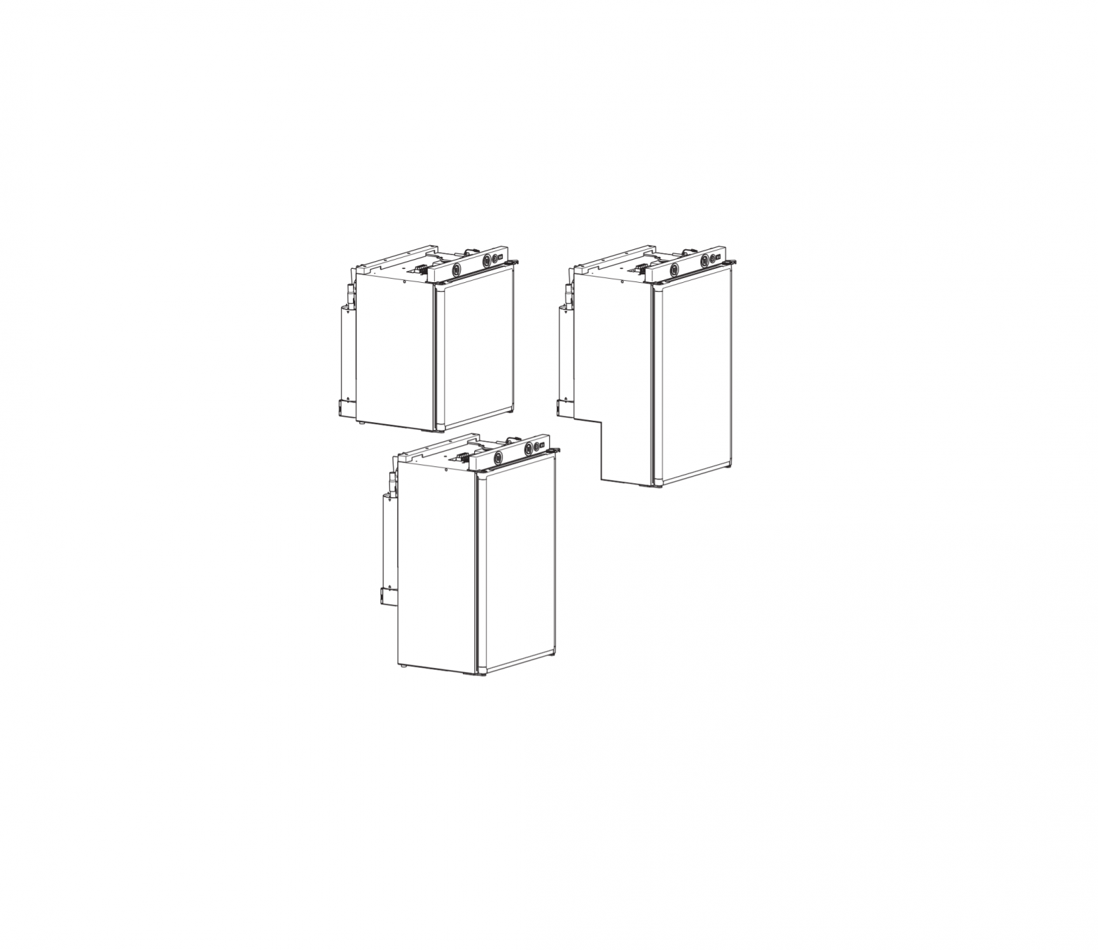
- Refrigerator
- Caps
- Ice-cube tray
- Operating manual
- Installation manual
Accessories
Available as accessories (not included in the scope of delivery):
| Description | Ref. no. |
| Fan kit | 9105900007 |
| LS100 ventilation grille with flue duct and winter cover | |
| White | 9105900012 |
| Beige | 9105900011 |
| LS200 ventilation grille | |
| without flue duct and winter cover | |
| White | 9105900014 |
| Beige | 9105900013 |
If you have questions regarding the accessories, please contact your local service partner.
Intended use
The refrigerator is designed for installation in caravans or motorhomes. It is only suitable for cooling, freezing and storing foodstuffs. The refrigerator is not intended for the proper storage of medicine.
The refrigerator is designed to be operated on a DC power supply and an AC socket and can be powered by liquid gas (propane or butane). The refrigerator may not be run on natural gas or city gas. The RM5385 refrigerator also always requires a permanent DC supply.
This product is only suitable for the intended purpose and application in accordance with these instructions.
This manual provides information that is necessary for proper installation and/or operation of the product. Poor installation and/or improper operating or maintenance will result in unsatisfactory performance and a possible failure.
The manufacturer accepts no liability for any injury or damage to the product resulting from:
- Incorrect assembly or connection, including excess voltage
- Incorrect maintenance or use of spare parts other than original spare parts provided by the manufacturer
- Alterations to the product without express permission from the manufacturer
- Use for purposes other than those described in this manual
Dometic reserves the right to change product appearance and product specifications.
Installing the refrigerator
Preparing the installation
When installing the refrigerator, note the following:
- To enable the refrigerant to circulate properly, the refrigerator may not exceed an angle of 3°. Park the vehicle on a level surface with the help of a spirit level.
- The refrigerator must be installed so that it is easily accessible for service work, easy to de-install and install and can be easily removed from the vehicle.
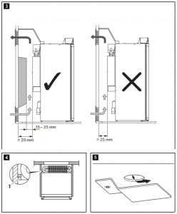
- The distance between the refrigerator and the rear wall must be min. 15 mm max. 25 mm (fig.
 , Check above).
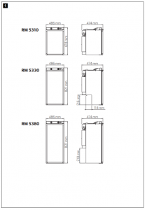
 - The refrigerator must be installed in a recess so that it stands firm when the vehicle is in motion. Note the following dimensions here (H x W x D in mm, fig. Check above): – RM5310: 618 x 486 x 474 – RM5330: 821 x 486 x 474 – RM5380: 821 x 486 x 474
- The outer wall must be fitted with an air inlet vent (fig. Check above) and an outlet vent (fig. Check above) with ventilation grilles so that the heat generated can be easily released to the outside: Air inlet vent: Fit the ventilation grille as flush as possible underneath the burner lid (fig. Check above) with a minimum cross-section of 250 cm2. Outlet vent: fit above the refrigerator as far as possible. A ventilation grille with integrated flue duct can also be used here.
- If the ventilation grille of the air inlet vent cannot be installed flush to the ground, an additional inlet vent (fig. Check above) must be provided in the floor for releasing leaked gas.
- For the RM5380 refrigerators, an air inlet vent (fig. Check above) must always be installed in the floor.
- The air vents must not be covered by vehicle parts (such as an open door or by installing accessories such as bicycle racks) while operating.
- There must be sufficient space at the back of the refrigerator for the air to be able to circulate around the cooling element.
- Fit a heat conduction plate (fig. Check above) above the refrigerator so that the heat does not accumulate in the vehicle.
- Install the refrigerator so that it is protected from excessive heat, as this leads to poor performance and increases the power consumption of the refrigerator.
- The electrical installation must comply with national and local regulations. European standards: EN 60335-1, EN 60335-2-24, EN 1648-1 and EN 1648-2.
- The gas installation must comply with national and local regulations. European standard: EN 1949.
- The refrigerator must be installed in a draught-proof location in accordance with EN 1949, see chapter “Installing the refrigerator in a draught-proof location” Down below.
Installing the refrigerator in a draught-proof location
Gas-powered refrigerators in caravans or motorhomes must be installed in a draught-free location according to EN 1949. This means that the combustion air is not extracted from the interior and the exhaust fumes are prevented from directly entering the living space.
A suitable seal must be fitted between the rear panel of the refrigerator and the interior of the vehicle.
|
WARNING! Fire hazard!Do not use flammable materials such as silicone sealants, foam or similar for the draught-proof installation. |
The manufacturer recommends using a flexible seal to ease removal and installation for maintenance purposes.
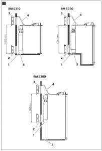
- Attach the sealing lips (fig. Check above) to a stop rail behind the refrigerator, for example, by using an adhesive.
- When installing, push the refrigerator against the stop rails with the sealing lips. This then seals the space behind the refrigerator to the interior of the vehicle.
Creating the air vents
|
NOTEAt high ambient temperatures, the refrigerator can only provide its maximum cooling capacity if the optimum ventilation has been provided. |
- Make an air inlet vent and an air outlet vent in the outer wall with the size of 451 mm x 156 mm. When doing so, observe the information, see chapter “Preparing the installation” Above.If the ventilation grille of the air inlet vent cannot be installed flush with the floor of the niche, you need to install an inlet vent in the floor:
- Make an air inlet vent in the floor (fig.Check above) behind the refrigerator near the gas burner with a diameter of at least 40 mm. The vent pipe must lead directly outside. This allows leaking unburned gas to escape outside.
- Shield the end of the opening with a deflector to prevent sludge or dirt from getting inside while driving (fig., Check above).
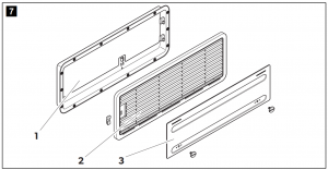
Installing the ventilation grille
LS100
| No. in fig. |
Description |
| 1 | Installation frame |
| 2 | Ventilation grille |
| 3 | Attachment for flue duct |
| 4 | Winter cover |
LS 200
| No. in fig. |
Description |
| 1 | Installation frame |
| 2 | Ventilation grille |
| 3 | Winter cover |
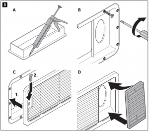
Proceed as follows (fig.![]() Check above):
Check above):
- Ensure the installation frame is water resistant (A).
- Insert the installation frame and screw it down tightly (B).
- Insert the ventilation grille and lock it in place (C).
For LS100 only
Insert the attachment for the flue duct (D).
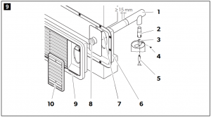
Installing the flue duct
- Proceed as follows (fig.Check above):
- Place the T-piece (1) on the adaptor (2) and the flue pipe (3). Attach the T-piece, adaptor and flue pipe with a screw (4).
- Make sure that the heat distributor (5) is fitted in its intended position. Insert the flue duct with the cover plate (7) through the intended opening in the installation frame (6).
- Connect the flue duct and the cover plate with the T-piece (1).
- Shorten the flue duct (7) to the correct length if necessary.
- Place the LS100 ventilation grille (9) in the installation frame (6) and lock it into place.
- Insert the cover cap (8) onto the flue pipe (7).
- Place the attachment for the flue duct (10) in the ventilation grille (9).
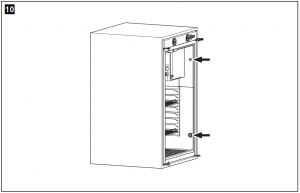
Securing the refrigerator
|
CAUTION!Only drill through the receptacles provided, otherwise foamed components, including cables, can be damaged. |
|
NOTEAttach the side walls or the attached strips so that the screws are tight, even when under increased loads (while driving). |
- Move the refrigerator into its final location.
- Fasten the four screws through the four plastic washers in the sides of the refrigerator (fig. Check above), and further into the wall.
Reversing the door
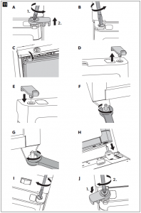
Rotary door lock Replace the door as shown (fig.![]() Check above).
Check above).
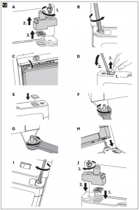
2-button door lock
Replace the door as shown (fig.![]() Check above).
Check above).
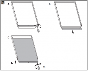
Put on the door panel
|
NOTICE! Beware of damageOnly ever lay the refrigerator on its side and never on its back. Otherwise the unit may be damaged. |
The door panel must have the following dimensions:
- RM5310: 534 x 455 x max. 3 3.8 (H x W x D in mm)
- RM5330/RM5380: 740 x 455 x max. 3 3.8 (H x W x D in mm)
- Put on the door panel as shown (fig, page 11).
Connecting the refrigerator
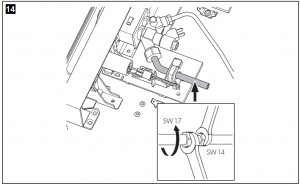
Connecting to the gas supply
|
NOTICE!
|
|
NOTEThe refrigerator is equipped for a connection pressure of 30 mbar. Use a Truma VDR 50/30 back-pressure regulator when connected to a 50 mbar system. |
It must be possible to shut off the refrigerator from the gas line separately by means of a shut-off device. The shut-off device must be easily accessible.
- Connect the refrigerator to the gas supply securely and without any voltage according to fig. Check above. The following applies for Europe: Use a cutting ring fitting in accordance with EN 1949. A hose connection is not permitted.
- Have a leak test and a flame test performed in accordance with EN 1949 by an authorised specialist.Ensure you are issued with a certificate of inspection.
Connecting to 12 V and 230 V∼
|
NOTICE!
|
|
NOTE
|
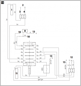
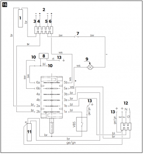
- Connect the RM5310/RM5330/RM5380 refrigerators according to fig. Check above (without lighting), and fig. Check above (with lighting):
| Item | Description |
| 1 | Heating element DC |
| 2 | DC connection cable |
| 3 | Terminal strip for the DC power supply of the heating cartridge |
| 4 | Positive cable of the heating cartridge |
| 5 | Earth cable of the heating cartridge |
| 6 | Positive cable of the lighting |
| 7 | Reed contact switch (sensor switch) |
| 8 | Galvanometer |
| 9 | LED lighting |
| 10 | Thermal power adapter |
| 11 | Heating element AC |
| 12 | AC power connection cable |
| 13 | Housing earth (upper section) |
AC power
- Connect the refrigerator with the mains plug to an AC socket.
DC power
Please note the following cable sizes: – < 6 m (interior): 4 mm2 – > 6 m (interior): 6 mm2 – Connections D+ and S+: 1 mm2 – Cable fed via drawbar (caravans only): 2,5 mm2
- Secure the power supply line to the heating element (connections 3 and 4) with a 15 A fuse and the supply for lighting/electronics (connections 5 and 6) with a 2 A fuse.
- Connect the heating element (connections 3 and 4) with the shortest possible cable.
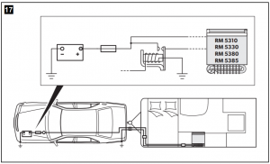
- Run the cable to the heating element (connections 3 and 4) via a relay controlled by an ignition socket to prevent the vehicle battery from completely discharging if the engine is switched off accidentally (fig. Check above).
Cleaning and maintenance
|
WARNING!Always disconnect the refrigerator from the mains before you clean and service it. |
|
NOTICE! Beware of damage
|
- Occasionally clean the refrigerator interior and exterior with a damp cloth.
- Make sure that the air vents on the refrigerator are free of any dust and dirt so that heat can be released and the refrigerator is not damaged.
Warranty
The statutory warranty period applies. If the product is defective, please contact the manufacturer’s branch in your country (see dometic.com/dealer) or your retailer.For repair and warranty processing, please include the following documents when you send in the device:
- A copy of the receipt with purchasing date
- A reason for the claim or description of the fault
Disposal
- Place the packaging material in the appropriate recycling waste bins, wherever possible.
 |
If you wish to finally dispose of the product, ask your local recycling center or specialist dealer for details about how to do this in accordance with the applicable disposal regulations. |
Technical data
|
RM5310 |
RM5330 |
RM5380 |
|
| Voltage: |
230 V |
||
| Gross capacity: |
60 l |
70 l |
80 l |
| Net capacity: |
55 l |
65 l |
75 l |
| Connection value: |
125 W (230 V∼)120W (12 V |
||
| Ice compartment: |
5 l |
||
| Power consumption: |
2.5 kWh/24 h (230 V)240 Ah/24 h (12 V) |
||
| Gas consumption: |
270 g/24 h |
||
| Climatic class: |
SN |
||
| Ambient temperature: |
+10 °C to +32 °C |
||
| Ignition: |
Manual |
Manual |
Manual |
| Power choice: |
Manual |
Manual |
Manual |
| Dimensions: |
fig. |
||
| Weight: |
20 kg |
22 kg |
24 kg |
| Inspection/certification: |  |

References
[xyz-ips snippet=”download-snippet”]