
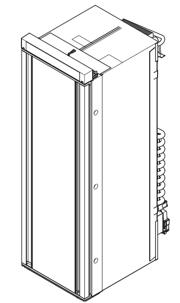
DOMETIC RML 10.4 Slim Left Right Absorber Refrigerator
© 2021 Dometic Group. The visual appearance of the contents of this manual is protected by copyright and design law. The underlying technical design and the products contained herein may be protected by design, patent or be patent pending. The trademarks mentioned in this manual belong to Dometic Sweden AB. All rights are reserved.
Please read these instructions carefully and follow all instructions, guidelines, and warnings included in this product manual in order to ensure that you install, use, and maintain the product properly at all times. These instructions MUST stay with this product.By using the product, you hereby confirm that you have read all instructions, guidelines, and warnings carefully and that you understand and agree to abide by the terms and conditions as set forth herein. You agree to use this product only for the intended purpose and application and in accordance with the instructions, guidelines, and warnings as set forth in this product manual as well as in accordance with all appli-cable laws and regulations. A failure to read and follow the instructions and warnings set forth herein may result in an injury to yourself and others, damage to your product or damage to other property in the vicinity. This product manual, including the instructions, guidelines, and warnings, and related documentation, may be subject to changes and updates. For up-to-date product information, please visit dometic.com
Safety instructions
WARNING! Failure to obey these warnings could result in death or serious injury.
Explosion hazard
- Never open the absorber unit. It is under high pressure and can cause injury if it is opened.
- Only operate the device at the pressure shown on the type plate. Only use pressure controllers with a fixed setting which comply with the national regulations (in Europe EN 12864).
Fire hazard
- Ensure clean and residue-free handling if silicon sealant or similar is used. There is a risk of fire if silicone filaments come into contact with hot parts or naked flames.
- Never use a naked flame to check the device for leaks.
- Only use propane or butane gas (not natural gas).
Health hazard
- Do not operate the device if it is visibly damaged.
- If the AC power cable for this device is damaged, it must be replaced by the manufacturer, a service agent or a similarly qualified person in order to prevent safety hazards.
- This device may only be repaired by qualified personnel. Inadequate repairs may cause serious hazards.
Risk of asphyxiation
- Dismantle all device doors for the disposal of the old device and leave the shelves in the device to prevent accidental enclosure and suffocation.
- Before starting the device, ensure that the power supply line and the plug are dry.
- Do not put your fingers into the hinge.
NOTICE! Damage hazard
- Only hold the device at the body of the device during transport. Never hold the device at the absorber unit, the cooling fins, the gas pipes, the door or the control panel.
- Make sure that the device circuit is not damaged during transportation. The refrigerant in the device circuit is highly flammable.In the event of any damage to the device circuit (smell of ammonia):– Switch off the device if applicable.– Avoid naked flames and sparks.– Air the room well.
- Do not install the device near naked flames or other heat sources (heat-ers, direct sunlight, gas ovens etc.).
- Danger of overheating!Always ensure sufficient ventilation so that the heat generated during operation can dissipate. Make sure that the device is sufficiently far away from walls and other objects so that the air can circulate.
- Check that the voltage specification on the type plate is the same as that of the power supply.
- Do not open the refrigerant circuit under any circumstances.
- Only use the AC connection cable supplied to connect the device to the AC mains.
- Only use cables with a suitable size.
- Never pull the plug out of the socket by the connection cable.
- The device may not be exposed to rain.
Accessories
- Seal for draft-proof installation for gaps of 1 – 5 mm (fig. 7 B, page 6)
- Seal for draft-proof installation for gaps of 5 – 10 mm (fig. 7 C, page 6)
- Winter cover LS230 for the ventilation grill
- Winter cover LS330 for the ventilation grill
Description
Adapter cable
- WAGO to CEE
- WAGO to UK
- WAGO to JST
- WAGO to MATE-N-LOK
Optional Fan Kit REF-FANKITOptional Battery pack Pack R10-BP for stand-alone gas operationOptional Ø2,5/5,5 mm connector for stand-alone gas operation with a 9 Vg powerbank
Intended Use
This product is only suitable for the intended purpose and application in accordance with these instructions.This manual provides information that is necessary for proper installation and/or operation of the product. Poor installation and/or improper operating or mainte-nance will result in unsatisfactory performance and a possible failure.The manufacturer accepts no liability for any injury or damage to the product resulting from:
- Incorrect assembly or connection, including excess voltage
- Incorrect maintenance or use of spare parts other than original spare parts provided by the manufacturer
- Alterations to the product without express permission from the manufacturer
- Use for purposes other than those described in this manual
Dometic reserves the right to change product appearance and product specifications.
Installing the refrigerator
CAUTION! Health hazardTo avoid a hazard due to instability of the device, it must be fixed in accordance with the instructions.
You find the instructions for changing the door stop and the decorative plate online at:documents.dometic.com/?object_id=63258
The device is suitable for installation in:
- caravans
- motor homes
Preparing the installation
NOTICE!
- The refrigerator may not be installed in the rear of mobile homes with the door pointing in the direction of travel.
- Use exclusively original Dometic ventilation grills to ensure safe operation.
When installing the refrigerator, note the following:
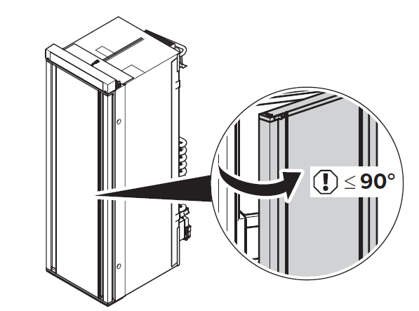
- To enable the refrigerant to circulate properly, the refrigerator may not exceed an angle of 3°.Park the vehicle horizontally for this purpose.
- The refrigerator must be installed so that– it is easily accessible for service work– easy to de-install and install– can be easily removed from the vehicle
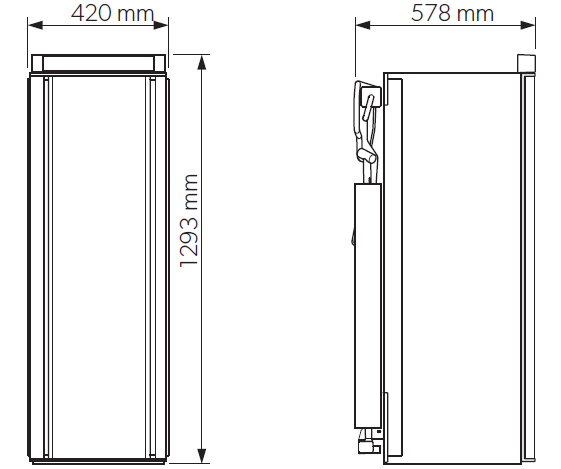
- The refrigerator must be installed in a recess so that it stands firm when the vehicle is in motion. Note the dimensions in fig. 1, page 3 for this purpose.
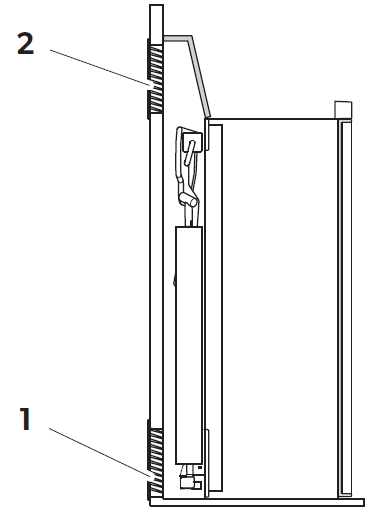
- The outer wall must be fitted with an air inlet vent (fig. 2 1, page 3) and an outlet vent (fig. 2 2, page 3) with ventilation grills so that the heat generated can be easily released to the outside:– Air inlet vent: Fit ventilation grill as flush as possible with the base of the installation niche.– Outlet vent: fit as far above the refrigerator as possible.– The distance between the air inlet and outlet vents must be at least 1050 mm (fig. 3, page 4).
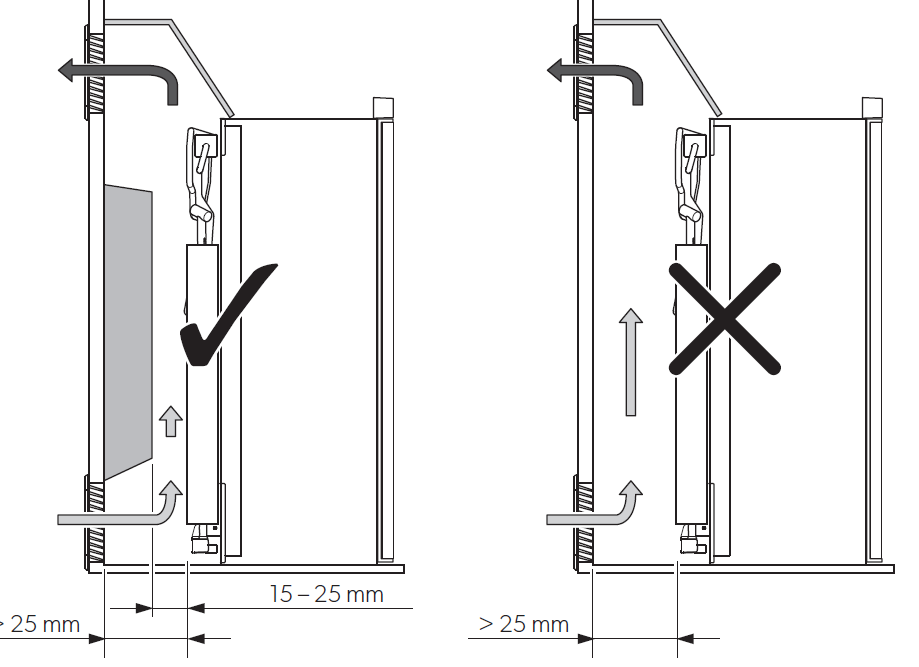
- Fit a heat conduction plate (fig. 3 1, page 4) above the refrigerator so that the heat does not accumulate in the vehicle.
- The distance between the refrigerator and the rear wall must be at least 15 mm but no more than 25 mm.
- A distance of more than 25 mm between the refrigerator and rear wall leads to poor performance and increases the power consumption of the refrigerator. Reduce the space behind the refrigerator to create adequate air inlet and outlet ventilation (fig. 4, page 4). Use a ventilation plate, for example, to do this.
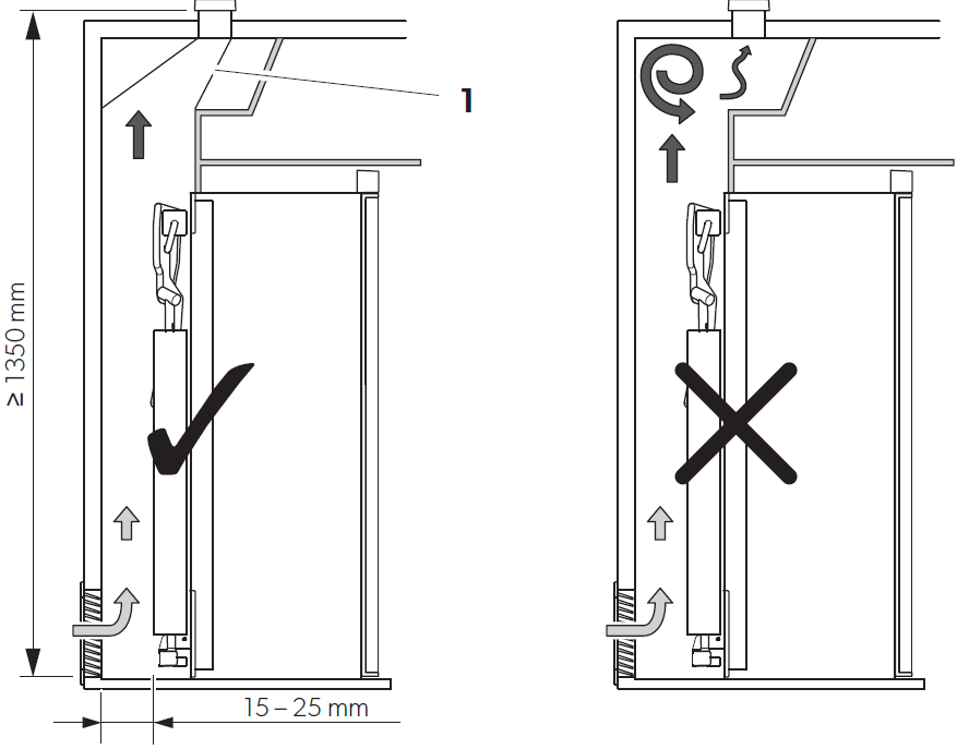
- If the minimum distance between the air inlet and outlet vents cannot be met, a roof vent must be installed instead of the air outlet vent.– The roof vent should be installed directly above the back of the refrigerator as far as this is possible. Use an air duct (fig. 5 1, page 5) if you need to install the roof vent offset; otherwise, heat will accumulate there.– The distance between the air inlet vent and the roof vent must be at least 1350 mm (fig. 5, page 5).– If a roof air conditioner is provided, the distance between the roof vent(fig. 6 1, page 5) and the air outlet of the roof air conditioner (fig. 6 2, page 5) must be at least 300 mm.
- The refrigerator must not be installed at the side of the air inlet and outlet vents as this leads to poor performance and increases the power consumption of the refrigerator.
- The air inlet and outlet vents must not be covered by vehicle parts (such as an open door or by installing accessories such as bicycle racks) while operating.
- Install the refrigerator so that it is protected from excessive heat, as this leads to poor performance and increases the power consumption of the refrigerator.
- The refrigerator must be installed in a draft-proof location.
 – Air inlet vent: Fit ventilation grill as flush as possible with the base of the installation niche.– Outlet vent: fit as far above the refrigerator as possible.– The distance between the air inlet and outlet vents must be at least 1050 mm (fig. 3, page 4).
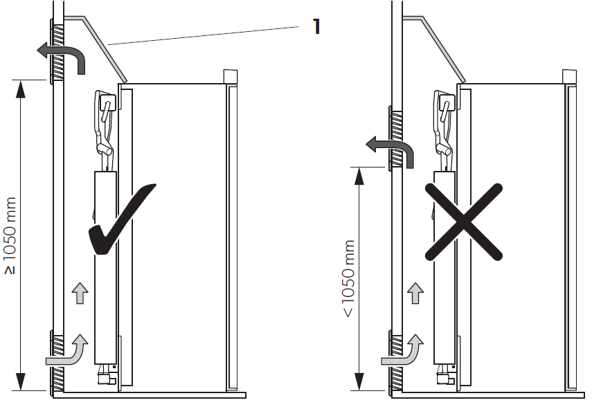
 – If a roof air conditioner is provided, the distance between the roof vent(fig. 6 1, page 5) and the air outlet of the roof air conditioner (fig. 6 2, page 5) must be at least 300 mm.
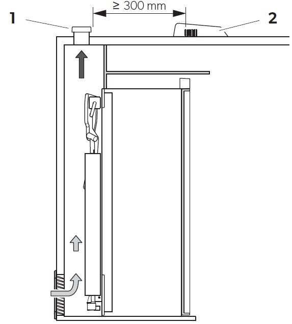
Installing the refrigerator in a draft-proof location
WARNING! Fire hazard!
- Do not use flammable materials such as silicone sealants, foam or similar for the draft-proof installation.
- Position the device so that no connection cable is damaged or pinched.
- Do not use multiple sockets or portable power adapters behind the device.
Gas-powered refrigerators in camper vans or mobile homes must be installed in a draft-free location. This means that the combustion air is not extracted from the inte-rior and the exhaust fumes are prevented from directly entering the living space.A suitable seal must be fitted between the rear panel of the refrigerator and the interior of the vehicle.
The manufacturer recommends using a flexible seal to ease removal and installation for maintenance purposes.Select one of the three versions for draft-proof installation (fig. 7, page 6):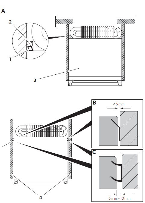
Stop bar behind the fridge (A)
- Glue a flexible sealing lip (1) to a stop bar (2) behind the refrigerator (3).
- Push the refrigerator-oven combination against the stop bar with the flexible sealing lips.
- The space behind the refrigerator is sealed to the interior of the vehicle.
Side gap distance of up to 5 mm between refrigerator and furniture (B)
- Glue the sealing lips (see chapter “Accessories” on page 13) on the side of the furniture (4).
- Push the refrigerator-oven combination against the flexible sealing lips on furniture.
- The space behind the refrigerator is sealed to the interior of the vehicle.
Side gap distance of 5 mm to 10 mm between refrigerator and furniture (C)
- Glue the double lipped sealing (see chapter “Accessories” on page 13) on the side of the furniture (4).
- Push the refrigerator-oven combination against the double lipped sealing on furniture.
- The space behind the refrigerator is sealed to the interior of the vehicle.
Making air inlet and outlet vents
- Deviations from the inlet and outlet variations shown here must be approved by the manufacturer.
- At high ambient temperatures, the refrigerator can only provide its maximum cooling capacity if the optimum ventilation has been pro-vided.
- Make an air inlet vent and an air outlet vent in the outer wall with the size of– LS230: 315 mm x 373 mm– LS330: 249mm x 410mmWhen doing so, observe the information, see chapter “Preparing the installation” on page 15.
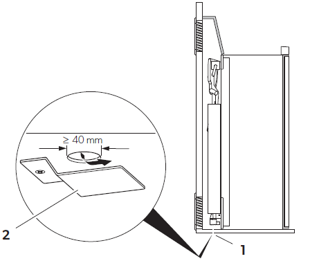
If the ventilation grill of the air inlet vent cannot be installed flush with the floor of the niche, install an inlet vent in the floor. Any leaking gas can thus flow downwards.
- Make an air inlet vent of at least Ø 40 mm in the floor (fig. 8 1, page 7) behind the refrigerator near the gas burner.
- Shield the outside of the opening with a deflector to prevent sludge or dirt from getting inside while driving (fig. 8 2, page 7).
If you have to use a roof vent instead of the air outlet vent:
- Cut out a section in the roof. Refer to the roof vent instruction manual for the required dimensions.When doing so, observe the information in chapter “Preparing the installation” on page 15.
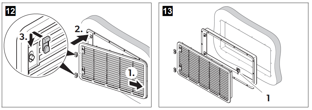
Installing the ventilation grill
NOTE Use exclusively original Dometic ventilation grills to ensure safe operation. 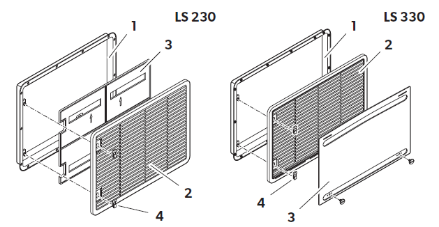
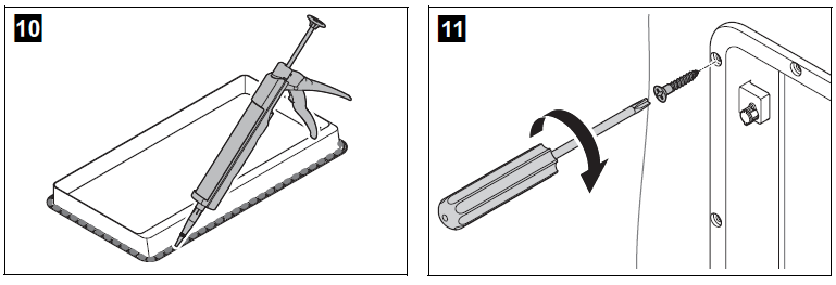
- Seal the installation frame to make the connection waterproof (fig. 0, page 7).
- Insert the installation frame and screw it down tightly (fig. a, page 7). Use all the fixing holes for this.
- Insert the ventilation grill as shown (fig. b, page 8).
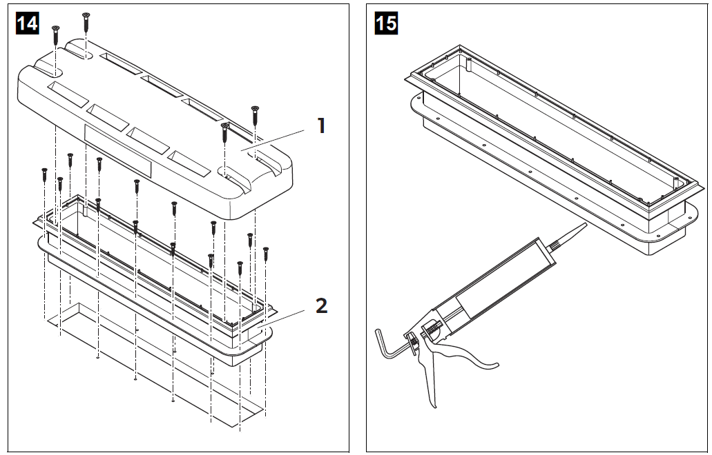
Installing condensation drain
- Condensation can form inside the refrigerator due to frequent door opening, incorrectly stored food or food that is stored when it is too warm.
- Condensation must be drained with a constant slope.
Install the condensation drain as follows:Variant 1 : Run the condensation hose from the refrigerator through an opening in the floor which goes outside under the vehicle.
Variant 2: Attach the condensation hose directly to the fitting intended for it on the ventilation grill (fig. c 1, page 8).Install the roof vent
 Install the roof vent
- Seal the installation frame to make the connection waterproof (fig. e, page 8).
- Insert the installation frame and screw it down tightly (fig. f, page 8). Use all the fixing holes for this.
- Insert the hood and screw it down tightly (fig. g, page 8).
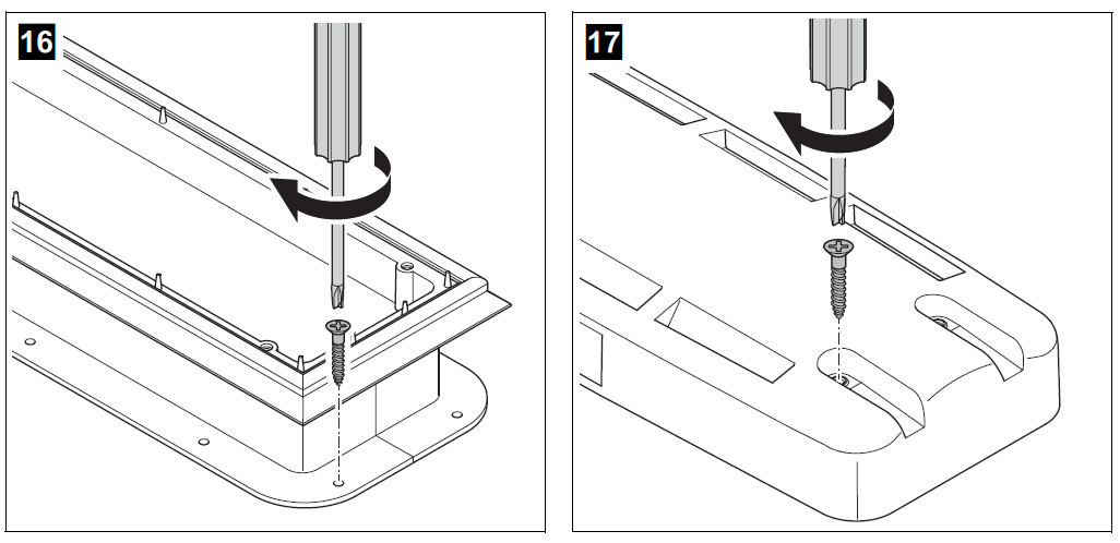
Securing the refrigerator
CAUTION!Only screw through the receptacles provided, otherwise foamed components, such as cables, can be damaged.
NOTEAttach the side walls or the attached strips so that the screws are tight, even when under increased loads (while driving).
- Move the refrigerator into its final location.
- Fasten the six screws (fig. h 1, page 9) through the six plastic washers in the sides of the refrigerator, and further into the wall.
- Put the caps (fig. h 2, page 9) onto the screw heads.
Connecting the refrigerator
Connecting to the gas supply
NOTICE!
- This refrigerator may only be connected to the gas supply by a specialist in accordance with the applicable guidelines and standards.
- A hose connection is not permitted.
- Use a metal-sealed screw connection.
- The gas filter (white) in the refrigerator gas connection must not be removed.
- Only use cylinders of propane or butane gas (not natural gas or city gas) with an approved pressure reduction valve and suitable head. Compare the pressure information on the type plate with the pressure information on the pressure regulator on the propane or butane gas cylinder.
- Only operate the refrigerator at the pressure shown on the type plate.
- Only operate the refrigerator with the type of gas shown on the type plate.
- Please note the pressures which are permitted in your country. Only use pressure controllers with a fixed setting which comply with the national regulations.
NOTE: Optionally, you can use the Dometic flexible gas connection pipe to keep the installation tensionless.
It must be possible to shut off the refrigerator from the gas line separately by means of a shut-off device. The shut-off device must be easily accessible.
- Connect the refrigerator securely by hand to the gas supply (fig. i, page 9): Please note the following information:
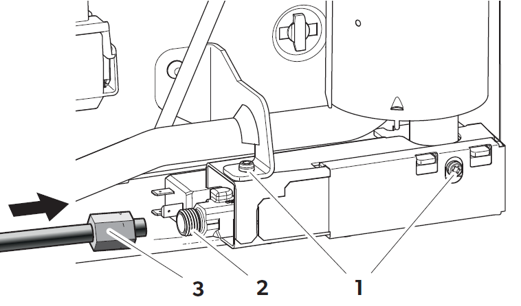
- Screw M4 (Torx TX20), Tightening torque: 2 Nm
- Refrigerator gas connection:M14 x 1.5 (d = 8 mm/ISO8434 (DIN2353))
- Gas pipe with ring coupling (size 17), Tightening torque: 25 Nm
Have a leak test and a flame test performed by an authorized specialist after professional installation.Ensure you are issued with a certificate of inspection and hand this certificate to the end user for safekeeping.
Connecting to DC and AC
NOTICE!The electrical installation and repairs may only be performed by a specialist in accordance with the applicable regulations and standards.
- The device plug must not be placed directly behind the ventilation grill in order to prevent the air circulation from being impaired and to protect the device plug from splashes of water.
- The device plug of the AC connection cable must not be cut off.
- The connection cables must be laid so that they do not come in con-tact with hot parts of the unit/burner or with sharp edges.
- Changes to the internal electrical installation or the connection of other electrical components (e.g. extra third party fans) to the internal wiring of the refrigerator will void any claims from the guarantee and product liability.
- The refrigerators RML10.4 and RML10.4T have a CI bus interface and can be controlled through a compatible central vehicle display.
Circuit diagram of the refrigerator
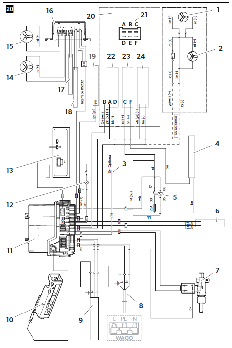
- Fan 2 (if options module is not available)
- Fan 1 (if options module is not available)
- S+ (optional)
- Heating element DC
- DC relay with 20 A fuse for heating cartridge
- NTC 1: Refrigeration roomNTC 2: Outside temperature (optional)
- Gas valve
- AC power supply
- Heating element AC
- Gas burner
- Connection block
- Lightning
- Display
- Fan 2 (if options module is available)
- Fan 1 (if options module is available)
- Options module
- DC supply oven (if options module is available)
- DC supply options module
- CI-Bus connection
- DC supply cable
- 12 V terminal housing (front view)
- AMP/TE Tyco: 180906
- CS Colombo: 63N025
- DC supply cable electronics
- DC supply cable heating element
- internal DC supply, max. 1 A (options module, oven, fan)
Connecting the refrigerator
DC power
- The supply line to the heating element must be protected with a 20 A fuse.
- The supply line to the electronics must be protected with a 2 A fuse.
- NOTICE!The respective positive and negative supply lines of the DC connections for electronics and heating element may not be joined with one another and carried on a single wire. This can cause electrical interference or damage to electrical components.
Please note the following cable sizes:
- < 6 m (in the interior): at least 6 mm2
- > 6 m (in the interior): at least 10 mm2
- Connections electronics and heating element: 0.75 mm2
- Connections D+ and S+: 0.75 mm2
- Cable fed via drawbar (caravans only): 2.5 mm2
- Assemble your DC socket as follows (fig. j, page 10):– Connect A and C to the positive pole of the battery.– Connect D and F to Connect D and F to ground.– Connect B to the D+ signal.
The electronics of the refrigerator uses the signal D+ from the light system to detect the running engine. In automatic mode, the refrigerator selects the most favorable mode available. The refrigerator is only operated with direct current when the vehicle engine is running.
- Connect E to the CI-BUS.
- Connect 3 with the S+ signal (optional).
- Protect the supply line A with a 2 A fuse in the power distribution box of the vehicle.
- Protect the supply line C with a 20 A fuse in the power distribution box of the vehicle.
Run the supply line C via an ignition-controlled relay. This prevents the battery from completely discharging if the engine is switched off accidentally.
Disposal
NOTEThis device contains flammable insulation blowing gas.Only have the device removed and disposed of by a specialist.
Protect the environment!Do not dispose of any batteries with general household waste. Return defective or used batteries to your retailer or dispose of them at collection points.
Technical data
| RML10.4 | RML10.4S | RML10.4T | |
| Connection voltage: | 230 Vw/50 Hz
12 Vg |
||
| Capacity | |||
| Gross capacity: Refrigerator compartment:
Freezer compartment: Total net capacity: |
133 l
116 l 12 l 128 l |
||
| Excluding freezer compartment | |||
| Gross capacity: Net capacity: | 139 l
134 l |
||
| Power consumption: | 170 W (230 Vw)
170 W (12 Vg) |
||
| Energy consumption: | 3.2 kWh/24 h (230 Vw)
340 Ah/24 h (12 Vg) |
||
| Gas consumption: | 380 g/24 h | ||
| Gas connecting pressure: | 30 mbar | ||
| Climate class: | SN | ||
| Dimensions H x W x D: | 1293 x 420 x 578 mm |
| RML10.4 | RML10.4S | RML10.4T | |
| Weight: | 35 kg | 32 kg | 35.5 kg |
| Inspection/certification: | 1 |
For the current EU Declaration of Conformity for your device, please refer to the respective product page on dometic.com or contact the manufacturer directly (see back page).
![]()
References
[xyz-ips snippet=”download-snippet”]