Installation Manual

New Dometic SZLCD
WHAT YOU MUST KNOW:
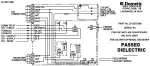
The Dometic Single Zone Liquid Crystal Display(SZLCD) PN’s 3313189.XXX are not backwards compatible. Therefore you cannot use the SZLCD thermostat with the old analog relay board and you cannot use the SZLCD control relay board with the analog thermostat. However, you do not have to replace the 7 conductor cable for the low voltage connections if you already have this installed in the ceiling or walls.
Here are the 2 ways to connect 12VDC to your new DOMETIC SZLCD control:
Low Voltage 12VDC control wires:
1. INSTALLED WITH THE A NEW 3 CONDUCTOR COMMUNICATIONS CABLE: (normally a new installation)
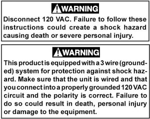
- Route a dedicated 12VDC supply wire (18-22 AWG) from the RV’s converter (filtered side) or the 12VDC battery to the 14 ¼’ x 14 ¼” opening. This supply wire must be located in the front portion of the opening. Make sure that at least 15” of supply wire extend into the roof opening.Disconnect the positive (+) 12 VDC terminal at the supply battery. Damage to equipment could occur if the 12 VDC is not shut off.
- Wire fish and Route the new 3 conductor cable, (18-22AWG) through the wall or ceiling from the opening on the wall for the thermostat mounting, into the 14 ¼” x 14 ¼” opening in the ceiling. Make sure that there is at least 15” of this 3 conductor wire extending into the opening in the ceiling for the air distribution box and 6” extending into the hole where the thermostat mounts on the wall.
- For the 3 conductor communications cable installation the wire colors or the cable match the wire colors in the harness at the SZLCD control box. Available wire colors in the cable may vary. (The key is to match the colors to the connections at both ends)
- Remove the cover from the SZLCD thermostat. Depress tab on bottom of thermostat and separate it from the base.
- Insert the previously run three (3) conductor cable through the hole in the base assembly.
- Cut back the outer cable shield approximately 3 inches and strip 1/4″ insulation from each wire.
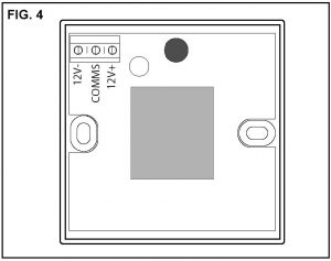
- Mount the thermostat level on the wall using the screws provided. Make the following connections to the thermostat. See FIG 4. • Red/white wire to the 12V+ terminal• Black wire to the 12V– terminal• Orange wire to the “COMMS” terminal.

- Inspect all connections to make sure they are tight and not touching any other terminals or wires.
- Push the wires back through the base into the wall. Place cover on the thermostat and push until an audible click is heard.
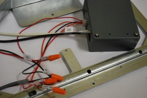
- At the 14 ¼” x 14 ¼’ opening, connect the following:• Plug the supplied four conductor wire harness that is red/white, orange, black, and red into the SZLCD control relay box.• Connect the +12VDC red supply wire to the red wire from the SZLCD control relay box.• Connect the -12VDC black supply wire to both the black wire from the SZLCD control relay box and the black wire from the SZLCD -12VDC terminal running from the thermostat.• Connect the red/white wire from the SZLCD thermostat +12VDC terminal to the red/ white wire from the SZLCD control relay box.• Connect the orange wire from the SZLCD thermostat COMMS terminal to the orange wire that runs from the SZLCD control relay box.
2. REQUIRED CONNECTIONS WHEN YOU ARE USING THE EXISTING 7 WIRE CONTROL CABLE ALREADY INSTALLED IN THE WALLS OR CEILING OF THE VEHICLE.
- Route a dedicated 12VDC supply wire (18-22 AWG) from the RV’s converter (filtered side) or the 12VDC battery to the 14 ¼’ x 14 ¼” opening. This supply wire must be located in the front portion of the opening. Make sure that at least 15” of supply wire extend into the roof opening. The +12VDC wire should be red and the -12VDC wire should be black.
- Make sure that there is 6” of 7 conductor cable extending through the wall at the location for the wall thermostat.
- Make sure that there is 10-15” of the 7 conductor cable extends into the 14 ¼” x 14 ¼” opening at the ceiling
- Locate your new SZLCD thermostat and remove the cover. Depress tab on bottom of thermostat and separate it from the base.
- Insert the previously run seven (7) conductor cable through the hole in the base assembly. (These colors may vary. The key
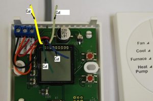
- Cut back the outer cable shield approximately 3 inches and strip 1/4″ insulation from the red/white, black, and the orange wires so that the copper conductors are exposed.
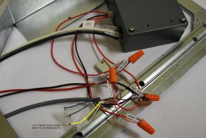
- Using a pair of side cutters, simply cut the, yellow, tan, blue, and green wires back to the outer sheath on the 7 wire cable.
- Please tape the ends of these wires with black electricians tape.
- Mount the thermostat level on the wall using the screws provided. Make the following connections to the thermostat. See FIG 4.
- Connect the 12VDC+ or red/white wire to the 12VDC+ terminal on the SZLCD thermostat.
- Connect the 12VDC- or black supply line to the 12VDC- terminal on the SZLCD.
- Connect the orange wire of the cable to the “Comms” terminal on the SZLCD.

- At the other end of the cable in the 14 ¼” x 14 ¼” opening connect the following:
- Plug the supplied four conductor wire harness that is red/white, orange, black, and red into the SZLCD control relay box.
- Connect the +12VDC red supply wire to the red wire from the SZLCD control relay box.
- Connect the -12VDC black supply wire to both the black wire from the SZLCD control relay box and the black wire routed from the SZLCD -12VDC thermostat terminal.
- Cut back the outer cable shield from the seven (7) conductor cable approximately 3 inches and strip 1/4″ insulation from the red, black, and the orange wires so that the copper conductors are exposed.
- Using a pair of side cutters, simply cut the, yellow, tan, blue, and green wires back to the sheath on the 7 wire cable.
- Please tape the ends of these wires with black electricians tape.
- Connect the red/white wire routed from the SZLCD thermostat +12VDC terminal to the red/white wire from the SZLCD control relay box.
- Connect the orange wire from the SZLCD thermostat COMMS terminal to the orange wire that runs from the SZLCD control relay box.
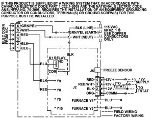
IF YOUR SYSTEM INCLUDES A GAS FURNACE, THE WIRING WILL BE SEPARATE FROM THE 3 OR 7 CONDUCTOR CABLE. THEREFORE IN EITHER CASE FOLLOW THESE STEPS.
- Route two 18 gauge thermostat wires from the furnace to the roof opening of the unit that will control it. If more than one furnace is to be used, route the second set of two (2) thermostat wires to the second unit. Make sure that 15″ of wire extends into the opening.
- Plug the 2 blue wires that are provided into the their matching connectors on the SZLCD control relay box.
- Connect the two wires routed from the furnace to the 14 ¼” x 14 ¼” opening of a. above to the blue wires that you have just plugged into the control relay box.
CONNECTING 120V AC TO THE SZLCD CONTROL RELAY BOX WHETHER YOU HAVE A SEVEN (7) OR (3) WIRE THERMOSTAT CABLE IS AS FOLLOWS.
Wiring Requirements
1. Route a copper, with ground, 120 VAC supply wire from the time delay fuse or circuit breakerbox to the roof opening. The proper size wire can be determined from the chart on page 3 of your installation manual.
- This supply wire must be located in the front portion of the 14-1/4″ x 14-1/4″ (±1/8″) opening.
- The power MUST be on an appropriately sized separate time delay fuse or circuit breaker. The proper size protection can be determined from the chart on page 3.
- Make sure that at least 15″ of supply wire extends into the roof opening. This insures aneasy connection at the junction box.
- Wiring must comply with the National Electrical Code ANSI/NFPA-70 and CSA StandardC22.1 (latest edition) and any State or Local Codes or regulations.
- Protect the wire where it passes into the opening with approved method. See paragraph “d” above.
- Route the 120 VAC supply wire through the strain relief in the SZLCD control box. Tightenstrain relief, making sure enough wire is inside SZLCD control box to connect with unit 120VAC wires
- Connect the white to white; black to black; and green or bare copper wire using appropriate size wire connectors. See chart on page 3 of your installation manual.
- Push the wires into the SZLCD control box and install the cover with the four blunt pointscrews provided.
New Dometic SZLCD Installation Manual – New Dometic SZLCD Installation Manual –
Questions about your Manual? Post in the comments!
[xyz-ips snippet=”download-snippet”]