


advanced hotel management

Technical guide for the realization, installation and configuration of the Network System.
Version 1.0 rev01 May 2012
TABLE OF CONTENTS
4. BUILDING WORKS (construction sites) 4
4.1 Flush mounting boxes for devices 4
4.2 Flush distribution boxes for room control units 5
4.3 Plastic flexible conduits 5
5. automation plant realization 5
5.1.3 Wiring of “occupied Room” and “open Window” function on thermostats 7
5.4 Connecting the programmer SCR-ALBM1 10
6.1 Gateway or Ethernet interface cod. AR-NET01 11
6.2 Room control unit cod. 53AR01-485 and common area unit cod. 53AR02-485 12
6.3 Outdoor reader (access to the room) 44..GA01-M or 442GA02 M 13
6.3.1 Access mode configuration 13
6.4 Indoor reader (presence detector) 44..GA30-M 14
6.4.1 Access mode configuration 14
6.5 Room thermostat 44..GA52-T 15
6.6 Home automation devices 15
7.1 Requirements and limitations 17
7.3 Activation of the user software license 19
8. PLANT software configuration 20
8.1 Start-up of the application DHSys Client 20
8.2 Access to the system configuration 21
8.3 System parameters setting 21
8.4 Programmer SCR-ALBM01 – parameters setting 22
8.5 Maintenance of the system (plant configurator) 22
9.1 Preventive Super Guest cards creation 49
10. devices for network hotel management 50
10.1 Room control unit art. 53AR01-485 50
10.2 Common areas control unit cod. 53AR02-485 53
10.3 Outdoor transponder readers art. 44…GA01-M o 442GA02-M (Touch) 56
10.4 Indoor Transponder Readers art. 44..GA30-M 58
10.5 Room Thermostat art. 44…GA52-T 60
12. wiring diagrams AND schemes 65
12.1 Inputs wiring diagram to the room control unit 53AR01-485 65
12.2 Thermostat wiring diagram 44..GA52-T 66
12.3 Room relay wiring diagram 66
12.4 “Diagram example” for connection of a plant 68
This guide has the purpose to instruct the installer to the wiring realization of a hotel automation system and to the related configuration of the essential parameters needed to its correct working.
In the next pages of this document, all the necessary precautions and instructions will be given for the optimal realization of the plant: starting from the constrains of the building works, through the practical wiring, up to the illustration of all aspects of the software, therefore allowing the realization of a complete hotel management system with optimal performances.
The hotel management system of AVE (Domina Hotel) has been designed, tested and approved to comply to the current European Rules and Regulations as regards the realization of electric wiring systems. Besides the respect of the standards in force, all the electric wiring arrangements must be respected, starting from suggestions for the realization of the building works until the information about the configuration of the system, that will be described in the following paragraphs.
For the correct realization of a network hotel management plant, it is important to consult the standards for electrical installations in building, such as:
BS 7671 , the 17th Edition of the IEE Wiring Regulations and Building Regulations.
(note: you should be aware that this guide does not ensure compliance with the Building Regulations of your Country; you shall always consult the relevant regulations to ensure
compliance).
A correct positioning of the electrical devices and equipment during the building works, such as the placement of the flush mounting boxes and the plastic flexible conduits, simplifies and accelerates the subsequent operations of wiring and installation of the plant. It is strongly recommended and necessary to follow all the described installation rules as described below:
The flush mounting boxes for the accommodation of the devices must be installed in the wall so that the resultant useful internal depth for the devices housing is as much as possible: this will make the following wiring operations easier. It is strongly recommended the use of rectangular boxes AVE code 2503MG for concrete walls and 253CG for hollow walls, (83.5 mm screw fixing centres).
Transponder card readers
The flush mounting boxes suitable for these devices must be typically placed to a 110 cm height from the floor, and plastic flexible conduits must come in sideward on the box bottom.
Room thermostats
The flush mounting boxes suitable for these devices, must be typically placed to a 150 cm height from the floor, and plastic flexible conduits both for the bus cabling and for the electrical loads must come in sideward on the box bottom. For the positioning of these boxes, with the aim to guarantee a correct detection of the environment temperature of the thermostat, some precautions must be respected and, in particular, the boxes for the thermostats must never be positioned:
- On the outer walls
- In front of windows/transparent doors or in direct solar radiation areas
- Next to and/or in front of fan-coils, radiators, water heaters
- Close to heating pipes and/or air-conditioning pipes or on walls that could be heated
Home automation devices
The flush mounting boxes suitable for these devices can be installed to different height from the floor according to the features of the device, and the plastic flexible conduits must come in sideward on the box bottom.
The transmitters are typically placed to 110 cm height from the floor, while the actuators can be placed to 40 cm height from the floor as usual for the socket-outlets.
Anyway to solve some installation requirements these devices can be installed also into DIN distribution boards by means of suitable adaptors:
-cod. 53/44/1 for 1 module devices,
-cod. 53/44/2 for 2 module devices.
The flush distribution boxes provided for the housing of the control units must be of such dimensions as to ensure the installation of a consumer unit of 12 DIN modules (minimum), placed in an area that can be later inspected.
A separation between the bus cables (SELV) and main supply to the loads (LV) must always be guaranteed.
Also the common area control units can be installed inside cabinets or consumer units that, anyway, can be later inspected.
Also in the case of installation in consumer units, a separation between the bus cables (SELV) and the main supply lines (LV) must be guaranteed. A right dimensioning of the box has to be done so that a correct ventilation of the room control unit can be guaranteed. Too tight and narrow spaces and the presence of amassed electric wires can cause an overheating of the device with failures of the plant as a consequence. It is also recommended to install these boxes far from heat sources and/or from the water pipes.
To make a correct hotel automation wiring installation, must be foreseen connections between the flush mounting boxes using flexible conduits of such dimension to allow an easy passing of the cables. The flexible conduits for the bus cables (SELV) must be separated from the main supply lines (LV) keeping the clearances specified by the current regulations. It is also recommended the use of flexible conduits of different colours between SELV and LV so that it can be possible to identify them immediately.
The respect of the standards in the realization of electric wiring installations, such as separation between SELV and LV lines and/or correct realization of the communication lines, reduces testing and inspection time and reduces the possibilities of failure of the system, thus it is strongly necessary to follow all the installation rules outlined below in the following paragraphs.
 For plant installations made not in according to what above described, AVE S.p.A. declines any responsibility for possible failures that may occur on the hotel management system. AVE S.p.A. reserves also the right not to provide assistance on installations that are not realized accordingly to what was listed above or not in conformity with the current standards and regulations
The electric wiring installation must be realized in conformity with the current standards and moreover all the main supply cables (LV) must go through the suitable flexible conduits and must not share the flexible conduits with the SELV lines (communication bus).
All the minimum cable sections required by the supply of the loads and the maximum ratings of the different automation device outputs must be respected. If a load output does not have the suitable requirements (max rated current and/or max applicable voltage), it is necessary to interpose a relay of support with suitable ratings.
Make the connection to the devices, signals of communication (SELV) and of supply of the loads (LV), so that they also stay isolated even after the accommodation of the devices in the box, to avoid as much as possible any interference to the communication bus lines that could be caused by on-off commutation of the loads. This is the reason why it is advisable that the cables for the supply of the loads inside of the boxes (in which devices are placed) do not turn out to be too long.
To use at the best the automation system in every condition (door lock opening, alarms and temperatures detection), in case of power failure, it is strongly suggested to provide and use a back-up power feeding such as UPS device to enable the processes to continue, including the activity of the supervisor PC on which the communication server is installed. This suggestion is important to minimize damages to the devices due to environmental events (storms and flashings) or to working condition events (fast transient, voltage dips, short interruptions).

The dimensioning of the back-up power feeding unit has to take into account the number of the devices connected (including the supervisor PC) and their medium consumption of current.
The network hotel management room control units (rooms: cod. 53AR01-485 and/or common areas: cod. 53AR02-485) and the access readers (outdoor card reader cod. 44._GA01-M or 442GA02 M) are equipped with an output to manage the electro door lock used to open the door.
This output is a potential-free contact (dry contact pin 11-12 of the connector placed in the lower side of the room control unit) which is closed for the pre-set time at recognition of a valid card on the outdoor reader.
The closing time of the contact is programmable via software with variable time between 0,1 and 25 seconds so that it is possible to manage electro door locks with or without spring pivot.
Devices with spring pivot allow to use a short (typically included between 0,3” and 0,8″) impulse to open the door that will remain unlocked until it will not be opened and closed again. The devices without spring pivot use instead longer activation time (typically from 3” to 8″) as they only keep the door unlocked during the activation time. At the end of which the door is locked again.
To avoid any electromagnetic disturbances that could influence the release of the electro door lock, it is recommended to foresee a transformer (eg. AVE cod. 5347-12Vac) to be used only for the management of the electro door lock. To remove the annoying buzzing produced by electro door lock supplied in alternate current (or to manage electro door lock in direct current DC) it is necessary to interpose a “silencer” device between the output and the electro door lock (cod. GADS01).
For electro door locks supplied in direct current (DC) it is also possible to use, alternatively to the transformer with the “silencer”, a stabilized power feeder cod. 53ABAUX12V.
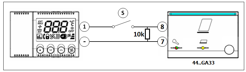
The wiring for the detection of the window status and, optionally, for the detection of occupied room, must be realized as shown in one of the figure below (Fig.1a Fig.1b.)
The figure 1a is the typical room wiring where the guest’s presence is detected by the indoor transponder reader cod. 44..GA30-M and, via ARMBus, communicated to the thermostat.
Although strongly discouraged because of the decay of available information for the room, it is possible to apply the configuration shown in figure 1b in case the room has, as presence device, a “key card switch” (Ave cod. 44..GA33 or others). In this case the status of occupied room is taken directly by the thermostat even if it is not possible to verify which type of card (guest, chambermaid or others) is inserted. How one can see from the scheme here under, to realize this configuration it is necessary to connect a resistor of 10kOhm / 0.25 W in parallel to the output terminals of the device key-card switch.
![]()
Fig. 1a Fig. 1b
The bus communication lines must be realized in conformity with the current standards and moreover all the cables reserved to the SELV lines (communication bus) must go through the suitable flexible conduits and must not share the flexible conduits related to the main supply lines (LV).
All the required features for the bus cable (see cod. CVAVEBUS) and the maximum length constraints for the bus communication line must be respected.
The cable to be used (cod. CVAVEBUS) is composed of two twisted shielded pairs of 0.5 mm2 (a total of 4 conductors).
The shield (or sleeve) of the CVAVEBUS (or equivalent one) must not be connected to ground of the plant but only to the (GND) terminal of the RCU connector from which starts the bus line.

Backbone communication line (NETBus)
The backbone communication bus, named NETBus, (bus line between room control units/common areas control units cod. 53AR01-485/53AR02-485 and gateway cod. AR-NET01), allows to realize a communication line of a maximum length equal to 1200 meters. To obtain these characteristics it is necessary to use the CVAVEBUS cable (or a cable with equivalent or better electrical features).
The communication bus must be realized adopting the multi-drop topology (in and out cabling). Any other installation topology (star, daisy-chain, loop, etc.) does not guarantee a correct communication between the devices and therefore IT IS NOT ALLOWED.
The connection between the devices and the backbone communication cable must be made by means of the green colour conductor for the line ![]() , the red colour conductor for the line
, the red colour conductor for the line ![]() and the two black colour conductors for the ground connection (GND).
and the two black colour conductors for the ground connection (GND).
The sleeve (shield) of the CVAVEBUS cable (or an equivalent one) must have electrical continuity over all the line and it must not be connected to the ground of the wiring installation but only to the terminal (GND) on the NETBus of the device AR-NET01.
One resistor (R=120Ω ½W provided in the packaging of the cod. AR-NET01) must be connected between the terminal ![]() and
and ![]() of the suitable terminals (blue colour – 3 poles) both at the beginning and at the end of the Netbus line.
of the suitable terminals (blue colour – 3 poles) both at the beginning and at the end of the Netbus line.
Bus communication line to room devices (ARMBus)
The communication bus with room devices, named ARMBus, is realized by means of a bus cable between room control units (cod. 53AR0x-485) and room devices (transponder readers and/or thermostats). Even if it is always recommended to realize the shortest possible wiring to minimize interferences, following the below specified cabling specifications, it is possible to make a communication line of a maximum length of 100 meters using the cable CVAVEBUS (or a cable with equivalent or better electrical features).
The communication bus must be realized adopting the multi-drop topology (aka “in and out” cabling). Any other installation topology (star, daisy-chain, loop, etc.) does not guarantee a correct communication between the devices and therefore IT IS NOT ALLOWED.
The cabling to be used for the communication between room control unit and room devices must be made using the RED/BLACK pair for the power supply (RED positive/ BLACK negative) and the GREEN/BLACK pair for the bus communication (GREEN for line A and BLACK for line B) following the indications in the figure below.
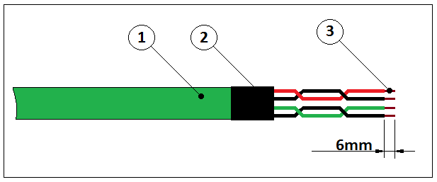
(1) bus cable cod. CVAVEBUS (2 “twisted” shielded pair of 0.5mm2)
(2) Thermo retractile sheath to insulate the shield when not used
(3) Strip off the single wires to 6mm for a correct connection in the terminal boards
The sleeve (or shield) of the CVAVEBUS cable (or an equivalent one) must have electric continuity over all the line and it must not be connected to the earth of the system but only to the terminal (GND) on the ARMBus connector of the room control unit. It must also be duly isolated correctly to avoid contact with the screws of the terminals of the devices and it must not loop around the devices.
IT IS STRICTLY FORBIDDEN to wire the terminal blocks when mounted on the devices. They must be removed and put back in place only after the clamping of the conductors in order to avoid damages to the connectors themselves. On every room device (transponder card reader and/or room thermostat) must be subsequently placed into position the small lid (terminals lock) for the +12V and Bus connectors with the purpose to avoid any undesired contact.
Bus communication line to home automation devices (AVEBus)
The bus communication line with home automation devices, named AVEBus, (bus between room/common area control units – art. 53AR0x-485 – and home automation devices such as 441ABR1), allows to realize a communication line up to 100 meters length.
To obtain these characteristics it is necessary to use the cable CVAVEBUS (or a cable with equivalent or better electrical features).
The bus communication line can be realized adopting all the installation topologies allowed by the standards: the multi-drop topology (in and out cabling) is admitted as well as the others: star, daisy-chain, loop, etc.
The cabling to be used for the communication between the control unit and the home automation devices must be made using the red/black pair for the auxiliary supply (red positive/ black negative) and the green/black couple for the bus communication (green positive and black negative).
 It is strongly forbidden to use the 12V dc of the room control unit (ARMbus terminals) as well as of the same supply of the room control unit to feed the auxiliary line of the Avebus devices. A separate suitable stabilized power feeder (cod. 53ABAUX12V) must be used.
The sleeve (or shield) of the CVAVEBUS cable (or an equivalent one) is not required for this bus line and thus doesn’t need to be connected.
It is strictly forbidden to wire the terminal blocks when mounted on the devices. They must be removed and put back in place only after the clamping of the conductors in order to avoid damages to the terminals themselves. On every room device (e.g. AVE Domina codes 441ABR1 or 441ABRT01) must be subsequently placed into position the small lid (terminals lock) for the auxiliary supply and bus-line connectors to avoid any undesired contact.
The Ethernet line wiring must be made according to the standards and the regulations in force and by means of appropriate cables cat. 5E or superior.
All the requirements of the standards have to be respected such as cable to be used, maximum length of the lines, etc.
The gateway cod. AR-NET01 has been designed for the protocol 10/100 base-T with connector RJ45 standard. The Ethernet cable to be connected to the AR-NET01 must be placed into flexible conduits different from those used for the main supply and must allow the “physical” connection of the AR-NET01 to the internal network of the hotel plant.
 The interface between the automation system and the PC (Ethernet) is certified and has been tested on wired networks: it is not allowed a wireless connection nor partially neither complete) between the supervisor PC and the AR-NET01 device.
The programmer cod. SCR ALBM1 is a device that allows to read/write the transponder cards. It must be connected to the Client PC (computer placed in reception from which the cards will be prepared) through USB 2.0 cable supplied into the packaging with the device.
It is not allowed to use cables for the connection other than the one supplied in the packaging and cannot be extended if not by means of a certified HUB USB with its own independent supply.
The device is provided with an ARMBus jack which allows to configure the different devices of room (readers and thermostats) connecting them directly to this connector (through technical software SFW-ALBTEC). During the normal working of a network this jack connector is normally not used; for this reason must be protected so to avoid short circuits.
The programmer SCR-ALBM1 works in radio frequency and thus must not be installed in proximity of devices that could generate EM interferences (wireless routers, cordless telephones, etc.).
After executing with a preliminary control of the installation plant, verifying that all is realized according to the installation diagrams, proceed to the configuration of the different devices (Addressing, and/or logical functions). Following paragraphs illustrate the operations to be performed to set up the automation plant.
The device AR-NET01 is a connection interface between the backbone bus of the automation plant (NETBus) and the supervisor PC (Ethernet).
It is referable to a device of “gateway” kind that converts the data frames (UDP format) coming from the server of supervision in data packages to be sent to the plant and, vice versa, the answers and data coming from the plant in data frames for the supervision server.
Typically in a little-medium plant only one gateway AR-NET01 is installed even if it is possible install also more than one (the limit is given by the number of available IP addresses). Every gateway must have an univocal IP address on the LAN where it is connected to avoid conflicts with other devices on the net. For this reason, before setting up the IP address of the gateway, it is necessary to contact the network Administrator who will assign the IP address for AR-NET01. The IP address change and relative sub-parameters (subnet mask) must be performed through the technical software SFW-ALBTEC .

AVE S.p.A. supplies all the devices cod. AR-NET01 already set up with IP address: 192.168.1.168 and Subnet Mask 255.255.0.0. In case of use of only one gateway AR-NET01 and where allowed by the network settings it is possible to use it without modifying any parameter.
If on the same plant are installed more devices AR-NET01, these will certainly have to be re-addressed (IP) before being connected to the building network (through an hub/switch or router) where the supervisor PC will be also connected (see figure).
EXAMPLE OF CONNECTION WITH TWO AR-NET01
SUPERVISION PC
(IP: 192.168.1.1)
(MSK: 255.255.0.0)


AR-NET01 (1)
(IP: 192.168.1.168)
(MSK: 255.255.0.0)
AR-NET01 (2)
(IP: 192.168.1.169)
(MSK: 255.255.0.0)
SWITCH
(or Router)
After feeding the control units of room and/or common area, one must continue to the assignation of an address to communicate on the NETBus to every control unit of the plant that must be univocal for every control unit.
By default, all the control units are delivered from AVE with address (hexadecimal) NETBus 1.1.FE (shown on display at the third line as “Network Addr. X.Y.ZZ” where X=Area, Y=Line, ZZ=Device).
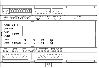
At the end of the boot procedure (flashing of all the LED on the front,) it is possible to modify the address of the control unit through the frontal keys and .
Before modifying the address check that the LED ![]() of the control unit blinks with red light. Otherwise the modification of the address is not possible as the control unit is currently polled by the supervisor PC.
of the control unit blinks with red light. Otherwise the modification of the address is not possible as the control unit is currently polled by the supervisor PC.
If LEDs are off (energy saving mode) it is possible to light them on for 1 minute pressing the key F4 on the front of the device. If the LED ![]() is on with red light blinking, begin the procedure directly from point 4, otherwise start from point 1.
is on with red light blinking, begin the procedure directly from point 4, otherwise start from point 1.
- Disconnect the connector NETBus (blue connector) from the control unit. This way the control unit of room/common area will no longer be polled by the supervisor and the procedure of address change can be enabled again.
- Turn off and on again the control unit to enabled again the procedure of address modification (without turning the control unit off, the procedure will be automatically reactivated after three minutes starting from when the connector was removed).
- Wait the end of the procedure of initialization of the control unit (lit of all the LED on the front)
- Using the frontal keys of increase () and decrease () modify the value of the parameter “Device” of the address NETBus until the desired value is reached ([1]). The management of the value “Device” is of circular type: pressing the key from the maximum value (FF) the next value to be displayed will be (00) and vice versa with the key . If it is necessary to modify the parameter “Area” and/or “Line” of the address NETBus, the operation has to be performed through the technical software SFW-ALBTEC ([2]) as the keys and modify only the parameter “Device”.
- If disconnected, connect the terminal block NETBus to the control unit.
It is recommended to connect the feeding of the control units under UPS.
The LCD display of every control unit shows the “Address” which is the unique identification of the node in the system.
The address must be given to the devices according to the configuration set in the supervising software.
Do not modify the addresses of the control units once the plant is fully configured to avoid conflicts with other rooms and to avoid inability of the software to poll the device.
Every maintenance action on the room control unit must be performed by skilled staff in respect of the instructions provided in this manual.
The access room reader is installed outdoor and allows its opening when a valid transponder card is recognized.
It is possible to manage up to two outdoor readers with a room control unit (53AR01-485) or four outdoor readers with a common area control unit (53AR02-485).
The configuration of the address of the device, where more than one reader is installed in a room or common area, must be performed through the software SFW-ALBTEC.
All the devices 44..GA01-M And 442GA02-M are provided with default setting: Address (0x10).
Room access reader
If the reader is connected to a room control unit the addressing must be done as follow:
- Address 0 (0x10): main reader to access the room
- Address 1 (0x11): secondary reader to access the room (typically used in the automation of Motel structure rooms).

To manage the access to the rooms, the outdoor reader must be configured in operating mode: ROOM READER (default configuration) through the card MASTER or by means of the technical software SFW-ALBTEC (see below).
Common area access reader
If the reader is connected to a common areas control unit, the addressing must be done as follows:
- Address 0 (0x10): Card reader to access the first area
- Address 1 (0x11): Card reader to access the second area
- Address 2 (0x12): Card reader to access the third area
- Address 3 (0x13): Card reader to access the fourth area
 To manage the access to the common areas, the outdoor reader can be configured in mode COMMON AREA READER, PREPAID ACCESS READER (possible access both for guests and service staff) or FACILITY ROOM READER (access for the service personnel ONLY) through the CARD MASTER or by means of the technical software SFW-ALBTEC (see below).
Through the card MASTER of the plant it is possible to set the desired access mode for the outdoor reader and to choose between the below listed modes:
- ROOM CARD READER: it allows the access to all the valid (not expired) guest card having the same plant code and the same univocal code associated to the reader (room number). To this room can also access, under certain conditions, all valid (not expired) service cards with the same plant code and enabled for the zone to which the room belongs.
- FACILITY ROOM CARD READER: it allows the access to all the valid (not expired) cards having the same hotel code that have parameters suitable to access the room. To this kind of room the guest cards and super-guest cards cannot access.
- COMMON AREA CARD READER: it allows the access to all the valid (not expired) cards having the same hotel code that have parameters suitable to access the room. To this kind of room the guest cards and super-guest cards can access when authorised.
- PREPAID ACCESS CARD READER: it allows the access to all the valid (not expired) cards (guest and service staff) having the same Hotel code with suitable parameters to access the room and that have a sufficient residual credit (once read, the card credit, will be decreased by one credit unit directly from the reader)
All the devices 44..GA01-M and 442GA02-M are provided with default setting: ROOM READER.
The instructions for the configuration of the operating mode of the outdoor reader through MASTER card, are reported on the stand alone system configuration manual available for download on AVE website.
The presence detector is installed inside the room and typically in an area near by the entrance and easily detectable. It allows the detection of the presence in the room through the recognition of a valid transponder card.
It is possible to manage up to four indoor readers with a control unit for common area (53AR02-485). While for the rooms (53AR01-485) it is possible to connect only one device with the default address (Do not change the default address when used in a room).
The configuration of the address of the device, in case of several readers present in the same common area, must be performed through the technical software SFW-ALBTEC.All the devices 44..GA30-M are provided with default setting: address (0x20).
Room readers
If the reader is connected to a room control unit the address is fixed and it should not be modified.
Common area readers
If the reader is connected to a control unit of common area, the addressing must be done as follows:
- Address 0 (0x20:) Presence reader in the first area.
- Address 1 (0x21): Presence reader in the second area.
- Address 2 (0x22): Presence reader in the third area.
- Address 3 (0x23): Presence reader in the fourth area.
 For the management of the presences in the common areas the indoor reader can be configured in mode COMMON AREA READER, PREPAID ACCESSES READER (access possible for guests and service staff) or FACILITY ROOM READER (access reserved to the personnel of service) through the MASTER card or through the technical software SFW-ALBTEC (see below).
Through the MASTER card of the plant it is possible, setting up the desired access mode for the indoor reader, to choose between the below listed modes:
- ROOM CARD READER: it enables the activation of the room loads for all the valid (not expired) guest cards having the same plant code and the same univocal code associated to the reader (room number). This is also valid for all the valid (not expired) cards with the same plant code and enabled for the zone to which the room belongs.
- FACILITY ROOM CARD READER: it enables the activation of the room loads for all the valid (not expired) cards having the same Hotel code with suitable parameters to access the room. Guest and Super-guest cards are not accepted as valid by the reader under this configuration.
- COMMON AREA CARD READER: it enables the activation of the room loads for all the valid (not expired) cards having the same hotel code with suitable parameters to access the room. The readers, under this configuration, accept also Guest and Super-guest cards if they are pre-authorised for the same common area.
- PREPAID ACCESS CARD READER: it enables the activation of the room loads for all the valid (not expired) cards (guest and service staff) having the same hotel code with suitable parameters to access the room.
All the devices 44..GA30-M are supplied with default setting: ROOM READER.
- The instructions for the configuration of the operating mode of the outdoor reader through MASTER card, are reported on the stand alone system configuration manual available for download on AVE website.
 The thermostat is installed in each room, according to the instructions given in the previous paragraphs. It allows the detection of the room temperature and, on the basis of the set parameters, manages the thermoregulation of the room. It can control both radiators valves and fan coils with up to three speeds.
Both room control units (53AR01-485) and common area control units (53AR02-485) are able to manage up to eight thermostats (thermoregulation zones). In case of thermoregulation with 4 pipes the limit is seven thermostats. Differently from what seen for the readers, the address of the thermostat can be modified directly on the device according to the following procedure:
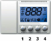
- Simultaneously press the keys 2 and 3, keep them pressed for at least 5 second to access the programming menu (the display shows “1”) .
- Press key 2 (once) to show the parameter “9”.
- Press key 4 to access the value of parameter 9. On the display it will appear the icon of the “phone cornet” and the address (by default this value is “30” – first thermal zone).
- Choose the number of thermal zone that one wishes to set (from 30 to 37) using the keys 2 and 3.
- Confirm the setting shown on the display with key 4. The thermostat will beep (acoustic signal) for confirmation and show back “9”.
- Waiting 5 seconds the thermostat will return to show the temperature.
![]() The thermal zone 8 (address 37) can not be used in the 4-pipes management.
The thermal zone 8 (address 37) can not be used in the 4-pipes management.
The home automation devices that the automation system can manage and integrate are many. This paragraph briefly illustrates which they are, how they must be programmed and the function they performed. For further information concerning the home automation devices (technical specifications, limitations, connections, etc.) refer to the instruction manual available for download on AVE website or on AVE Dominaplus catalogue.
Home automation devices can be used in two ways:
- ASSOCIATED DEVICES: These devices are managed automatically by the control unit, on the basis of particular events and/or working modes.
- GENERIC DEVICES: These devices can be controlled locally (manually) and/or remotely (with the supervision software).
The tables below list the above mentioned devices under the two conditions, along with the AVEbus address to be associated and the function to be set (through PRAB01 or SFW-BSA).
| item | address | function | associated function | notes |
| 53AB-ECO | 0x10 | 7 | Energy saving device | |
| 44xABT1 | 0xA0 to 0xAF | 1 – 2 | Scenarios Command | Scenarios 1 to 16 |
| 44xABR1 | 0x01 | 1 | Courtesy light output | Associated to the outdoor reader 0 |
| 44xABR1 | 0x02 | 1 | Courtesy light output | Associated to the outdoor reader 1 |
| 44xABR1 | 0x03 | 1 | Courtesy light output | Associated to the outdoor reader 2 (commonareas only) |
| 44xABR1 | 0x04 | 1 | Courtesy light output | Associated to the outdoor reader 3 (commonareas only) |
| 44xABRTM01 | 0x10 to 0xE0
(10, 20, 30 etc..) |
1 | Valves output
(4 pipes management) |
A couple of valves every thermostat (maximum 7 thermostat). The first (0x10) is the hot water valve, the second is the cold water valve (0x20) |
| 44xABTA | 0x01 | 2 | Alarm “Emergency” (manual reset) | |
| 44xABTA | 0x02 | 2 | Alarm “Ventilation” (manual reset) | |
| 44xABTA | 0x03 | 2 | Alarm “Generic” (manual reset) | |
| 44xABTA | 0x04 | 2 | Alarm “Ventilation” (automatic reset) | |
| 44xABTA | 0x05 | 2 | Alarm “Generic 1” (automatic reset) | |
| 44xABTA | 0x06 | 2 | Alarm “Generic 2” (automatic reset) | |
| 44xABTA | 0x30 to 0x37 | 2 | Alarms 9-16 (manual reset) | Generic additional alarms (manual reset) |
| 44xABTA | 0x38 to 0x3F | 2 | Alarms 9-16 (automatic reset) | Generic additional alarms (automatic reset) |
Table 1 – Home automation: Associated Devices
| item | address | function | associated function | notes |
| 44xABT1 | 0x01 | 3 | Courtesy light command | Associated to the outdoor reader 0 |
| 44xABT1 | 0x02 | 3 | Courtesy light command | Associated to the outdoor reader 1 |
| 44xABT1 | 0x03 | 3 | Courtesy light command | Associated to the outdoor reader 2 (commonareas only) |
| 44xABT1 | 0x04 | 3 | Courtesy light command | Associated to the outdoor reader 3 (commonareas only) |
| 44xABT1 | 0x30 to 0x3F | 1 – 2 | Generic lights command | |
| 44xABR1 | 0x30 to 0x3F | 1 | Generic lights actuator | |
| 44xABRT01 | 0x30 to 0x3F | 1 | Shutters command and actuator | |
| 44xABDI | 0x30 to 0x3F | 1 | O-10V dimming actuator | |
| 44xABTA | 0x30 to 0x37 | 2 | Alarms 9-16 (manual reset) | Generic additional alarms (manual reset) |
| 44xABTA | 0x38 to 0x3F | 2 | Alarms 9-16 (automatic reset) | Generic additional alarms (automatic reset) |
| 44xABTA | 0x40 to 0x4F | 2 | Generic inputs | Status detection only |
| 44xAB68 | 0x40 to 0x4F | 1 | IR Detectors | Status detection only |
Table 2 – Home automation: Generic Devices
The hotel management software is provided on support CD-ROM in a suitable custody on which is clearly visible the code of the product.
The code SFW-ALBxx identifies three different products (xx indicates the identification number of the software) to choose depending on the system size (maximum number of control units connected to the system).
![]() The number of control units is obtained by summing the total number of room control units (cod. 53AR01-485) with that of the common area control units (cod. 53AR02-485).
The number of control units is obtained by summing the total number of room control units (cod. 53AR01-485) with that of the common area control units (cod. 53AR02-485).
Before starting the installation of the software, verify that the purchased product corresponds to the needs of its structure. The versions proposed by AVE are the following :
- SFW-ALB05 for systems with a number of control unit included between 1 and 20
- SFW-ALB06 for systems with a number of control unit included between 21 e 50
- SFW-ALB07 for systems with over 50 control units.
The management software is essentially composed by two parts. A service that cyclically manages the communication from and toward the control units (defined as Server in the continue of the present document) and an “application” for interfacing with the user (defined as Client in the continue of the present document). While the Server must be installed only on one computer connected to the AR-NET01, the Client application can be installed on several computers.
The automation software has been studied, realized and tested to work and guarantee optimal performances on computers where are installed Microsoft Windows ® systems.The computer on which the Server is installed must be reserved only for this purpose and on this PC other application programs besides those provided with that operating system must not be installed. Only exception admitted is that on the same computer is installed also the application User or Client.
The minimum requirements of the PC on which the Software will be installed are:
- Windows 7 (edition of 32 or 64 bit)
- 2 GB RAM
- 100 Mb of free memory on HDD
- No software installed besides those given with the operating system
- Net card 10/100 base-T
- CD ROM/ DVD reader
The minimum requirements of the PC on which Client ([3]) will be installed are:
- Windows 7 (edition of 32 or 64 bit)
- 2 GB RAM
- 100 MB of free memory on HDD
- Graphic card with minimum resolution 1024×768 24bit (monitor 4:3)
- Graphic card with minimum resolution 1280×768 24bit (monitor 16:9)
- Net card 10/100 base-T
- Port USB 2.0
- CD/DVD ROM reader
- Internet connection for remote assistance
- Software for remote assistance (TeamViewer)
 AVE S.p.A. reserves the possibility not to intervene in case of possible malfunctions of the software if it is installed on computers that do not respect the minimum requests characteristic or if it is installed, through the use of a virtual machine, on operating systems different from the requested one.
The installation of the software package is divided into two parts, Server installation and then Client installation.The procedure for installing the software package on the computer (or computers if server and client are on different PCs) is the following:
Installing Server application
- Insert the CD-ROM containing the software “Domina Hotel Management” in the reader of the PC on which it will have to be installed the application Server.
- After few seconds it will automatically open the default browser (e.g. Microsoft Internet Explorer ®) with the screenshot shown in the figure.
- If the file does not run automatically, manually browse the CD-ROM folder and double click on the file “Start.bat”
 Install the Server application clicking on the icon on the left (see figure) and then follow the instructions that the installation program will report in the window. If the browser requires it, confirm the reliability of the software to be able to go on with the installation procedure.
- When installation is completed close the browser and remove the support CD-ROM “Domina Hotel Management” from the reader.
 Install the Server application clicking on the icon on the left (see figure) and then follow the instructions that the installation program will report in the window. If the browser requires it, confirm the reliability of the software to be able to go on with the installation procedure.
Installing Client application
- Insert the CD-ROM containing the software “Domina Hotel Management” in the reader of the PC on which it will have to be installed the application Client.
- After few seconds it will automatically open the default browser (e.g. Microsoft Internet Explorer ®) with the screenshot shown in figure.

- If the file does not run automatically, manually browse the content of the CD-ROM and double click on the file “Start.bat”.
- Install the application Client clicking on the icon on the right (see figure) and then follow the instructions that the installation program will report in the window. If the browser requires it, confirm the reliability of the software to be able to go on with the installation procedure.
- When the installation is completed close the browser and remove the support CD-ROM “Domina Hotel Management” from the reader.
- On the computer’s desktop will now be available the link for the application Client (DHSys Client), see icon shown in the figure. It is possible to access to the application also through the Windows ®’s “Start” menu in the folder “Programs (x86)\AVE\DHSys\DHSys Client”.
 Install the application Client clicking on the icon on the right (see figure) and then follow the instructions that the installation program will report in the window. If the browser requires it, confirm the reliability of the software to be able to go on with the installation procedure.
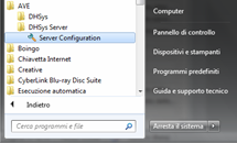 To be able to use the software it is necessary to activate the user license. This operation must be performed on the computer on which the Server application is installed.
From the Windows ® “Start” menu select the folder “AVE/DHSys Server” and launch the application “Server Configuration” (see figure).
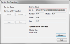 After a few moments it will appear the main screenshot of the application (see figure).
Before proceeding to the activation it is necessary copying the PC ID code (visible in the red rectangular box) and communicate it by telephone or by email to the InTeam office of AVE jointly to the name of the structure that requests the activation and the code of the Master card associated to the structure.
This information is essential for the generation of the correct key activation code of the Server application that will be communicated subsequently by InTeam.
 The software activation key will generate a file of license “License.lic” specific for the computer in use. Moving the license obtained by a computer to another is not possible, as it is not valid on a PC different from the one on which it was activated.
If it is necessary replacing the computer for breakdowns and/or other reasons it is necessary to inform before the InTeam office to agree the generation of a new activation code. A maximum of two replacements are allowed, for further replacement it is necessary to acquire a new license.
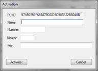
After obtaining all the necessary data, click “Activate…” and wait for the visualization of the activation screenshot (see figure). Now all the fields with the previously obtained data must be filled in, and, in particular:
- Name Computer’s name, agreed with InTeam, for which was asked the activation of the service
- Number Number of associated PC (communicated by InTeam office )
- Master Master card’s code (plant code) associated to the structure that has to be activated
- Key Activation key produced and provided by the Inteam office
 Name Computer’s name, agreed with InTeam, for which was asked the activation of the service
After filling in all fields and checked again that the values are correct, click on “Activate!” to generate the license file. If everything was done correctly, it will appear the confirmation message “Activation performed Correctly”. Otherwise it will appear the error message “Activation key incorrect!”.
If it was all performed correctly the activation screenshot will close automatically, showing back the main screenshot but with the button “Install” enabled. Click on the button “Install” to install the windows service.
At the end of the operations it will appear the confirmation message “Operation Complete” and will be enabled the keys “Uninstall” and “Start”. At this point the service is installed with user license activated, but not yet running. Therefore click on the button “Start” to start the Server service.
The figure alongside illustrates the main screenshot at the end of all the operations (started service). Click on the button “Exit” to go out from the application of license activation (the Server service will however remain active).

The Server service is installed as an autorunning task, in a way that after every restart (or switching on) of the PC, the service will automatically activate without the user having to execute any manual operation.
The installation program seen above installs, besides the services and applications, also a blank database which will have to be configured according to the structure that one desires to manage and monitor. The plant database is filled-in through a configurator integrated in the application DHSys Client.
To start the program click on the icon placed on the desktop and wait the visualization of the user login window. At the first start, until when a new user with access privileges to the system is created, it is possible to login using default username and password. Username: “admin” – Password: “password”.
 For security reasons it is highly recommended, once created the users with the access privileges (see following paragraphs), to remove the default user to avoid accesses to the application DHSys Client from not authorized people.
 To make the access it is necessary, above all, type in the IP address of the computer on which the Server service is installed. In case both the Server and the Client were
installed on the same computer it is possible typing in, as IP address of the server, also the value “127.0.0.1” (local host).
If the address of the Server is unknown please contact the network Administrator to obtain the information. Once typed the IP address of the server type the Username and the Password and then click on the button “Connect” .
If the values are correct the Client will connect to the Server and then will visualize the main page of the application.
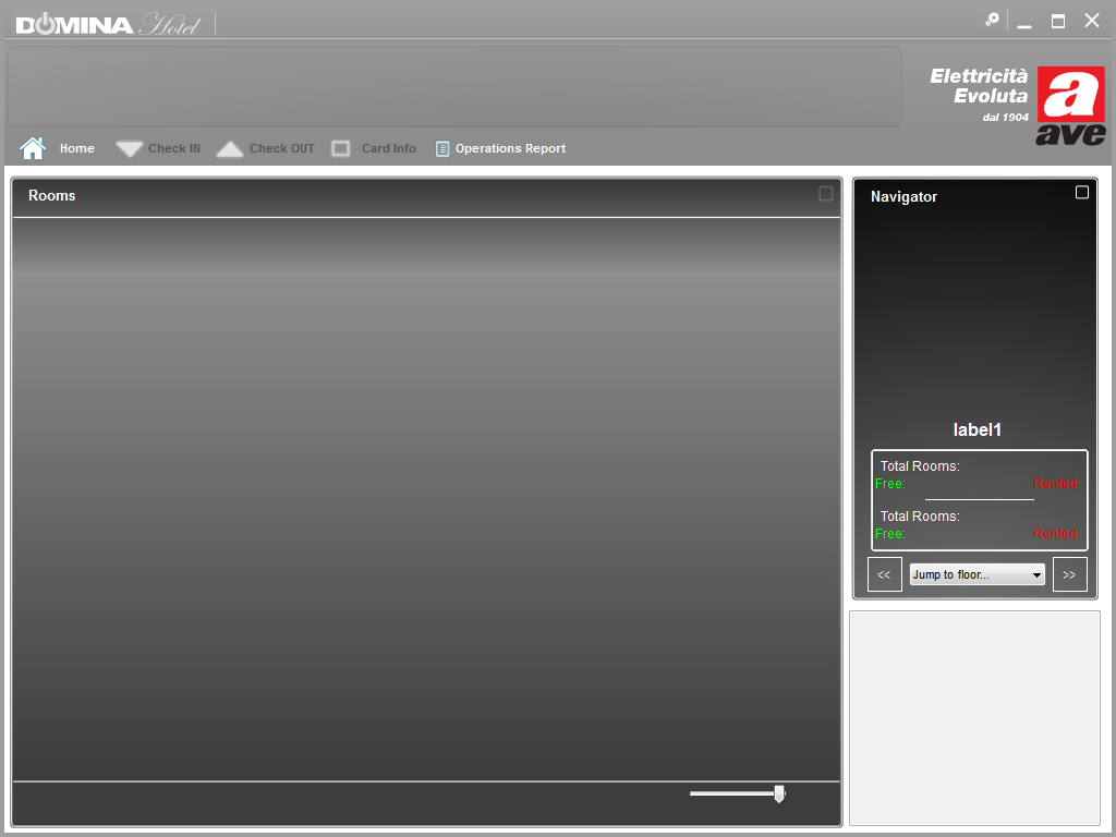
Screenshot DHSys Client at first starting
As visible in the figure shown above, at the first start the Client does not contain any data. The following paragraphs illustrate how to populate the database with the information of the plant and so being able to visualize them on the application DHSys Client.
 To be able to access the configurator it is necessary to click on the icon with the two gears placed on the right of the title-bar (see figure).The default user “admin”, has the highest privilege level which enables it to access also to the configurator.
 Subsequently it will be possible to create user profiles with restricted access privileges (typically the receptionist is not authorized to change the configuration of the plant, while maintenance personnel is).
The access window on the side is shown when a full privileges account enters into the configurator (when a limited account enters the configurator only some menus are available).
The setting of the system parameters regards the customization of the Client application and therefore does not modify the settings of the other Clients installed on the other computers.
To modify these settings one must choose the “System parameters” field from the list on the left column (see previous paragraph figure).
This menu allows to choose the language of the Client application for the user (Italian/ English) and the scale to be used for the visualization of the temperatures (Celsius/ Fahrenheit). These two options are available in combo lists “Language” and “Show Temperatures in”.
There are also other two check boxes for further customizations; the first (“Enable Advanced graphics”) allows to enable an more pleasant graphic interface of the Client (this box normally is checked as the standard graphic cards allow this management without the speed of the computer being affected). The second (“Thermoregulation Monitor mode”), when selected, turns the Client into a simple monitor that checks and shows the status of the thermoregulation of common area control units only.
In this case the Client will not show any information other than the thermoregulation of common areas, so that signals regarding alarms, presences, status of the rooms and so on, will not be reported on this of Client . Once customized the application, click on the button “Save” to confirm. The typical configuration is reported in the image of the previous paragraph.
 Every single Client can be used to program and issue the cards, both for the guests and the service staff. To do that, a programmer of AVE cards (article SCR- ALBM1) must be physically connected via USB to the PC. In this page of the configurator it is possible to set the number of the COM port where the card programmer is connected.
Before modifying this setting please assure the programmer is connected to the computer and that is working (the yellow hourglass icon on the programmer must be blinking while the other icons are off). In the window ALBM-01 parameters the programmer status appears as “OFFLINE”.
Choose then from the combo list “COM port” the port of communication where the programmer is connected. If it does not appear, click on the “Refresh” button to execute a new research. If also in this way the COM port does not appear it is necessary to check again the connection cable and/or settings assigned by Windows ® to the device SCR-ALBM1 (from Control Panel/ System/ Devices Management).
Once the communication port has been properly detected, select it in the combo list and then save the settings by clicking on the “Save” button. At this point on the programmer the LEDs that indicate USB activity should flash as well as the LED that receive the messages (green LED with check mark icon). Reopening the configurator, the programmer status will be “ONLINE” (see figure).
As previously seen for the system’s parameters, also the parameters concerning the programmer SCR-ALBM1 are local for the Client and will not affect different possible settings of another Client with another programmer.
 To execute the first configuration of the plant or for possible following modifications and/or extensions it is necessary entering in the application that interacts with the database of the plant. For obvious reasons, during this phase, in case of maintenance of an already started plant, the Server service is temporary suspended to allow the configurator to introduce the required modifications to the database.
The configurator is a critical application and thus it is password protected. The default password is: “password”. Therefore type in the password (which can be lately modified) and click on the button “Start Configurator ”
 The access password for the configurator password must be known only by the personnel responsible for the configuration/ administration of the plant; they must be aware that erroneous changes made on the system parameters can cause malfunctioning of the automation plant.
If the password is correct the main window of the configurator will be shown (see figure). Each button allows to enter a different menu where it is possible to (define and/or modify) the plant configuration. The following paragraphs will illustrate the meaning and the function of every single button of the configurator.

Main screenshot of the configurator
 Clicking on the key “Exit configurator” the application restores the “Server” service and sends to all the nodes the new configuration of the plant. The required time to send all the parameter to all the devices in the plant can change according to the number of control units connected to a single AR-NET01 gateway (typically a couple of minutes for structures with 50 rooms and 10 common areas under the same AR-NET01).
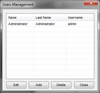 Clicking on the button “User Management” it is possible to manage the users allowed to access the system. From this window it is possible to create new users and select their “privileges”.
After selecting a user from the list, it is possible to delete it by clicking on the “Delete” button or modify the parameters by clicking on the “Edit” button (these two buttons have no effect unless it is first selected a user from the list displayed in the window). Clicking instead on the button “Add” one creates a new user. Both the button “Edit” and the button “Add” open the user data box where it is possible to set or edit the user information and privileges (figures A and B), if a parameter cannot be modified it will appear like those in red rectangular frames in figure B.
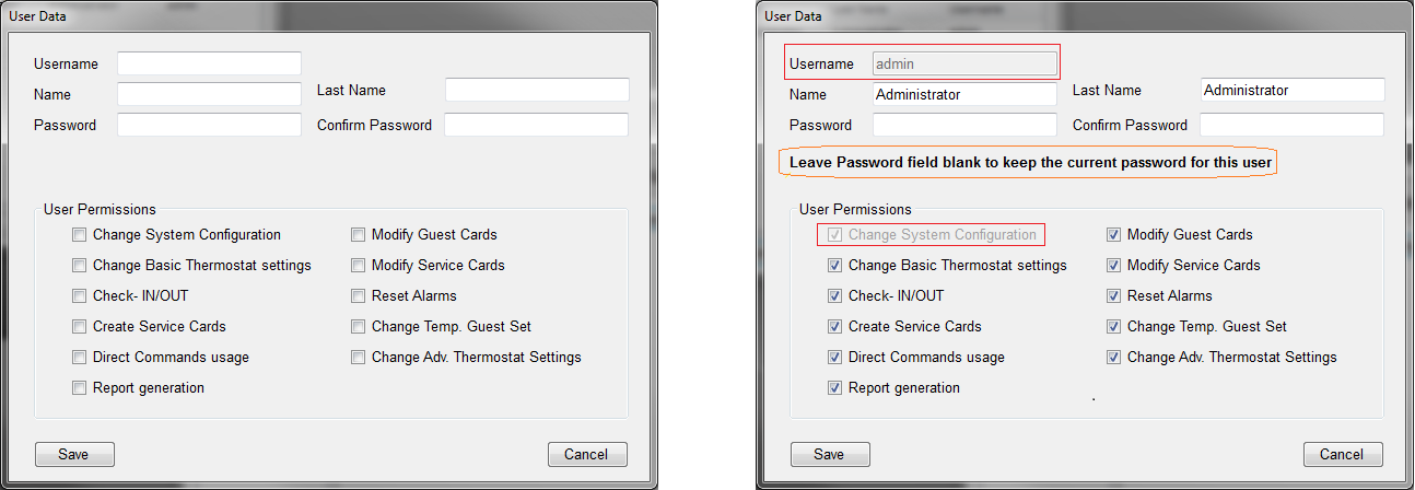
A) Add a new user B) Modify an existing user

When modifying a user data (only for full privileges accounts) it is possible to replace the current password with a new one even without knowing the former one to avoid the need to recreate a new user if the old password is lost. If one does not want to change the password it is essential not to fill in the fields “Password” and “Confirm Password” as also shown in the entry mask (orange box).
In the mask of creation and/or modification of the user it is possible to define the following user information:
- Username Name or nickname of the user (used jointly to Password for the Login to the application DHSys Client)
- Name User name
- Last Name User’s last name
- Password Password assigned to the user (used jointly to Username for the Login to the application DHSys Client)
Type in the password a second time in the Confirm Password field to avoid mistakes.
For each user it is also possible to define the access privileges (which functions of the program can access):
- Change System Configuration: Defines whether the user can access to the system configuration (access to the configurator)
- Change Basic Thermostat settings: Defines whether the user can modify the basic parameters of the thermoregulation (e.g. temperature set and speed of the fan-coil)
- Check-IN/OUT: Defines whether the user is enabled for the check-in and check-out of the rooms (guest’s management)
- Create Service Cards: Defines whether the user can create new cards for the staff (maid, maintenance, safety etc…)
- Direct Commands use: Defines if the user is enabled to modify the status (on / off) of direct commands configured for rooms and/or common areas
- Report generation: Defines whether the user is enabled to generate reports through the application (eg. Card detections from room readers)
- Modify Guest Cards: Defines whether the user is enabled to modify the datas stored in the guest cards
- Modify Service Cards: Defines whether the user is enabled to modify the datas stored in the staff cards
- Reset Alarms: defines if the user is enabled to reset the alarms coming from the rooms/common areas
- Change Temp. Guest Set: Defines whether the user is enabled to modify the temporary set temperature of the guest
- Change Adv. Thermostat Settings: Defines whether the user is enabled to modify the parameters of advanced thermoregulation
At the end of the modifications and/or the data editing click on the button “Save” to update the database.
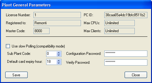 Click on the “General Parameters” button to access the configuration of the system parameters as shown in the figure. Some of these parameters are not modifiable as linked the user license.
Unchangeable parameters are shown in the upper part of the screenshot.
The lower part reports the values that can be modified by the user which are:
- Sub-Plant code: Code of the Sub Plant associated with the structure. For each code Master it is possible to associate multiple sub-plants (up to a maximum of 8 – numbered from 0 to 7), if there is the need to provide access of the card to more than one hotel structure.
- Configuration password: Allows the modification of the password necessary to access to the configurator (the default password is “password”)
- Default card expiry hour: default time for check-out, at this time on the check-out date the card expires. For particular demands the time of expiry of the single card can be modified directly in check-in phase
Type in the password a second time in the Verify Password field to avoid mistakes.
Unchangeable data are:
- License Number: license number assigned to the computer
- Registered to: name associated to the license registration
- Master code: Master card code associated to the plant (this hexadecimal string is printed in the lower right corner of the Master card provided to structure)
- PC ID: identification number of the computer associated to the license
- Max CPUs: maximum number of control units that can be managed by the software installed
- Max Clients: maximum number of DHSys Client applications that can be simultaneously connected to the Server
At the end of the data editing click on the button “Save” to update the database.
Clicking on the button “Floors” one can access the configuration of the floors where it is possible to add, modify and/or remove the floors for the structure. Typically the floors are the first element to be create as, both the rooms and the common areas, will have to be bound to the corresponding floor to be able to visualize them subsequently by the Client.
 The list on the left reports the floors currently registered in the database. Clicking on an element of the list the data of the element are shown in the box on the right (Floor Data) where they can be modified and therefore saved by clicking on the button “Save”. Clicking on the icon “Add Floor ” a new floor will be created in the list on the left, whose data will be able to be modified in the box on the right (Floor Data).
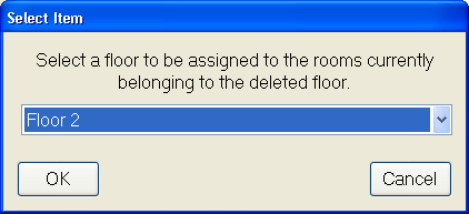
To remove a floor already created select it from the list on the left and click on the button “Delate Floor”; a window will appear to enable the user to automatically rebound the rooms associated to the delated floor to another floor. Choose the floor desired from the proposed list and confirm the choice with OK to complete the procedure. At the end of floors configuration click on “Close” button.
 Clicking on the “Room types” button one accesses to the configuration of the room types present in the structure. From this window it is possible to add, modify and/or remove the room types. Similarly to the floors, room types are also among the first elements to be created. The rooms that will be created after will have to be associate to a room type between those defined in this window.
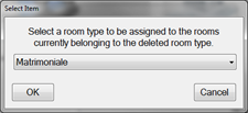 The left list shows the data currently in the database. Clicking on an element of the list the item’s data are showed on the right (Room Type data) where they can be modified and then saved by clicking on the button “Save”. By clicking on the “Add Type” button a new room type will be created in the left list whose data can be edited and modified in the frame on the right (Room Type data). To remove an already created type, select it from the list on the left and then click on the button “Delete Type”. It will appear the window on the right in which it is asked to which type to associate the rooms already created and associated to the type of room is being deleted.
Choose the type desired from the list proposed and confirm the choice with OK to complete the procedure. At the end of the floor’s configuration click on “Close” button to exit.
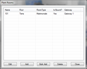 Clicking on the “Rooms” button one accesses the configuration of the rooms present in the structure (Plant Rooms). From this window it is possible to add, modify and/or remove the rooms. To generate the new rooms of the structure one can proceed in two ways.
Either adding rooms one by one or creating a block of rooms starting from the configuration of a previously created one. It is therefore a good rule, in order to accelerate the creation of the rooms operations, to create a single room separately to use as default to subsequently create the already preconfigured room blocks with the same characteristics as those of default.
If some rooms have particular managements that are different from that foreseen by default it will be however possible to modify them by clicking on the button “Edit”.
Creating the default room (Add)
To create the default room click on the button “Add”. It will be shown the mask for the creation of the room as shown in figure.

Mask for the creation of the default room
Now insert the data concerning the configuration of the default room by taking into account the meaning of the several elements to define that are:
General Parameters:
- Name: Name or number to assign to the room. This name is shown on the reports and on the detail about the room
- Short Name: Name or number to assign to the room. This name is shown on the room icon of the user interface and on the alarm popup. It must, wherever possible, be limited to 3-4 characters to be displayed correctly in every icon and at every display resolution.
- Courtesy Light: Defines the time (in seconds) during which the courtesy light stays on. The courtesy light lights up as a consequence of the reading of a valid card on the outdoor reader and it turns off automatically after this time
- Suppliers Timeout: Defines the maximum time of presence (in minutes) of the supply loads inside the room
- Power mode: Defines the kind of management of room FEM (loads supply). It is possible to choose between three different modalities:
- OFF: The FEM in the room is never active
- ON: The FEM in the room is always active
- BOUND: The status of the FEM is bound to the presence of a valid card in the indoor reader (active with valid card, not active in the other cases)
- Valve mode: Defines the type of management of the room sanitary water valve. It is possible to choose between three different modes:
- OFF: The valve in the room is always closed
- ON: The valve in the room is always open
- BOUND: The status of the valve is related to the presence of a valid card in the indoor reader (open with valid card, closed in other cases)
- Room Number: Assign to every room a progressive number, required for software purposes.
- Lock activation time: Activation time (in seconds) of the electro lock and/or the electrical interface for the access to the room. Typically for electrical interfaces with spring pivot one uses a variable time between 0,3″ and 0,8″ while for those without spring pivot the value changes between 3″ and 8″
- Light Timeout: Delay for the switching off of the room light (in seconds) starting from the moment in which the card is extracted from the indoor reader
- Control Unit: Room control unit (53AR01-485) address managing this room. With this parameter it will be generated the association between the id number of the room and the logical address of the room control unit. This list of selection is generated in an automatic way after the “Launch Discovery procedure” (cfr. par. 7.5.9). For this reason, during this first phase of configuration, skip this passage and leave the value “(not associated)”.
- Room Type: Type of the room (cfr. par. 7.5.4), eg. Single, Double, Suite, etc
- Floor: The floor where the room is (cfr. par. 7.5.3)
- Door bell when room is empty: Parameter that defines if the doorbell (button on outdoor reader) must also work when the room is not occupied (marked box) or only if the room is occupied by the guest (unmarked box)
- Turn on lights on guest entrance: Parameter that defines the status of the room light (room output managed by the room control unit) when a valid card is introduced in the indoor reader. If the box is marked the room light will lit automatically at the insertion of the card in the indoor reader. If the check mark is not present the light will start turned off and it will have to be turned on manually by the guest.
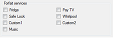 Forfait services:
It allows to set up the forfait services of which the room is supplied. Insert the check mark on those present and leave blank the not used boxes. This function is not yet manged by the system.
Alarms Logic and Alarms reset mode:
Manual Alarms Logic and Automatic Alarms logic:
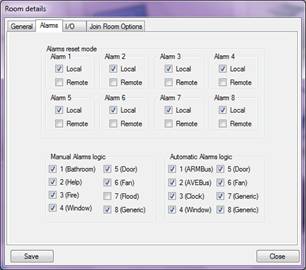 It allows to set up the logic of the alarm detection inputs (both manuals and automatic reset).
In the provided boxes the check mark must be inserted on the normally open detection contacts while the box must remain blank for those normally closed.
The figure illustrates the standard configuration of the detection inputs.
Alarms Reset Mode:
It allows to set up the way in which it is possible to reset the alarms that could activate in the room. For every manual alarm it is possible to set the reset mode (the automatic ones resets on their own when the alarm generating condition ceases). It is possible, for each of them, to define whether they can be rest remotely via software using the DHSys Client (box “Remote” marked), or locally from the room by means of a Security card placed in the indoor reader (box “Local” marked) or both ways. The figure illustrates the standard reset modes of the manual alarms.
At the end of the configuration of the standard room it is necessary to click on the button “Save” to update the database with the new data. To cancel the modifications made (exit without saving) click on the button “Close”.
Direct commands:
The Direct Commands menu (I/O) is made of four sub-menus that allow several configurations of the system. Below will be presented the different menus and the functionalities of the parameters in them contained.
Commands:
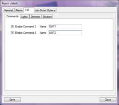 It allows to set up the direct commands present in the room (outputs directly controllable from the reception through DHSys Client software). Insert the check mark on those present and leave blank those that are not used. If the check is present it is possible to type in the text box on its side a description of the command (eg. FEM Minibar) that will be subsequently shown in the room detail near the command button.
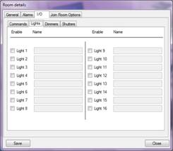
Lights:
It allows the configuration of the various home automation lights in the room. The system allows a maximum of 16 remotely controllable home automation lights. Insert a check mark on those present and leave blank the not used boxes. If the check is present it is possible to type in the text box on its side a description of the command (eg. Room light) that will be subsequently shown in the room detail near the command button.
The addresses to be programmed in the home automation devices (transmitter/actuator) are those included between 30 and 3F (lights Layer).For an optimal management of the devices it is recommended the following programming:
TRANSMITTER : Function = 3 (Step, without status feedback) or 14 (Step, with status feedback)
Parameter 1 = 1 (normally off at start up)
ACTUATOR 44..ABR1: Function = 1 (Instantaneous)
Parameter 1 = 0 (Delay on start and stop)
Parameter 2 = 0 (Normally open at start up)
![]() The programming of home automation devices must be performed using the device PRAB01 or through software SFW-BSA.
The programming of home automation devices must be performed using the device PRAB01 or through software SFW-BSA.
Dimmers:
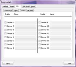 It allows the configuration of various home automation dimmer lights that are in the room.
The system allows a maximum of 16 configurable home automation dimmers. Insert a check mark on those present and leave blank the not used boxes. If the check is present it is possible to type in the text box on its side a description of the command (eg. Room dimmer) that will be subsequently shown on the room detail near the command button.
The addresses to be programmed in the home automation devices (transmitter/ actuator) are those included between30 and 3F (Layer Dimmer).For an optimal management of the devices it is recommended the following programming:
TRASMITTER : Function = 5 (without status feedback) or 14 (with status feedback
Parameter 1 = 1 (normally off at start up)
ACTUATOR 44..ABDI: Function = 1 (the only available)
Parameter 1 = 0 (normally open at start up)
Parameter 2 = 1 (minimum value at start up)
Parameter 3 = 1 (minimum range from 0 to max)

The programming of home automation devices must be performed using the device PRAB01 or through software SFW-BSA.
Shutters:
 It allows the configuration of various home automation shutters that are in the room.The system allows a maximum of 16 configurable home automation shutters. Insert a check mark on those present and leave blank the not used boxes. If the check is present it is possible to type in the text box on its side a description of the command (eg. Bathroom shutter) that will be subsequently shown on the room detail near the command button.
The addresses to be programmed in the home automation devices (transmitter/ actuator) are those included between 30 and 3F (Layer Shutter).
For an optimal management of the devices it is recommended the following programming:
TRASMITTER : Function = 6 (Without status feedback) or 15 (With status feedback)
Parameter 1 = 1 (normally off at start up)
ACTUATOR 44..ABRT01 : Function = see the table below
Parameter 1 = see the table below
![]() The programming of home automation devices must be performed using the device PRAB01 or through software SFW-BSA.
The programming of home automation devices must be performed using the device PRAB01 or through software SFW-BSA.
 Join room option
It gives the option to rent two or several associated rooms separately or together. At present time it is possible to associate a maximum of two rooms. The system will allow to associate up to five rooms with the next software releases.
Default common areas
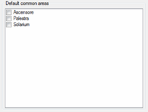 It allows to set which common areas the guest of this room will have access to by default, modification to this can be made in during check-in of every single guest. It is a small feature to save time for the receptionist.
If, for istance, the guests of a room are always enabled to the use the lift it is enough to check the corresponding box in this list and, at every check-in, the access to the lift will be proposed by default avoiding the receptionist to perform the operation manually. The common areas in the list are those defined as explained in following paragraphs.
Bulk rooms add
 To create a room block using the default room click on the button “Bulk Add” from the window “Add Rooms” (shown when one presses the button “Rooms” from the main window of the configurator). It will be shown the mask on the side in which some information will have to be inserted:
- Create room(s): Enter the number of rooms to be created, for example “12”.
- On floor: Choose from the list the floor where the rooms are, such as “Ground”.
- Starting with room code: Insert the first univocal code to be assigned to the room, for instance “8” (progressive and univocal number used for software purposes). NOTE: If some codes already exist they will be discarded by the software. For instance, if one wants to create “12” rooms starting from the univocal code “8” and the room with univocal code “9” turns out to be already present in the database, the software will create the rooms from 8 to 19 skipping the 9 that is already existing.
- Copying data from room: Choose from the list the number (or the name) of the previously created room (standard or default room) from which the software will copy the configuration parameters automatically.
After checking again the entered data click on the button “OK” to proceed with the creation of the room block.
At the end of the procedure, in the list “Plant Rooms”, the newly created rooms will be visible with name “Room xx” where ‘xx’is the iunivocal code assigned to the room.
 Clicking on the button “Gateway” one accesses the configuration of the Ethernet interface cod. AR-NET01 (or interfaces if the plant has more than one) where it is possible to add, modify and/or remove a gateway.
In the following paragraphs it will be illustrated how to associate the rooms to the control units and subsequently the control units to the gateways.
![]() In the list on the left are reported the gateways which have already been created. Clicking on an element of the list, the element’s parameters are showed in the box on the right (Gateway data) where they can be modified and then saved by clicking on the button “Save”.
In the list on the left are reported the gateways which have already been created. Clicking on an element of the list, the element’s parameters are showed in the box on the right (Gateway data) where they can be modified and then saved by clicking on the button “Save”.
Clicking on the icon “Add Gateway” a new gateway will be added in the list on the left, the parameters of the new gateway can be edited in the right box (Gateway data); the parameters are the IP address (format IPv4) of the AR-NET01, the communication port (always 7001) and the name to be associated to the gateway. To remove a gateway already created select it from the list on the left and then click on the button “Delete Gateway”.
The window shown in the following page will appear, in the same window it is asked to which gateway to associate the rooms and/or common areas already created and previously associated to the gateway that is being deleted. Choose the gateway desired from the list proposed and confirm the choice with OK to complete the erasing of the gateway. At the end of the configuration of the floors click on “Close” to exit.
After setting up all the basic elements (general parameters, users, floors, gateways) and having defined the rooms, it is necessary to proceed to the configuration of the common areas starting from the definition of the time slots.To access this configuration click on the “Time slots” button and wait for the visualization of the main screenshot (see following figure). From this window it is possible to add (up to a maximum of 32) modify and/or remove the time slots.
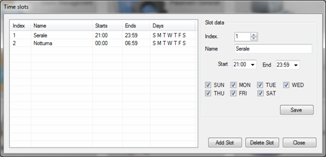 The list on the left reports the time slots present in the database. Selecting from the list a time slot it is possible to erase it by clicking on the “Delete slot” button. When the time slot is selected, all the parameters are shown in the box on the right (Slot Data), where it is possible, if required, to modify the settings. To create a new time slot it is sufficient to click on the button “Add slot” and the software will create a new time slot with default parameters and display them in the box on the right along with a message that confirms the creation of the new time slot.
Referring to the figure shown above, for each time slot must be defined the following working parameters:
- Index: Insert the ID univocal number of the time slot that must be included between 1 and 32
- Name: Insert an easily identifiable name for the time slot that reminds the settings, for instance “Evening”
- Start: Enter the time of activation of the time slot in the format HH:MM that must always be earlier than the one set as a parameter End. ([4])
- End: Enter the time of deactivation of the time slot in the format HH:MM that must always be later than the one set as a parameter Start.
- Days: Insert in the seven boxes (one for every day of the week) the check mark for all the days in which the slot is active. For instance, if one wishes that the “Night” slot has to be active only on Saturday and Sunday, the boxes “SUN” and “SAT” must be marked while the others must remain blank.
After checking again the entered data click on the button “Save” to store the new time slot in the database. After having inserted/modified all the necessary time slots, click on the button “Close” to go back to the main menu of the configurator.
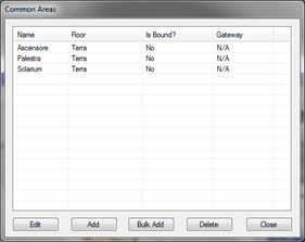 Clicking on the “Common Areas” button one accesses the configuration of the common areas present in the structure (Common Areas). From this window it is possible to add, modify and/or remove the common areas. To add new common areas of the structure one can proceed in two ways.
Either one by one or in block starting from the configuration of a previously created common area. It is therefore a good rule, to accelerate the creation of the common areas, to create separately, where possible, a single area to be used as default to create subsequently the blocks of common areas already preconfigured with the same features of the default one.
If some common areas have particular managements that are different from the default one it will be however possible to modify them by clicking on the button “Edit “.
Default common area creation (Add)
To create the default common area click on the button “Add”. The mask for its creation will be visualized as shown in the figure.
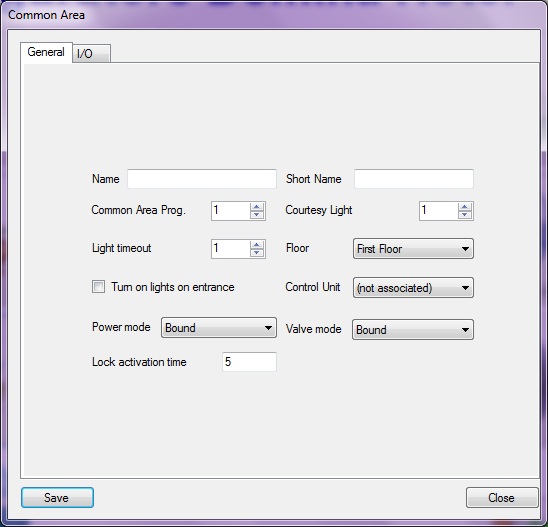
Mask to create the default common area
Now insert the data concerning the configuration of the default common area taking into account the meaning of the several elements to be define that are:
General Parameters:
- Name: Name or number to be assigned to the common area. This name is shown on the reports and on the detail about the common area
- Short Name: Name or number to be assigned to the common area. This name is shown on the common area’s icon on the user interface and on the alarm popup. It must, wherever possible, be limited to 3-4 characters to be displayed correctly in every mask and at every video resolution.
- Common Area Prog.: Progressive and univocal number to be associated to the common area used for software purposes.
- Courtesy Light: Defines the time (in seconds) during which the courtesy light stays on. The courtesy light lights up as a consequence of the reading of a valid card on the outdoor reader and it turns off automatically after this time.
- Light Timeout: Delay for the switching off of the common area light (in seconds) starting from the moment in which the card is extracted from the indoor reader
- Floor: The floor where the common area is (cfr. par. 7.5.3)
- Turn on lights on entrance: Parameter that defines the status of the common area light (direct output managed by the common area control unit) when a valid card is introduced in the indoor reader. If the box is marked the room light will turn on automatically at the insertion of the card in the indoor reader. If the check mark is not present the light will start turned off and it will have to be turned on manually.
- Control Unit: Common area control unit (53AR02-485) address managing the area. With this parameter it will be generated the association between the id number of the common area and the logical address of the common area control unit. This list of selection is generated in an automatic way after the “Launch Discovery procedure” (cfr. par. 7.5.9) for this reason, during this first phase of configuration, skip this passage and leave the value “not associated”.
- Power mode : Defines the kind of management of the FEM (supply of the loads) in the common area. It is possible to choose between three different modalities:
- OFF: The FEM in the common area is never active
- ON: The FEM in the common area is always active
- BOUND: The status of the FEM is bound to the presence of a valid card in the indoor reader (active with valid card, not active in the other cases)
- Valve mode: Defines the type of management of the common area sanitary water valve. It is possible to choose between three different modes:
- OFF: The valve in the common area is always closed
- ON: The valve in the common area is always open
- BOUND: The status of the valve is related to the presence of a valid card in the indoor reader (open with valid card, closed in the other cases)
- Lock activation time: Activation time (in seconds) of the electro lock and/or the electrical interface for the access to the room door. Typically for electrical interfaces with spring pivot, one uses a variable time between 0,3″ and 0,8″ while for those without spring pivot the value changes between 3″ and 8”
Before proceeding to the configuration of the status inputs and the direct commands it is necessary to store the common area in the database with the button “Save” and subsequently open again the configuration of the common areas.
Configuration I/O:
Direct Commands:
It allows to set up the direct commands (outputs directly controllable from the reception through DHSys Client software) available in the common area .
 In this box one must insert the check mark on the outputs (direct commands) that one wants to manage and leave blank the boxes of the not used outputs. If the check mark is present, the text box alongside enables, and it is possible to type a description to identify the command (eg. Swimming pool lights). This description will be subsequently shown in the detail window of common area, next to the button of the associated output.
The control unit associates an active status to a closed contact. To reverse this logic (active output with open contact) use a switchover relay. Direct commands 1 to 6 are are available on the terminals 10-11 (command 1), 12-13 (command 2), 14-15 (command 3) and from 16 to 18 with common on terminal 19 (commands 4 to 6) of the common area control unit (cod. 53AR02-485).
 Association of time slots to the commands
Every direct command of the common area, can be managed through software DHSys Client directly by the reception ad can also be associated to one or several time slots; the contact is closed whenever a least on time slot sets so (Boolean OR Logic).
Clicking on the button with the icon of a clock placed next to the direct command, the window of the set up time slots is shown (see figure). To associate the direct command to one or several slots it is sufficient to check the desired time slot (or slots) and confirm clicking on the button “Save”.

The time slots management logic is “events driven” that means that every time a slot is activated an action is performed. During the timeslot the outputs status can be modified. No control of the status of the outputs is executed except in the phase of “timeslot activation”.
Lights:
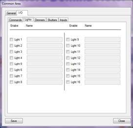 It allows the configuration of the various home automation lights in the common areas. The system manages a maximum of 16 configurables home automation lights. Check those present and leave blank the not used ones. If the check mark is present the text box alongside enables and it is possible to type a description of the light command (eg. room light) that will be subsequently shown in the room details near the icon of the command.
The addresses to be programmed in the home automation devices (transmitter/ actuator) are those between 30 and 3F (Layer lights).
For an optimal management of the devices it is recommended the following programming:
TRANSMITTER : Function = 3 (Step, without status feedback) or 14 (Step, with status feedback)
Parameter 1 = 1 (normally off at start)
ACTUATOR 44..ABR1: Function = 1 (Instantaneous)
Parameter 1 = 0 (Delay on start and stop)
Parameter 2 = 0 (Normally open at start)
![]() The programming of home automation devices must be performed using the device PRAB01 or through software SFW-BSA.
The programming of home automation devices must be performed using the device PRAB01 or through software SFW-BSA.
Dimmers:
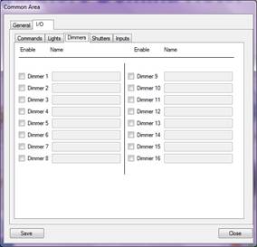 It allows the configuration of various home automation dimmed lights that are in the common area.
The system manages a maximum of 16 configurable home automation Dimmer. Check those present and leave blank the not used ones. If the check mark is present the text box alongside enables and it is possible to type a description of the dimming command (eg. Swimming pool dimmer) that will be subsequently shown on the room detail near the command icon.
The addresses to be programmed in the home automation devices (transmitter/ actuator) are those included between 30 and 3F (Layer Dimmer).For an optimal management of the devices it is recommended the following programming:
TRANSMITTER : Function = 5 (without status feedback) or 14 (with status feedback)
Parameter 1 = 1 (normally off at the start)
ACTUATOR ABDI: Function = 1 (the only available)
Parameter 1 = 0 (normally open the start)
Parameter 2 = 1 (minimum value at start)
Parameter 3 = 1 (minimum range from 0 to max)
![]() The programming of home automation devices must be performed using the device PRAB01 or through software SFW-BSA.
The programming of home automation devices must be performed using the device PRAB01 or through software SFW-BSA.
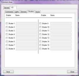 Shutters:
It allows the configuration of various home automation shutters that are in the common area.The system manages a maximum of 16 configurable home automation shutters. Check those present and leave blank the not used ones. If the check mark is present the text box alongside enables and it is possible to type a description of the shutter to be controlled (e.g. bathroom shutter) that will be subsequently shown on the room detail near the command icon.
The addresses to be programmed in the home automation devices (transmitter/ actuator) are those included between 30 and 3F (Layer Shutter).For an optimal management of the devices it is recommended the following programming:
TRANSMITTER : Function = 6 (without status feedback) or 15 (with status feedback)
Parameter 1 = 1 (normally off at start)
ACTUATOR ABRT01 : Function = see the table below
Parameter 1 = see the table below
![]() The programming of home automation devices must be performed using the device PRAB01 or through software SFW-BSA.
The programming of home automation devices must be performed using the device PRAB01 or through software SFW-BSA.
Inputs:
 It allows to set up the status inputs (inputs monitored directly from the reception through the software DHSys Client) that the common area must manage.
In this mask one must check the inputs to be managed and leave blank those which are not used. If the check mark is present, the text box alongside enables and it is possible to type a new description to identify the inputs (eg. Status of ground floor main circuit breaker) that will be subsequently shown on the common area detail next to the status icon (active/ not active).
Normally the inputs are considered active by the control unit when the contact is closed.
If one wants to reverse this logic (active input when contact is open), check the box “Invert” and the software will reverse the logic for the specific input. The inputs 1 to 6 are to be connected to terminals 3 to 8 of the control unit (common terminals 1 and 9).
Furthermore, for every input, it is possible to choose whether the activation of the input has to generate an alarm or not.
Bulk common areas add
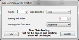 To create a common areas block using the default one, click on the button “Bulk Add” from the window “Common Areas” (shown when one click the button “Common Areas” from the main window of the configurator). The mask alongside will appear:
- Create area(s): Enter the number of common areas to be created, for example “4”.
- On floor: Choose from the list the floor on which create the common rooms, such as “Ground”.
- Starting with index: Insert the first univocal code to be assigned to the common area, for instance “2” (progressive and univocal number used for software purposes). NOTE: If some index already exist they will be discarded by the software. For instance, if one wants to create “4” common areas starting from the univocal code “2”, and the common area with univocal code “3” is already present in the database, the software will create the areas from 2 to 6 skipping the 3 that is already existing.
- Copying data from area: Choose from the list the number (or the name) of the previously created common area (standard or default area) from which the software will copy the configuration parameters automatically.
After checking again the entered data click on the button “OK” to proceed to the creation of the common areas block.
At the end of the procedure the new common areas will appear in the list as “Area xx” where ‘xx’ is the univocal number associated to the common area.
 ATTENTION: The creation of a common area group keeps all the parameters set up in the default common area except for possible associations between direct command and time slots of the area. It is necessary to edit the new common areas, and define manually the desired associations between timeslots and commands.
After setting up all the elements of the plant, as shown in the previous paragraphs, it is possible to proceed with the association between the control unit (of room or common area) and the elements in the database (rooms and common areas). Clicking on the “Control Unit” button on the main screenshot of the configurator the window below will appear.
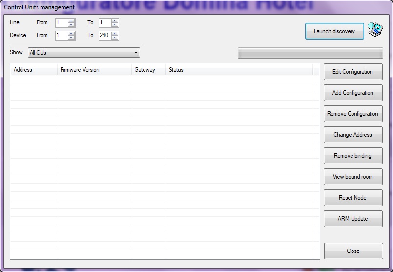
Select the range of lines (second group of digits in the control units address) and of devices (third group of digits in the control units address) to be scanned by the discovery procedure. The procedure will control all addresses in the ranges looking for control units connected to the system. The smaller the range is the faster the procedure. From the “Show” list select “All CUs” to indicate to the program to look for every control unit, both room ones and common areas ones, connected to the plant and then click on the button “Launch Discovery” to begin the automatic research. A little animation will indicate that the discovery procedure is running.
 Approximately, the system requires about two minutes to execute the complete research of all the nodes.
At the end of the research, all the control units detected in the plant will be listed. If the list turns out to be blank check again that the plant is powered on, that Ethernet and NETBus are properly connected, that the settings of the gateway are correct and that there are not firewalls that block the UDP traffic, and then execute a new devices research (Launch Discovery).
At the end of the discovery procedure the window here under will be displayed. Those CUs which were already bound to a room or control unit will appear as configured along with communication diagnosis (Responding/Not responding). New found CUs will appear as Not configured.
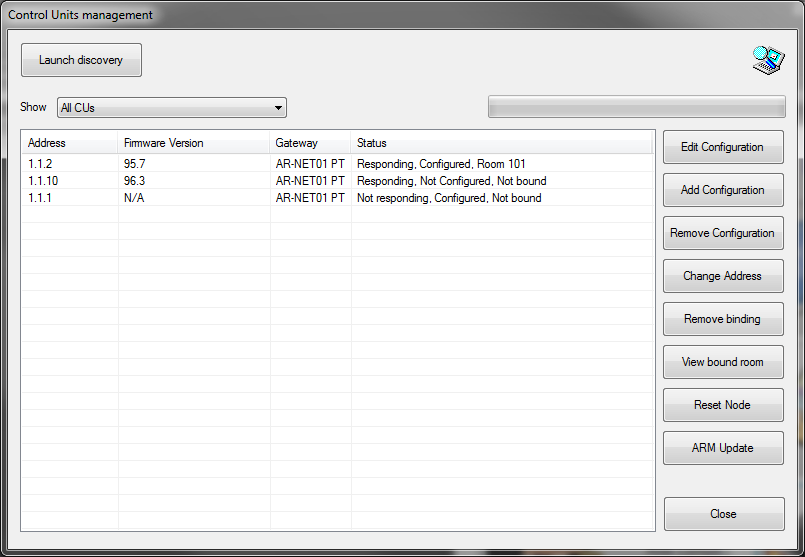
Result of Lauch discovery
The list shown in the above figure reports the following information:
- Address: CU’s NETBus address.
- Firmware Version: Version of the firmware (first two digits must be: 95 for room control units and 96 for common areas) and its revision index (last digit). If “N/A” appears it means that the control unit is present in the database but it was not detected on the plant.
- Gateway: It defines, in case of plants with more than one AR-NET01, the gateway to which the control unit is connected (in the case of a single gateway all the control units will have the same gateway).
- Status: Control unit’s status and configuration level divided in three parts:
- Communication: It defines whether the control unit connected to the bus responds to the gateway (Responding) or not (Not Responding).
- Configuration: It defines whether the control unit connected to the bus is present in the database (Configured) or not (Not Configured).
- Association: It defines whether the association between the control unit and the room (or common area) is present (eg. Room xxx or Common Area xxx) or not (Not bound).
After detecting all the control units it is possible to proceed to define the local configuration of the room or common area: devices connected (readers and/or thermostats).
This procedure is the same for rooms and common areas. The only difference is the number of devices that can be connected as already explained in previous chapters. Configurations of rooms with more devices than allowed are unacceptable and can result in malfunctioning of the system.
Local devices definition
![]() Select a control unit from the list and click “Edit Configuration” to define the which devices are connected.The window shown on the side will be displayed. One must pay particular attention in the configuration of the devices; if a device is physically present in the room but not configured, the control unit will not manage it and a warning message will be displayed in the DHSys Client software.
Select a control unit from the list and click “Edit Configuration” to define the which devices are connected.The window shown on the side will be displayed. One must pay particular attention in the configuration of the devices; if a device is physically present in the room but not configured, the control unit will not manage it and a warning message will be displayed in the DHSys Client software.
In the section “Configuration” check as many thermostat as are installed in the room (or in the common area) and type a description to identify the single thermostat. Do the same for outdoor readers (max 2 for the rooms) and indoor readers (max 1 for the rooms).
To save the configuration of the single room (or common area) click on the button “Save”.
If the configuration defined is identical to that of other rooms (or common areas) click on “Save Multiple” button and select the control units that have the same configuration (See figure below). Click on the button “OK” to confirm and go back to the list of the control units.
 ATTENTION: it is suggested, after completing the configuration of the CPUs to re-launch the discovery procedure in order to perform a system self-diagnosis and have the ability to verify the correctness of the system configuration. Enter again the configuration window of the single CPU and verify that all configured devices are marked with a green symbol.
If a red “X” or “!” appears on red background verify again the settings of the control unit and the physical wiring of the devices in the room (or common area).
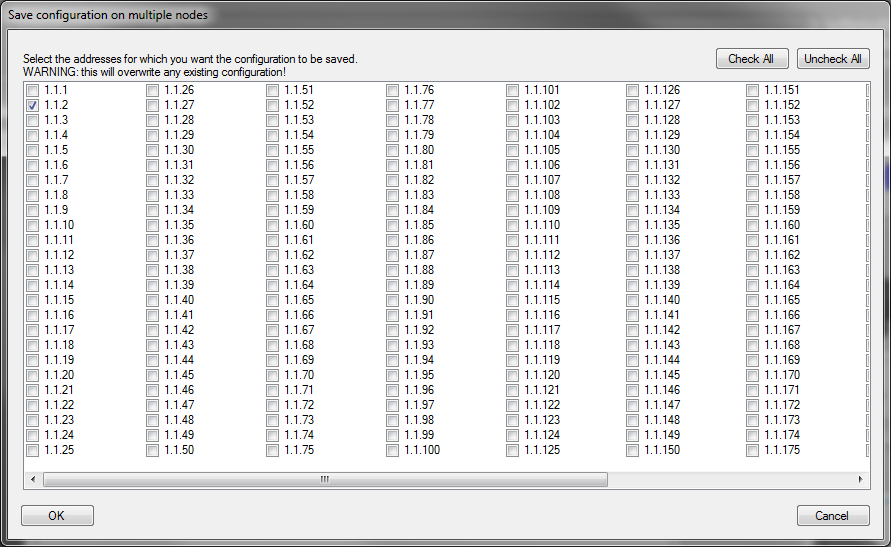
After executing all the operations of the present chapter it is now necessary defining, for every room or common area present in the database, the association between room (or common area) and control unit 53AR0x-485 choosing from the list Control Unit the address of the control unit to be bound.
To activate the association click on button “Save”.
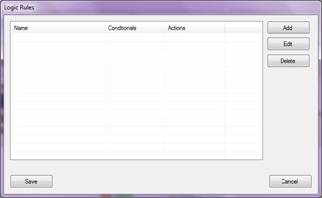 The logic rules window allow the user to create a list of events/commands to be executed on the basis of the status of different devices in the system.The user interface of the logic menu is shown on the side.
To create a new logic it is sufficient to click on the button “Add” which will open the window here under.

In the field “Name” it is possible to type the name to be assigned to this rule (note: it is possible to associate more conditions to an action).
To add a new condition click on the button “New”. The window here under, where it is possible to set the condition, will be displayed.
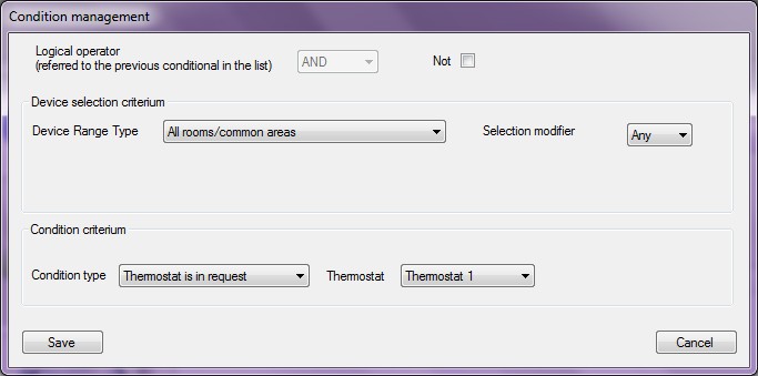
- Logical operator: chose the Boolean operation that the CU has to perform between this condition and the previous condition in the list (AND, OR). Click on the “Not” button to invert the operator (NAND, NOR).
- Device Range Type : device to which one associates the rule. The possibilities are shown in the image below:
- All rooms/Common areas: all the rooms or common areas of the plant. It is possible to choose (through the button “Selection modifier”) if the condition is verified only when the condition is verified by all CPUs (All) or from at least one of those present in the plant (Any).
- All Rooms/Common areas on a specific floor: choosing this option it will be shown a suitable menu through which it will be possible to select the desired floor.
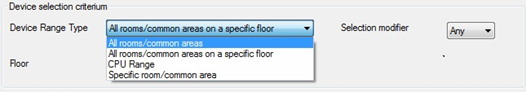 All rooms/Common areas: all the rooms or common areas of the plant. It is possible to choose (through the button “Selection modifier”) if the condition is verified only when the condition is verified by all CPUs (All) or from at least one of those present in the plant (Any).
It is possible to choose (through the button “Selection modifier”) if the condition is verified only when the condition is verified by all CPUs in the floor (All) or from at least one of those present in the floor (Any).
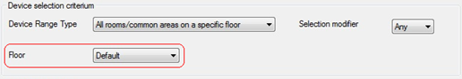
- CPU Range: it defines the CPU range that have to monitor this condition.
Range start = first CPU
Range end = last CPU
It is possible to choose (through the button “Selection modifier”) if the condition is verifier only when the condition is verified by all selected CPUs (All) or from at least one among those in the range (Any).

- Specific Room/Common area: it defines the association of the condition to a specific room or common area. The list of rooms and common areas configured is available in the drop down menu (procedure described in detail above).

In the lower part of the menu are inserted further criteria to verify the condition in those rooms or common areas previously identified.
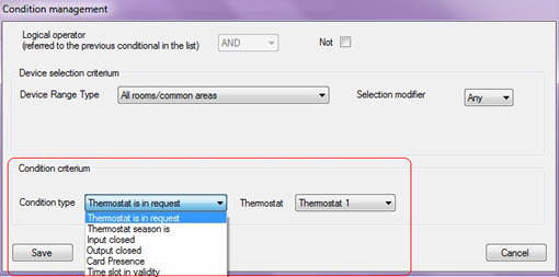
Possible conditions are:
- Thermostat is in request: the condition is verified if a certain thermostat turns out to be in request. Through the button “Thermostat” it is possible to choose whether the condition is verified only when a certain thermostat is in request or if at least one of the thermostats associated to the CPU is in request.
- Thermostat season is: the condition is verified if the selected thermostat settings correspond to the selected season: Summer, Winter, Intermediate (for this last only for plants with 4-pipes thermoregulation systems).
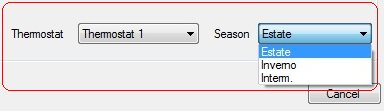
- Input closed: the condition is verified if the selected input of the CPU is detecting a closed contact.
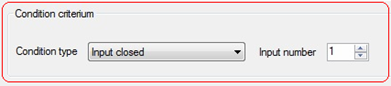
- Output closed: the condition is verified if the selected output of the CPU is closed.
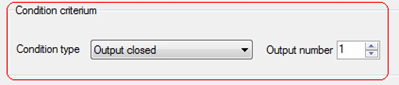
- Card Presence: the condition is verified if a certain card is inserted in the indoor reader of the room or common area.
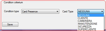
- Time slot in validity: the condition is verified if the selected time slot is active (see paragraph about time slots)
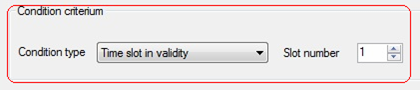
In case of damage or block of the supervisor PC or damage to the card’s programmer SCR-ALBM1, the hotel automation will keep on working with reduced functionalities until the problem is solved.
The possibility to give access to the room to new guests in case of system fault is guaranteed by “Super Guest” cards. “Super Guest” cards can be managed in two different ways:
Cards already created: (cfr. par. 9.1) If the “Super Guest” cards had been previously created, it is sufficient to give them to the new guests in order to give them access to the room (these cards have no expiration date and are not invalidated when a new guest card for the same room is created).
Cards to be created: If the “Super Guest” cards had not been create, it is possible, through the “Master” card of the plant, to create them using the outdoor reader of the room for which the card has to be created as card programmer. The procedure to program a “Super Guest” card on the outdoor reader is the following:
- Tap the “Master” card on the outdoor reader of the room until the reader beeps. Remove the “Master” card, verify that the green LED of the reader (key icon) is fixed on (not flashing).
- Touch the doorbell button of the reader for 4 times. At this point both the LED “key” (fixed light) and the LED “Do Not Disturb” (flashing) must be on.
- Tap the card to be programmed on the reader and wait for the confirmation beep (this operation might take few seconds) and then remove the card from the reader.
- Tap again the “Master” card on the outdoor reader until it beeps to terminate the programming procedure. The “key” LED must be flashing again.
- The card is now ready to access the room.
![]()
Remember to put back the Master card in a safe place after using it.
The preventive creation of the Super Guest cards through DHSys Client software is useful for the above mentioned reasons.
The procedure for the creation of these Super Guest cards is the following:
- Place a card on the programmer SCR-ALBM1 and wait the visualization of the window shown in figure.
- Select from the list “Card Type”, the option superguest.
- Select from the list “Room”, the number or the name of the room for which one wants to create the card (it is advised to insert the check mark on “No expiration” to have an always valid card).
- From the “Common Areas” list insert the check mark on those Common Areas to which the card must have access.
- Click on the button “Check IN” and wait for the program to show the confirmation message that the card was created correctly.
- Label the card with the number of the associated room and then store it in a safe place.
- Repeat the procedure for every room of the hotel structure.
 Place a card on the programmer SCR-ALBM1 and wait the visualization of the window shown in figure.
This chapter illustrates the products required for an online installation showing their pictures and describing terminal by terminal their use. Will be moreover illustrated the function performed by every LED, display and/or button that are present on the device.
The room control unit cod. 53AR01-485 is the main device for the automation of hotel rooms and is built in a 6 DIN module enclosure. It is provided of a series of extractable terminal blocks easily detectable since they are of different colors. It also has a display and seven buttons to interface with the user during the basic settings of the device.
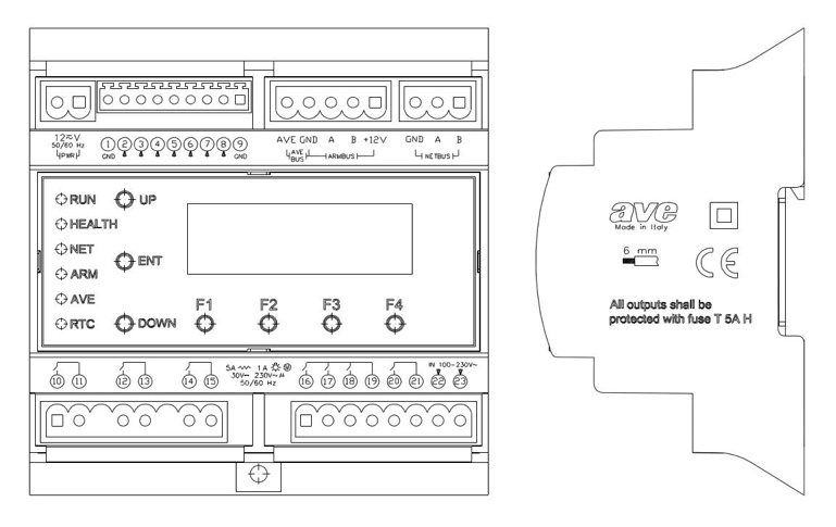

- Terminals
All the terminal blocks of the control unit are extractable, of colour and/or different shape to avoid mistakes during the connection and/or the replacement of the same terminals.
2 poles terminal (black) – SELV
name function
- 12V AC/DC Power feeding (non-polarized) of the control unit to be connected to a 12V ac/dc (50/60Hz)
9 poles terminal (green) – SELV
name function
- Ground reference for the inputs
- IN-1 Analog input 0-10V (flood probe)
- IN-2 Digital input (lock release push button)
- IN-3 Digital input (fire alarm repetition)
- IN-4 Digital input (do not disturb push button)
- IN-5 Digital input (door contact)
- IN-6 Digital input (bathroom emergency pull-cord)
- IN-7 Digital input (room light PUSH BUTTON)
- Ground reference for the inputs
5 poles terminal (red) – SELV
name function
- ave Bus home automation AVEBus positive
- gnd Ground for AVEBus and ARMBus
- Line “A” of the room bus ARMBus
- Line “B” of the room bus ARMBus
- +12V Positive for the room bus power supply ARMBus
3 poles terminal (blue) – SELV
name function
- gnd Ground for NETBus
- Line “A” of the backbone bus NETBus
- Line “B” of the backbone bus NETBus
8/6 poles terminal (green) – SELV or LV
name function
- OUT-1 (pole A) Output contact relay (electro lock command)
- OUT-1 (pole B) Output contact relay (electro lock command)
- OUT-2 (pole A) Output contact relay (water electro-valve command)
- OUT-2 (pole B) Output contact relay (water electro-valve command)
- OUT-3 (pole A) Output contact relay (direct command from pc)
- OUT-3 (pole B) Output contact relay (direct command from pc)
8/8 poles terminal (green) – LV
name function
- OUT-4 (pole A) Output contact relay (room light command)
- OUT-5 (pole A) Output contact relay (disabled bathroom alarm Sounder command)
- OUT-6 (pole A) Output contact relay (direct command from pc)
- COM4-6 (pole B) Common for output contact relays 4-6
- OUT-7 (pole A) Output contact relay (step by step relay command for main power activation)
- OUT-7 (pole B) Output contact relay (step by step relay command for main power activation)
- IN-Fb main voltage detection, feedback downstream the step by step relay (phase)
- IN-Fb main voltage detection, feedback downstream the step by step relay (neutral)
 The inputs, if not otherwise specified, are designed for the detection of dry contacts status. Outputs contacts are micro gap contacts with maximum current of 5A (resistive load) or 1A (inductive load). The sum of the absorptions of the outputs with common pole (terminals 16, 17 and 18) will not have to exceed 12A (resistive).
- LCD Display
The display, during the normal operation of the device, provides to the user some parameters as below illustrated.

X : Area where it is shown the type of the control unit installed (cod. 53AR01-485 for the management of the rooms)
X : Area where the firmware version installed in the control unit is reported (e.g., code 095 and 07 revision index)
X : Blank area
X : Alarm report. An “(A)” indicates that one or more alarms are active while a “(-)” indicates there are no active alarms
X : NETBus address of the control unit. The address is shown in hexadecimal format according to the coding “A.L.DD” (Area, Line, Device).
X : Area where it is shown the date/time in the format “GG/MM/AAAA HH:MM.SS”.
- User interface
The control unit is provided with 5 two-colored red/green LED plus a further additional green LED. The functions performed by these LEDs are the following:
![]() (RUN): Mode of operation of the control unit: (Fixed red light) indicates that the control unit is powering up, (fixed orange light) indicates that the CU is reading from the room devices the configuration data or that it is in “bootloader). (Green light blinking) indicates normal functioning.
(RUN): Mode of operation of the control unit: (Fixed red light) indicates that the control unit is powering up, (fixed orange light) indicates that the CU is reading from the room devices the configuration data or that it is in “bootloader). (Green light blinking) indicates normal functioning.
![]() (HEALTH): Status of health of the CU obtained from self-diagnosis test. Tested conditions are, listed in per importance (decreasing from the more severe one). This LED will always show, in case of several anomalies, the most severe one.
(HEALTH): Status of health of the CU obtained from self-diagnosis test. Tested conditions are, listed in per importance (decreasing from the more severe one). This LED will always show, in case of several anomalies, the most severe one.
- red (fixed): The internal voltage reference is broken/faulty. It is impossible executing correctly the measures on the analog inputs.
- green (fixed): with orange blinking (fast): The internal temperature of the board is more than 65°C for which may occur some malfunctions of some circuits of the control unit.
- orange (fixed): The value detected of the logical voltages of the mother board (3,3V and 5V) are beyond the admitted tolerances.
- green (fixed) with orange blinking (slow): The command voltage the drives the internal relays of the board and/or the one which feeds the home automation bus (AVEBus) are beyond the admitted tolerances or the internal bus I2C does not work properly.
- green (fixed): All the self-diagnosis procedures of the control unit gave positive result. No detected anomaly.
![]() (NET): Status of the backbone bus NETBus. The control unit report on this LED the status of this bus discriminating the following conditions:
(NET): Status of the backbone bus NETBus. The control unit report on this LED the status of this bus discriminating the following conditions:
- red blinking (slow): The control unit has not been polled from the supervisor for more than five minutes.
- green blinking (slow): has not been polled from the supervisor from more than five minutes.
- green (fixed): The control unit is cyclically polled by the supervisor system (at least one polling every two minutes). In this condition the frontal keypad to change the address is locked.
![]() (ARM): Status of the room bus ARMBus. The CU monitors whether the configured room devices corresponds to the actual devices connected to the bus and reports the result on this LED discriminating the following conditions:
(ARM): Status of the room bus ARMBus. The CU monitors whether the configured room devices corresponds to the actual devices connected to the bus and reports the result on this LED discriminating the following conditions:
- red blinking (slow): It has not been detected any device on the room bus. The cause could be the interrupted cable or a short circuit, or that the bus lines A and B are inverted on the connector ARMbus.
- green blinking (slow): It has been detected at least one device on the room bus ARMBus (the physical bus is working) but not all the configured devices are present.
- green (fixed): All the devices on the room bus ARMBus configured respond to the polling.
![]() (AVE): Status of the home automation bus AVEBus. The control unit executes a control between configured devices and devices detected on the room automation bus AVEBus and reports the result on this LED discriminating the following conditions:
(AVE): Status of the home automation bus AVEBus. The control unit executes a control between configured devices and devices detected on the room automation bus AVEBus and reports the result on this LED discriminating the following conditions:
- red (fixed): The voltage of bus (typically 13.8V) was not detected. This typically means that a short circuit is present or that a device on the bus is broken and is keeping the bus busy constantly.
- green blinking (slow): It has been detected at least one device on the room automation bus AVEBus that answers the polling (the physical bus is working) but not all the configured devices are present.
- green (fixed): The voltage on the home automation AVEBus is correct and all configured devices are responding to the polling, so there are not anomalies to report.
![]() (RTC): Status of the RTC of the CU. In normal working conditions must flash (0.5″ on and 0.5″ off). Fixed light (or turned off) means there is a problem at the RTC.
(RTC): Status of the RTC of the CU. In normal working conditions must flash (0.5″ on and 0.5″ off). Fixed light (or turned off) means there is a problem at the RTC.
 When the control unit 53AR01-485 is in standby (standby is activated if the keys are not pressed for over a minute), all the LEDs are switched off to avoid bothering the guest in conditions of low environment lighting.
- Push Buttons
The control unit is provided with 7 keys typically used in installation phase and/or for check-up. Their function is the following:
![]() (UP): Increment of the address NETBus of the control unit (only Device field). If the Device address is 0xFF (maximum allowed), clicking again on (UP), it will be restored to 0x00 (circular increase). This key is blocked when the control unit is correctly polled by the supervisor.
(UP): Increment of the address NETBus of the control unit (only Device field). If the Device address is 0xFF (maximum allowed), clicking again on (UP), it will be restored to 0x00 (circular increase). This key is blocked when the control unit is correctly polled by the supervisor.
![]() (DOWN): Decrement of the address NETBus of the control unit (only Device field). If the Device address is to 0x00 (minimum allowed), clicking again on (DOWN), it will be restored to 0xFF (circular decrease). This key is blocked when the control unit is correctly polled by the supervisor.
(DOWN): Decrement of the address NETBus of the control unit (only Device field). If the Device address is to 0x00 (minimum allowed), clicking again on (DOWN), it will be restored to 0xFF (circular decrease). This key is blocked when the control unit is correctly polled by the supervisor.
![]() (BKL): Button for the on/off commutation of the backlight of the LCD module (by default the backlight is active). This key is blocked when the control unit is correctly polled by the supervisor.
(BKL): Button for the on/off commutation of the backlight of the LCD module (by default the backlight is active). This key is blocked when the control unit is correctly polled by the supervisor.
F1 (DBG1) Function key to display diagnostic data – Absorptions
F2 (DBG1) Function key to display diagnostic data – Meters
F3 (DBG3) Function key to display diagnostic data – ARMBus
F4 (DBG4) Function key to display diagnostic data – I/O
The room control unit cod. 53AR02-485 is the main device for the automation of hotel common areas and is built in a 6 DIN module enclosure. It is provided of a series of extractable terminal blocks easily detectable since they are of different colors. It also has a display and seven buttons to interface with the user during the basic settings of the device.

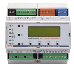
- Terminals
All the terminal blocks of the control unit are extractable, of colour and/or different form as to avoid mistakes during the connection and/or the replacement of the same terminals.
All the terminal blocks of the control unit are extractable, of colour and/or different shape to avoid mistakes during the connection and/or the replacement of the same terminals.
2 poles terminal (black) – SELV
name function
- 12V AC/DC Power feeding (non-polarized) of the control unit to be connected to a 12V ac/dc (50/60Hz)
9 poles terminal (green) – SELV
name function
- Ground input reference
- IN-1 Analog input 0-10V (flooD probe)
- IN-2 Digital input (generic input)
- IN-3 Digital input (fire alarm repetition)
- IN-4 Digital input (Generic input)
- IN-5 Digital input (door contact)
- IN-6 Digital input (bathroom emergency pull-cord)
- IN-7 Digital input (generic input)
- Ground reference for the inputs
5 poles terminal (red) – SELV
name function
- ave Power feeding/data bus home automation AVEBus
- gnd Ground for AVEBus and ARMBus
- Line “A” of the common area bus ARMBus
- Line “B” of the common area bus ARMBus
- +12V Positive for the common area bus power feeding ARMBus
3 poles terminal (blue) – SELV
name function
- gnd Ground for NETBus
- Line “A” of the backbone bus NETBus
- Line “B” of the backbone bus NETBus
8/6 poles terminal (green) – SELV or LV
name function
- OUT-1 (pole A) Output contact relay (direct command from pc)
- OUT-1 (pole B) Output contact relay (direct command from pc)
- OUT-2 (pole A) Output contact relay (water electro-valve command)
- OUT-2 (pole B) Output contact relay (water electro-valve command)
- OUT-3 (pole A) Output contact relay (direct command from pc)
- OUT-3 (pole B) Output contact relay (direct command from pc)
8/8 poles terminal (green) – LV
name function
- OUT-4 (pole A) Output contact relay (direct command from pc)
- OUT-5 (pole A) Output contact relay (disabled bathroom alarm SOUNDER command)
- OUT-6 (pole A) Output contact relay (direct command from pc)
- COM4-6 (pole B) Common terminal for output contacts 4-6
- OUT-7 (pole A) Output contact relay (step by step relay command for main power)
- OUT-7 (pole B) Output contact relay (step by step relay command for main power)
- IN-Fb main voltage feedback downstream the step by step relay (phase)
- IN-Fb main voltage feedback downstream the step by step relay (neutral)
 The inputs, if not otherwise specified, are designed for the detection of dry contacts status. Outputs contacts are micro gap contacts with maximum current of 5A (resistive load) or 1A (inductive load). The sum of the absorptions of the outputs with common pole (terminals 16, 17 and 18) will not have to exceed 12A (resistive).
- LCD Display
The display, during the normal operation of the device, provides to the user some parameters as below illustrated.

X : Area where it is shown the type of the control unit installed (cod. 53AR02-485 for the management of the common areas)
X : Area where the firmware version installed in the control unit is reported (e.g., code 096 and 03 revision index)
X : Blank area
X : Alarm report. An “(A)” indicates that one or more alarms are active while a “(-)” indicates there are no active alarms
X : NETBus address of the control unit. The address is shown in hexadecimal format according to the coding “A.L.DD” (Area, Line, Device).
X : Area where it is shown the date/time in the format “GG/MM/AAAA HH:MM.SS”.
- User interface
The control unit is provided with 5 two-colored red/green LED plus a further additional green LED. The functions performed by these LEDs are the following:
![]() (RUN): Mode of operation of the control unit: (Fixed red light) indicates that the control unit is powering up, (fixed orange light) indicates that the CU is reading from the room devices the configuration data or that it is in “bootloader). (Green light blinking) indicates normal functioning.
(RUN): Mode of operation of the control unit: (Fixed red light) indicates that the control unit is powering up, (fixed orange light) indicates that the CU is reading from the room devices the configuration data or that it is in “bootloader). (Green light blinking) indicates normal functioning.
![]() (HEALTH): Status of health of the CU obtained from self-diagnosis test. Tested conditions are, listed in per importance (decreasing from the more severe one). This LED will always show, in case of several anomalies, the most severe one.
(HEALTH): Status of health of the CU obtained from self-diagnosis test. Tested conditions are, listed in per importance (decreasing from the more severe one). This LED will always show, in case of several anomalies, the most severe one.
- red (fixed): The internal voltage reference is broken/faulty. It is impossible executing correctly the measures on the analog inputs.
- green (fixed): with orange blinking (fast): The internal temperature of the board is more than 65°C for which may occur some malfunctions of some circuits of the control unit.
- orange (fixed): The value detected of the logical voltages of the mother board (3,3V and 5V) are beyond the admitted tolerances.
- green (fixed) with orange blinking (slow): The command voltage the drives the internal relays of the board and/or the one which feeds the home automation bus (AVEBus) are beyond the admitted tolerances or the internal bus I2C does not work properly.
- green (fixed): All the self-diagnosis procedures of the control unit gave positive result. No detected anomaly.
![]() (NET): Status of the backbone bus NETBus. The control unit report on this LED the status of this bus discriminating the following conditions:
(NET): Status of the backbone bus NETBus. The control unit report on this LED the status of this bus discriminating the following conditions:
- red blinking (slow): The control unit has not been polled from the supervisor for more than five minutes.
- green blinking (slow): has not been polled from the supervisor from more than five minutes.
- green (fixed): The control unit is cyclically polled by the supervisor system (at least one polling every two minutes). In this condition the frontal keypad to change the address is locked.
![]() (ARM): Status of the common area bus ARMBus. The CU monitors whether the configured room devices corresponds to the actual devices connected to the bus and reports the result on this LED discriminating the following conditions:
(ARM): Status of the common area bus ARMBus. The CU monitors whether the configured room devices corresponds to the actual devices connected to the bus and reports the result on this LED discriminating the following conditions:
- red blinking (slow): It has not been detected any device on the common area bus. The cause could be the interrupted cable or a short circuit, or that the bus lines A and B are inverted on the connector ARMbus.
- green blinking (slow): It has been detected at least one device on the common area bus ARMBus (the physical bus is working) but not all the configured devices are present.
- green (fixed): All the devices for the common area bus ARMBus configured respond to the polling.
![]() (AVE): Status of the home automation bus AVEBus. The control unit executes a control between configured devices and devices detected on the common area automation bus AVEBus and reports the result on this LED discriminating the following conditions:
(AVE): Status of the home automation bus AVEBus. The control unit executes a control between configured devices and devices detected on the common area automation bus AVEBus and reports the result on this LED discriminating the following conditions:
- red (fixed): The voltage of bus (typically 13.8V) was not detected. This typically means that a short circuit is present or that a device on the bus is broken and is keeping the bus busy constantly.
- green blinking (slow): It has been detected at least one device on the common area automation bus AVEBus that answers the polling (the physical bus is working) but not all the configured devices are present.
- green (fixed): The voltage on the home automation AVEBus is correct and all configured devices are responding to the polling, so there are not anomalies to report.
![]() (RTC): Status of the RTC of the CU. In normal working conditions must flash (0.5″ on and 0.5″ off). Fixed light (or turned off) means there is a problem at the RTC.
(RTC): Status of the RTC of the CU. In normal working conditions must flash (0.5″ on and 0.5″ off). Fixed light (or turned off) means there is a problem at the RTC.
 When the control unit 53AR02-485 is in standby (standby is activated if the keys are not pressed for over a minute), all the LEDs are switched off to avoid bothering the guest in conditions of low environment lighting.
- Push Buttons
- The control unit is provided with 7 keys typically used in installation phase and/or for check-up. Their function is the following:
- (UP): Increment of the address NETBus of the control unit (only Device field). If the Device address is 0xFF (maximum allowed), clicking again on (UP), it will be restored to 0x00 (circular increase). This key is blocked when the control unit is correctly polled by the supervisor.
- (DOWN): Decrement of the address NETBus of the control unit (only Device field). If the Device address is to 0x00 (minimum allowed), clicking again on (DOWN), it will be restored to 0xFF (circular decrease). This key is blocked when the control unit is correctly polled by the supervisor.
- (BKL): Button for the on/off commutation of the backlight of the LCD module (by default the backlight is active). This key is blocked when the control unit is correctly polled by the supervisor.
- F1 (DBG1) Function key to display diagnostic data – Absorptions
- F2 (DBG1) Function key to display diagnostic data – Meters
- F3 (DBG3) Function key to display diagnostic data – ARMBus
- F4 (DBG4) Function key to display diagnostic data – I/O
The outdoor card transponder reader cod. 44.GA01-M (442GA02-M for the Touch version) is a device that must be positioned outside the door, made in 3 modules of System 44 wiring accessories series, that allows the access to the rooms/common areas only to enabled cards. Depending on its initial configuration it can control the accesses to the rooms (with 53AR01-485)or to the common areas (with 53AR02-485).
It is supplied with a series of extractable terminal blocks, easily identifiable, as they are of different shape and/or color, and a frontal button. In the case of Touch reader cod. 442GA02-M, the button is not on the reader but must be installed externally and then connected to the reader (see terminals).

![]()
- Terminals
2 poles terminal (black) – SELV
name function
- 12V+/ Power feeding (positive) to be connected with cable cod. CVAVEBUS to the terminal 12V of the CU (connector ARMBus)
- 12V-/ Power feeding (ground reference) to be connected with cable cod. CVAVEBUS to the terminal GND of the room control unit (connector ARMBus). This terminal is also the ground reference for the inputs of the reader.
2 poles (green) – SELV
name function
- Line “A” room bus. It must be connected, with the cable cod. CVAVEBUS, to the corresponding terminal of the control unit (connector ARMBus)
- Line “B” room bus. It must be connected, with the cable cod. CVAVEBUS, to the corresponding terminal of the control unit (connector ARMBus)
10/8 Poles terminals (green) – SELV and LV
name function
- (only for 44..GA01-M) Digital input (occupied room). To be used to interface with the output coming from an indoor key card reader (cod. 44..GA33 or other). In installations where the indoor transponder reader is present (cod. 44.GA30-M) this input must not be connected.
- (only for 442GA02-M) Digital input (doorbell button)
- Digital input (courtesy light button)
- OUT-1 (pole A) Output contact relay (courtesy light) – SELV/LV
- OUT-1 (pole B) Output contact relay (courtesy light) – SELV/LV
- COM 2-4 (pole B) Common for relay output contacts 2-4
- OUT-2 (pole A) Output contact relay (electric lock)
- OUT-3 (pole A) Output contact relay (doorbell)
- OUT-4 (pole A) Output contact relay (REPETITION guest in room)
 The inputs, if not otherwise specified, are designed for the detection of dry contacts status. Outputs contacts are micro gap contacts with maximum current of 5A (resistive load) or 1A (inductive load). The sum of the absorptions of the outputs with common pole (terminals 6, 7 and 8) will not have to exceed 12A (resistive).
- User interface
The transponder outdoor reader is supplied with 4 LEDs. The function performed by these LEDs is the following:
![]()
(GUEST): This LED (yellow), when on, indicates the guest’s presence inside the room (it switches on, with Guest and Super-Guest cards).
![]() (DND): This LED (red), when on, indicates that the guest inside the room has required the “Do Not Disturb” function. With active signal, the doorbell button of the reader is automatically disabled.
(DND): This LED (red), when on, indicates that the guest inside the room has required the “Do Not Disturb” function. With active signal, the doorbell button of the reader is automatically disabled.
![]() (KEY): two-colored LED (red/green) indicates the operating mode of the reader. The information shown by this LED are the following:
(KEY): two-colored LED (red/green) indicates the operating mode of the reader. The information shown by this LED are the following:
Without a card present:
- A short blinking of the red LED every two seconds means that the device has not been configured (plant code not assigned).
- A green short blinking every two seconds means that the reader is working in “room access” mode (mode of use with 53AR01-485)
- Two green short blinking every two seconds mean that the reader is working in “facility room access” mode (mode of use with 53AR02-485)
- Three short blinking of the green LED every two seconds mean that the reader is working in “common areas access” mode (mode of use with 53AR02-485)
- Four short blinking of the green LED every two seconds mean that the reader is working in “prepaid access” mode (mode of use with 53AR02-485)
During the validation of the card
- Fixed green light for two second means (with a single beep of the buzzer) a correct reading of a valid card.
- Three red blinking (with three beeps of the buzzer) mean the reading of an invalid card or a mistake during the reading phase (e.g. card moved away from the reader before the end of the reading phase).
(FIND): LED (blue) strip that allows an easy identification of the reader even in dark environments. The switching off of this light shows the detection of a card near the active area of the reader (lighting remains off for all the time in which the card remains in the area of reading/detection of the reader).
- Push Buttons
The transponder card reader cod.44..GA01-M is provided with a front push button that activates the output “door-bell” (call in room). This button is disabled in case the signal “Do Not Disturb” is active.
![]()
 The transponder outdoor reader 442GA02-M does not have a front button but it can perform the same function through an external push button to be connected to the input (cfr. Terminals).
The indoor card transponder reader cod.44..GA30-M is a device that must be positioned inside the room, made in 3 modules of the System 44 wiring accessories range, that allows the control of the electric loads depending on the presence or not of an enabled card in the reader.
It is supplied with a series of extractable terminal blocks, easily identifiable, as they are of different shape and/or color, and a frontal button.


- Terminals
All the terminals of the indoor reader are extractable, of different colour and/or different shape as to avoid mistakes during the connection and/or the replacement of the terminal.
2 poles terminal (black) – SELV
name function
- 12V+/ Power feeding (positive) to be connected with cable cod. CVAVEBUS to the terminal 12V of the CU (connector ARMBus)
- 12V-/ Power feeding (ground reference) to be connected with cable cod. CVAVEBUS to the terminal GND of the room control unit (connector ARMBus). This terminal is also the ground reference for the inputs of the reader.
2 poles (green) – SELV
name function
- Line “A” room bus. It must be connected, with the cable cod. CVAVEBUS, to the corresponding terminal of the control unit (connector ARMBus)
- Line “B” room bus. It must be connected, with the cable cod. CVAVEBUS, to the corresponding terminal of the control unit (connector ARMBus)
10/8 poles Terminal (green) – SELV and LV
name function
- Digital input (room light push button)
- Digital input (window contact)
- OUT-1 (pole A) Output contact relay (room light) – SELV/LV
- OUT-1 (pole B) Output contact relay (room light) – SELV/LV
- COM 2-4 (pole B) Common output contacts relays 2-4
- OUT-2 (pole A) Output contact relay (AC enabling)
- OUT-3 (pole A) Output contact relay (EMF RELAY)
- OUT-4 (pole A) Output contact relay (repetition “do not disturb”)
 The inputs, if not otherwise specified, are designed for the detection of dry contacts status. Outputs contacts are micro gap contacts with maximum current of 5A (resistive load) or 1A (inductive load). The sum of the absorptions of the outputs with common pole (terminals 6, 7 and 8) will not have to exceed 12A (resistive).
- User interface
The indoor transponder reader is equipped with 4 LED. The function performed by these LEDs is the following:
![]() (CARD): this led (yellow), when on indicates the presence of a valid card (enabled) inside of the reader.
(CARD): this led (yellow), when on indicates the presence of a valid card (enabled) inside of the reader.
![]() (DND): this LED (red), when on indicates that the guest inside the room has required the “Do Not Disturb” function.
(DND): this LED (red), when on indicates that the guest inside the room has required the “Do Not Disturb” function.
![]() (KEY): two-coloured led (red/green) that shows the operating status of the reader status. The information shown by this LED are the following:
(KEY): two-coloured led (red/green) that shows the operating status of the reader status. The information shown by this LED are the following:
Without a card present
- A short blinking of the red LED every two seconds means that the device has not been configured (plant code not assigned).
- A green short blinking every two seconds means that the reader is working in “room presence detector ” mode (mode of use with 53AR01-485)
- Two green short blinking every two seconds mean that the reader is working in “facility room presence detector ” mode (mode of use with 53AR02-485)
- Three short blinking of the green LED every two seconds mean that the reader is working in “common areas presence” mode (mode of use with 53AR02-485)
- Four short blinking of the green LED every two seconds mean that the reader is working in “prepaid presence detector” mode (mode of use with 53AR02-485)
During the validation of the card
- Fixed green light for two second means (with a single beep of the buzzer) a correct reading of a valid card.
- Three red blinking (with three beeps of the buzzer) mean the reading of an invalid card or a mistake during the reading phase (e.g. card moved away from the reader before the end of the reading phase).
FIND): LED (blue) strip that allows an easy identification of the reader even in dark environments. The switching off of this light shows the detection of a card near the active area of the reader (lighting remains off for all the time in which the card remains in the area of reading/detection of the reader).
- Push Buttons
The indoor transponder reader 44..GA30-M is supplied with a frontal button that activates and/or deactivates the “Not to disturb” signal. This button is disabled in case there is not a valid card inside the reader.
The push button of the indoor reader can perform different functions other than “Do Not Disturb” depending on the type of card that is present: CHAMBERmaid, housekeeper, security or director, depending on what is now illustrated:
- CHAMBERMaid: The function of “room cleaned” is performed
- HOUSEKEEPER: The function of “inspected room” is performed
- security and director: The function of “alarm reset” is performed
The room thermostat cod. 44.GA52-T is a device that must be positioned inside the room, according to the installation prescriptions illustrated in the initial paragraphs; made in 3 modules of the System 44 wiring accessories range, allows the control of the thermoregulation, on the basis of: season, window status, presence of a guest card, etc…
It is suitable both for the thermoregulation of the rooms (with 53AR01-485) and that of the common areas (with 53AR02-485). It is supplied with a series of extractable terminal blocks, easily identifiable, as they are of different shape and/or color and a frontal keypad.
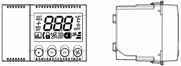

- Terminals
All the terminals of the indoor reader are extractable, of different colour and/or different shape as to avoid mistakes during the connection and/or the replacement of the terminal.
2 poles terminal (black) – SELV
name function
- 12V+/ Power feeding (positive) to be connected with cable cod. CVAVEBUS to the terminal 12V of the CU (connector ARMBus)
- 12V-/ Power feeding (ground reference) to be connected with cable cod. CVAVEBUS to the terminal GND of the room control unit (connector ARMBus). This terminal is also the ground reference for the inputs of the reader.
2 poles (green) – SELV
name function
- Line “A” room bus. It must be connected, with the cable cod. CVAVEBUS, to the corresponding terminal of the control unit (connector ARMBus)
- Line “B” room bus. It must be connected, with the cable cod. CVAVEBUS, to the corresponding terminal of the control unit (connector ARMBus)
10/8 poles Terminal (green) – SELV and LV
name function
- Three statuses input (guest PRESENCE/window CONTACT). When smart internal reader 44..GA30-M is present in the room bus line guest presence contact is not required. If the room is provided with a “key card holder”, to detect the guest presence, the circuit must be realized according to what shown in the installation diagrams section.
- Analog input (INCOMING water probe). Not necessary for the network system (Do NOT use)
- OUT-1 (pole A) Output contact relay (fan-coil valve) – SELV/LV
- OUT-1 (pole B) Output contact relay (fan-coil valve) – SELV/LV
- COM 2-4 (pole B) Common output contact relays 2-4
- OUT-2 (pole A) Output contact relay (command fan-coil speed 1)
- OUT-3 (pole A) Output contact relay (command fan-coil speed 2)
- OUT-4 (pole A) Output contact relay (command fan-coil speed 3)
 The inputs, if not otherwise specified, are designed for the detection of dry contacts status. Outputs contacts are micro gap contacts with maximum current of 5A (resistive load) or 1A (inductive load). The sum of the absorptions of the outputs with common pole (terminals 6, 7 and 8) will not have to exceed 12A (resistive).
- LCD Display
The display of the thermostat, during the normal functioning of the device, provides to the user a few information as below illustrated.
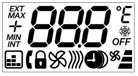
![]() (FROST):
(FROST): ![]() it indicates that the anti-freeze function is active because the temperature detected from the thermostat is lower than the minimum alarm temperature (default= +7°C).
it indicates that the anti-freeze function is active because the temperature detected from the thermostat is lower than the minimum alarm temperature (default= +7°C).
![]()
![]() (FROST): this icon lights (with the previous one) when the anti-freeze function is active.
(FROST): this icon lights (with the previous one) when the anti-freeze function is active.
![]()
![]() (OVERTEMP): it indicates that the overheating function is active because the temperature detected from the thermostat is higher than the maximum alarm temperature (default= +45°C).
(OVERTEMP): it indicates that the overheating function is active because the temperature detected from the thermostat is higher than the maximum alarm temperature (default= +45°C).

 (ARMBUS): it means that the thermostat is polled correctly by the control unit (cod. 53AR01-485 or cod. 53AR02-485).
(SUMMER): indicates that the thermostat is in “summer” mode. If the icon flashes it means that the window is open and that the thermoregulation is stopped (default condition) till the window will be closed.
 (WINTER): indicates that the thermostat is in “winter” mode. If the icon flashes it means that the window is open and that the thermoregulation is stopped (default condition) till the window will be closed.

 (HALF): If the icons are both present, it means that the thermostat is in “intermediate seasons” mode. If the icons flash it means that the window is open and that the thermoregulation is stopped until the window will be closed.
![]() (LOCK): indicates that the keys of the thermostat were locked to avoid modifications to the working parameters. It can be activated both locally and remotely (see paragraph “keypad”) by DH-Sys Client software.
(LOCK): indicates that the keys of the thermostat were locked to avoid modifications to the working parameters. It can be activated both locally and remotely (see paragraph “keypad”) by DH-Sys Client software.
![]()
![]() (ADDRESS): Used only in the configuration menu of the thermostat, parameter 9, it means that the thermostat is showing its address. This is the ARMBus address of the thermostat.
(ADDRESS): Used only in the configuration menu of the thermostat, parameter 9, it means that the thermostat is showing its address. This is the ARMBus address of the thermostat.
(SAVE): it means that the function of “night energy saving” is active. With this function active, the displayed value remain the one set, while the actual set point is changed by a pre-set saving parameter.
![]() (CRONO): it means that the thermostat is in communication with another device provided with a clock (control unit cod.53AR01-485 or cod.53AR02-485) meaning that the management of night energy saving slot is enabled. If this icon flashes it means that the device with clock does not work properly (e.g. battery is low or non-present).
(CRONO): it means that the thermostat is in communication with another device provided with a clock (control unit cod.53AR01-485 or cod.53AR02-485) meaning that the management of night energy saving slot is enabled. If this icon flashes it means that the device with clock does not work properly (e.g. battery is low or non-present).
In this condition (blinking icon) the thermostat keeps active the management of night energy saving using its internal timers to simulate a clock but, after a week from the breakdown (if not restored) or after a thermostat switching off, the management of night energy saving is disabled.
![]() (FANCOIL): Divided in four icons. The little fan means that the fan’s coil valve is open. The vertical symbol (composed by three bars) indicates the speed of the fan coil from one (shorter bar) to three (longer bar).
(FANCOIL): Divided in four icons. The little fan means that the fan’s coil valve is open. The vertical symbol (composed by three bars) indicates the speed of the fan coil from one (shorter bar) to three (longer bar).
![]() (OFF): it means that the thermoregulation was switched-off manually. Even in this condition the antifreeze and over-heating functions remain active; if there are notice of anomalies in the temperature of the room, the water valve is open and the first speed is set.
(OFF): it means that the thermoregulation was switched-off manually. Even in this condition the antifreeze and over-heating functions remain active; if there are notice of anomalies in the temperature of the room, the water valve is open and the first speed is set.
- User interface
The thermostat is provided with a display that can be backlit by pressing a key and turned off automatically after a period of keyboard inactivity of about 5 seconds.
- Keypad
The room thermostat is provided with four frontal keys for the local management of the thermoregulation. The function of every keys is the following:
(OFF): This button enables/disables the thermoregulation.
(INC): Increases the set temperature by 0,1°C steps, within the allowed range (function active only with occupied room)
(DEC): Decreases the set temperature by 0,1°C steps, within the allowed range (function active only with occupied room)
(FAN): This key allows to modify the maximum speed, within the allowed range, that can be used from the fan coil (function active only if the room is occupied)
(LOCK): Keys that, when pressed simultaneously, activate/deactivate the block of the keyboard (padlock icon).
(CONF): keys that, if pressed simultaneously for 5″, allow the access to the configuration menu of the technical parameters of the thermostat.
NETBus: Backbone bus line dedicated to the communication between the control units (cod. 53AR01-485 or cod. 53AR02-485) and the Ethernet interface or gateway cod. AR-NET01.
ARMBus: Room/Common Area bus line dedicated to the communication between the control units (cod. 53AR01-485 or cod. 53AR02-485) and the devices of room/common area (transponder readers and/or thermostats).
AVEBus: Room/Common area automation bus line dedicated to the communication between the control unit (cod. 53AR01-485 or cod. 53AR02-485) and the home automation devices (e.g. 442ABR1).
FEM: acronym; it means the power supply of the loads (EMF = Electro-Motive Force).
Master card: (cod. 44339CHM-M) It is the card in which the univocal code of the plant is stored. It is easily recognizable because is marked with the word master in the serigraphy (see figure below). On the bottom right corner the 4 digits hexadecimal plant code is printed. This card allows every kind of operation in the hotel plant and for this reason must be kept with care in a safe place far from electromagnetic fields, must not be folded or drilled.
User card: (cod. 44339CHU-M) It is the generic card that can be programmed by the system as guest or staff card. This card must be preserved with care far from electromagnetic fields and must not be folded or drilled. The user cards, on demand, can be also provided without serigraphy (completely white) customizable by the hotel (AVE SpA does not offer personalization of the user cards).

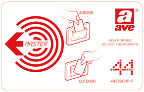
Master card User card
Firmware: Internal program of the devices. All the firmware of the devices can be upgraded through technical software SFW-ALBTEC.
Software: Application program with user interface, like DHSys Client, that must be installed on a computer with Windows® operating system .
Service: Windows® process without user interface, like DHSys-Server, directly activated at the start-up of Windows®.
Electro door lock and electric interface: Electromechanical device that allows the release of the door through an electric impulse.
LAN: defines a Local Area Network where different types of devices are connected to each other through via Ethernet protocol on UTP cables
IP address: Address that identifies in an univocal way a device on a communication network LAN. There are two different types of addressing: 6 bytes (IPv6) or 4 bytes (IPv4); AVE hotel management system works with IPv4 addressing (e.g. 192.168.1.168)
RJ-45: The code RJ-45 (Registered Jack type 45) indicates a type of connector 8P8C (8 Positions – 8 Contacts) suitable for connection of Ethernet devices.
Remote assistance: Technical support provided by AVE or authorized technical assistance centers via internet by means of remote desktop software to be installed on the reception computer.

The wiring for the detection of the alarms coming from the plant shall be made as exemplified in the figure below.
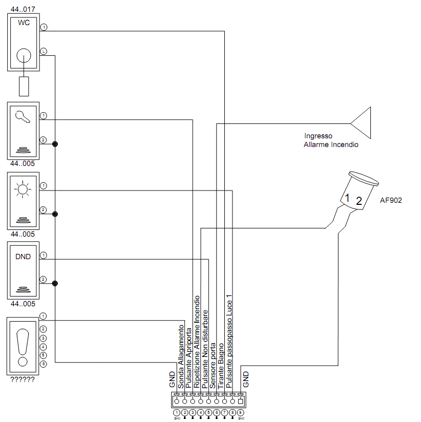
FIG2. Examples of how to do the wiring of the inputs of the control room 53AR01-485
The thermoregulation, managed by the thermostat 44.GA52-T can be inhibited through a contact (Cod. AF902) mounted on the window of the room. Below the wiring diagram of the configuration with window contact.
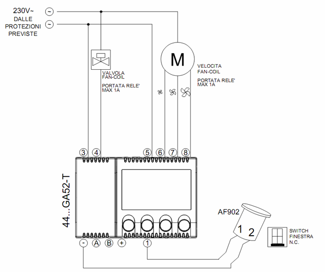
FIG3. Examples of how to do the different wiring related to the temperature control on thermostat 44..GA52-T
A selector activates contact 6, 7 or 8 depending on the desired fan coil speed.
The fan coil valve is opened (contact 4 is closed) when one of the three speeds is selected.
The connection of the room relay that manages the FEM is controlled directly by the room control unit 53AR01-485 and must be connected as shown in the scheme below.The room control unit (through the inputs N°22 and 23), will detect the status of the FEM, communicating to the PC the presence/absence of the FEM inside the room.The software will show the status of the FEM in the room through appropriate icons.
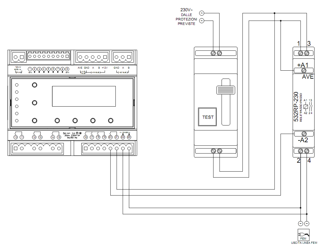
FIG3. Examples of how to wire the room relay on the room control unit 53AR01-485
Below there are the diagrams of the connection for a “type” plant.


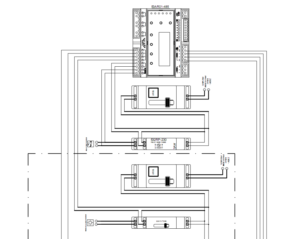
ARMBus line to room devices To the output loads of room devices
| PROBLEMS | POSSIBLE CAUSES | REMEDIAL ACTIONS |
| The computer does not start | Absence 230Vac
UPS off Power cable disconnected |
Verify that the plugs of the PC are connected and that the 230 Vac voltage is present. Verify the correct working of the group UPS (if present). |
| The computer is on but nothing appears on the monitor | Monitor off
Monitor cable disconnected Supply of monitor off |
Verify that the plugs of the monitor are connected, that the 230V ac voltage is present and that the switch is in ON. |
| The application DHSys Client does not connect to the Server | Not started server or not activated license | Open the application Service Configuration and verify that the license was activated. Verify the Server service is active. |
| The application DHSys Client is not running | The Client was disconnected or the Server was closed | Verify that the Server service is active. Verify that the net cable (Ethernet) is connected to the PC, that the net card is working and that a firewall that blocks the communication from and toward the Server service is not installed. |
| The application DHSys Client does not show any room | Plant configuration not performed | Enter the configurator and set up all the parameters of the plant . |
| All the rooms are disconnect (NETBus icon present on all the rooms) | System switched off or disconnectedAR-NET01 off or disconnectedWrong IP Address on the AR-NET01Incorrect firewall rules | Verify that the power supply to the plant and the AR-NET01 is present.Verify that the NETBus cable and the Ethernet cable are connected.Verify that the gateway address is same shown on AR-NET01. Verify that the firewall allows the passage of the data on the IP address AR-NET01 and the address of the Server (info not managed by AVE). |
| Some rooms are disconnected (NETBus icon present) | Room control unit off
NETBus not connected wrong NETBus address |
Verify that, for the rooms that are not online, power supply of the control unit 53AR0..-485 is present and that the cable NETBus is connected. Verify also that the address NETBus shown by the control unit is the correct one. |
| Problems with the programming of new cards | Programmer SCR-ALBM1 not connected/not configured | Verify that the programmer is connected to the computer (USB) and that in the configurator menu it appears “Online”. |
| A card cannot be programmed | Cards programmer not active or blocked
Broken card |
Verify that there are not devices that disturb the correct programmer’s working in proximity of the latter. Disconnect the cable USB from the programmer and connect it by activating it in the configurator of the system (Par 8.4). |
| A valid card does not allow the opening of the door | Card created for another room or wrong date of expiry | Verify that the card was created for the correct room and is valid, verify also that the readers are powered and programmed (green LED blinking). |
| The guest card no longer opens the door | Card expired or inserted in theblacklistNo power supply in the room | Check the expiry date and the validity of the card through the programmer.Verify the presence of power supply to the room control unit. |
| Impossible to modify the temperature setting on the room thermostat | Not enabled cardChanges to the set disabledKeypad locked on the thermostat (symbol lock on) | Verify that the card inserted in the reader allows the modification of the settings of the thermostat (the chambermaid card is not enable to AC management!!!). Verify from software that the modifications to the temperature set are allowed. If appears the symbol of the padlock click on the two external keys of the thermostat simultaneously to unlock it. |
| The thermostat of room/common area is not detected by the software | ID thermostat modified by mistake | Verify that the parameter N° 9 of the thermostat is set up correctly. Otherwise follow the instructions reported in the paragraph 6.5. |
| Air-conditioning does not work inside a room | Thermostat off or energy saving active | Verify that the thermostat is not in the OFF status and, if the sensor is mounted on the windows, that these are closed. |
| The fan coils emit cold air (winter) or warm (summer) | Hydraulic system not regulated or incorrect setting of the season | Verify the hydraulic system is set to the correct season. Verify that the thermostat has been set the correct season. |

This guide is designed to provide information about the installation and configuration of AVE Domina Hotel system. Every efforts has been made to make the information complete and accurate, however, no liability is implied. Some minor variations in the appearance of the program screenshots may exist because of changes made to SFW-ALB.. software after this guide was written.
The information is provided on “as-is” basis. Ave S.p.A. shall have neither liability nor responsibility to any person or entity with respect to any loss or damages in connection with or rising from the information contained in this guide.
For the time and the warranty terms of the single products see www.ave.it and the current commercial catalogue.
The products should be sold in original packaging, otherwise the retailer and/or installer must apply and transmit to the user the installation instructions published on www.ave.it and the current commercial catalogue.
AVE products are installation products. They must be installed by qualified installers according to the current regulations and rules, respecting the instructions of storage, and the best practices of use and installation suggested AVE S.p.A. using appropriate tools and wiring devices.
It is Also required the respect of the general conditions of sale, notes, general warnings, warranties warnings, claims and technical advices for the installer reported on www.ave.it and the current commercial catalogue.
All the data contained in this manual are indicative and not binding, as AVE S.p.A. reserves the right to make changes or variations without any notice.
![]()
- It is suggested to keep a numeration of the addresses that reflects the order of the numeration of the rooms to simplify the maintenance and/or check-up of the plant (ex. for a plant with following rooms: “101 to 108” and “201 to 209” it is suggested to use the addresses between 1.1.01 to 1.1.08 for the first block of rooms and from 1.1.09 to 1.1.12 for the second group (the addresses of the control units are defined in hexadecimal notation). ↑
- To be able to modify the NETBus address of a control unit through the technical software SFW-ALBTEC it is necessary that all the control units connected to the bus have different address. Otherwise it is necessary to disconnect from the bus all the control units but the one which address needs to be modified. ↑
- If Server and Client share the same computer, the characteristics must be extrapolated by choosing the condition best performing: or major in memory or disk space) between the two. ↑
- Time slots must be define inside the day; timetables of slots whose hour of end (End) is lower than that of beginning (Start) are not admitted; a slot with “Start: 21:00 – End: 06.59 “is not valid. It’s however possible to divide a slot such as the one in the previous example in two slots: where the first is “Start: 21:00 – End: 23.59 and the second “Start: 00:00 – End: 06.59”. To activate an output from 21.00 in the evening till 7.00 in the morning it will be sufficient to associate it to both slots. ↑
DOMINA Hotel Network System Realization, Installation and Configuration Technical GUide – DOMINA Hotel Network System Realization, Installation and Configuration Technical GUide –
[xyz-ips snippet=”download-snippet”]