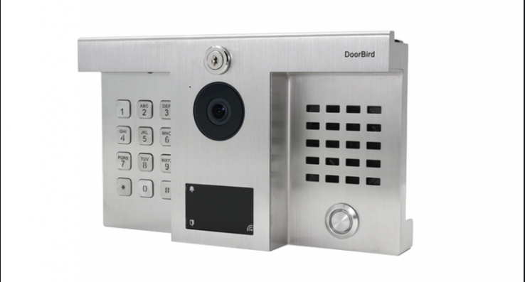
DoorBird B10X BirdGuard
Installation manual
You can always find the most up-to-date version of the installation manual on www.doorbird.com/support
ComponentsContents
- 1x BirdGuard
- 1x 433 MHz RFID Antenna
- 1x 2.4 GHz WiFi Antenna
- 1x Power supply unit (mains adaptor) with four country-specific adaptors
- Several crimp connectors
- 2x Phillips countersunk head screws for the mounting stand, long
- 2x Phillips countersunk head screws for the mounting stand, short
- 2x Dowels
- 1x Mounting stand
- 1x Installation manual
- 1x Quick start guide
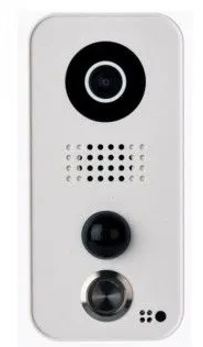
BirdGuard – front
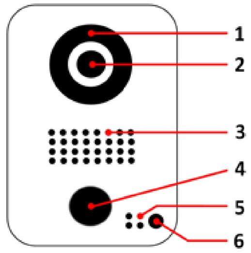
- Night visionExtra bright infra-red LEDs, effective during the hours of darkness (infra-red light invisible to the human eye, 850nm)
- HDTV videoUltra wide-angle hemispheric lens, 180°
- LoudspeakerLarge-sized and speech enhanced broadband speaker
- Motion sensor180° Infrared motion sensor for alarms
- MicrophoneWith active noise cancellation
- Light sensorFor the night-vision mode, also acts as Diagnostic-LED
BirdGuard – back
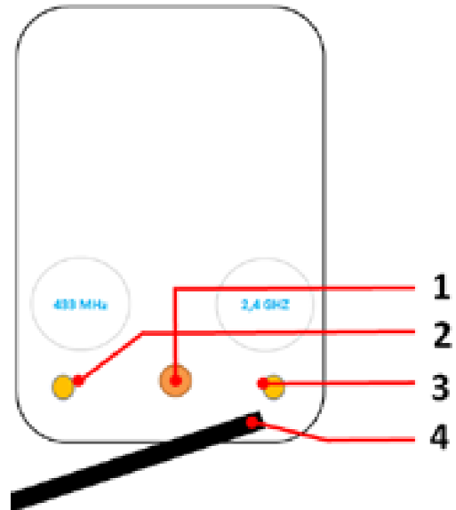
- Mounting stand threadTo connect the mounting stand
- 433 MHz RFID Antenna threadTo connect the external 433MHz RFID antenna
- 2.4 GHz WiFi Antenna threadTo connect the external 2.4GHz WiFi antenna
- Cable harnessTo connect power, network and all external components
VideosNeed help with the installation? Be sure to watch our installation videos which can be found on http://www.doorbird.com/support Each individual step of the installation is clearly documented in the videos.
Installation
All the steps below should be carried out carefully by a competent adult, taking into consideration any applicable safety regulations. Should you have any questions, please contact us or a competent specialist directly. Please ensure that all wires used for the installation are undamaged along their entire length and approved for this type of use.
Network speed and network components
Please ensure that the upload speed of your Internet connection is at least 0.5 Mbps. You can also carry out a speed test at any time via the DoorBird app. The user experience is only as good as your network speed, network stability and quality of your network components, such as your Internet router and WiFi access points or WiFi repeaters. Please also make sure that your network components are no older than two years old, have been manufactured by a well-known manufacturer, and have the latest firmware installed.
Should these requirements not be fulfilled, it may happen, for example that the performance of audio and video is poor or push notifications are delayed or do not arrive on your smartphone or tablet at all.
High-speed Internet (via landline): DSL, cable or optical fibreNetwork: 802.11b/g/n 2.4 GHz or Ethernet, with DHCP
Step 1: Switching off power
Switch off the power to all wires leading to the assembly location, i.e. power supply unit for the BirdGuard etc.
Step 2: Determining the assembly location
The BirdGuard uses an ultra wide-angle hemispheric lens so that even when the person is a minimum distance of 50 cm (19.68 inches) away from the BirdGuard, a low installation height is sufficient. The lens is therefore not mechanically adjustable. The camera lens should be located at an altitude of at least 125 cm (49.22 inches). You may check this prior to the final mounting.The BirdGuard is usually installed outdoors but can also be installed indoors.(Optional) Press the mounting stand against the wall at the desired installation site and mark the boreholes with a pencil. Remove the mounting stand again. Ensure that no cables are to be found in the wall behind the boreholes.
Step 3: Power supply
The BirdGuard can be powered by two simple doorbell wires using the power-supply unit (mains adaptor) supplied with it or via PoE (Power over Ethernet) using a network cable. The BirdGuard can alternatively also be supplied with a DIN-rail power supply unit that you can obtain from us directly.The BirdGuard does not use battery power. The use of a mains power supply permits the transmission and display of on-demand live video at any time.
Power supply using the power-supply unit (mains adaptor)Two insulated wires are required to power the BirdGuard by plugging it into the mains. Only use the power supply unit provided along with the BirdGuard, or a DIN-rail power supply unit that you can obtain from us separately, since this has been specially stabilized electrically and is equipped with an integrated audio interference reduction device. Other power supply units may destroy the BirdGuard or cause poor transmission quality. The warranty automatically expires if you use a different power supply unit. The power supply unit is plugged into a wall socket inside your house.Do not plug the power supply unit into the wall socket yet. Connect the power supply unit inside the house with the crimp connector provided and the two wires that you would like to use to power the device.
Power supply via PoE (as an alternative)To power the BirdGuard via a PoE switch (e.g. D-Link DGS-1008P) or PoE injector (e.g. TP-Link TL-PoE150S) in accordance with the PoE standard IEEE 802.3af Mode A, the four wires bearing the numbers 1, 2, 3 and 6 of a Cat.5 cable or better are to be used. A Cat.5 cable or better must be used as network signals can only be transmitted over completely insulated, shielded and twisted cables. If you use PoE as a source of power, the WiFi interface of the BirdGuard is automatically inactive, and the four wires for PoE then simultaneously form the data link. The BirdGuard won’t start if your PoE Switch or PoE injector does not support the PoE Standard IEEE 802.3af Mode A (see Diagnostic-LED and Diagnostic-Sounds).
- Disconnect the PoE switch or PoE injector from the power grid.
- Place the network cable in the installation site of the BirdGuard.
Do not combine the power supply from the power supply unit (mains adaptor) with the power supply via PoE.
Step 4: Further connections (optional)
If desired, connect additional wires to the installation site of the BirdGuard. The wires or connection options mentioned in this section are optional.
Connecting the unit to a network(Network cable in accordance with the Cat.5 standard or better.)
You can connect the BirdGuard to your existing network via WiFi, or alternatively use a network cable (Ethernet). For reasons of network stability, we principally recommend using a network cable, as WiFi is sensitive to interference (range, house walls acting as shields, reliability of performance, third party WiFi networks, wireless transmitters causing interference in the area, etc.).The BirdGuard can be powered by PoE or using the power supply unit provided.If you use PoE as a source of power, the WiFi interface of the BirdGuard remains inactive.Connect the network cable in the house to your Internet router or to your PoE switch or PoE injector that is connected to your Internet router.
Alarm output (Two insulated wires. )
The BirdGuard has a zero-potential relay contact for connecting external devices such as relays e.g. event triggering and alarm notifications (two wires). There is the possibility of switching on all external devices that work at a maximum power of 1A in the voltage range of up to 24V (AC/DC). The BirdGuard does not provide its own power supply for the external devices. This is provided through the separate power supply of the external devices. You can learn more about the installation of the power supply from the instruction manual or technical specifications of your external devices. Should you have any questions about this, please contact the manufacturer of your external devices. You can find compatible external devices and a sample wiring diagram at www.doorbird.com/support
Alarm input (Two insulated wires. )
The BirdGuard has a zero-potential relay contact for connecting external devices that can toggle between an open and closed circuit, e.g. PIRs, door/window contacts, glass break detectors, etc. (two wires). There is the possibility of connecting all external devices that work at a maximum power of 1A in the voltage range of up to 24V (AC/DC). The BirdGuard does not provide its own power supply for the external devices. This is provided through the separate power supply of the external devices. You can learn more about the installation of the power supply from the instruction manual or technical specifications of your external devices. Should you have any questions about this, please contact the manufacturer of your external devices. You can find compatible external devices and a sample wiring diagram at www.doorbird.com/support
External speaker (Two insulated wires. )
The BirdGuard has a contact for connecting an external speaker, e.g. horn speaker, siren (two wires). We recommend using the combi horn speaker/siren for BirdGuard (incl. amplifier within the BirdGuard) available separately by Bird Home Automation.The following third party external speakers are compatible:
- Power rating: 10 W MAX /8 Ω
- Frequency range: 350-10,000 Hz
- SPL: (1 W/1 m) 100 dB
Warning: Do not connect speakers with other specification or with 110V technology, this will destroy the BirdGuard.
Step 5: (Optional) Dowels
If the exterior wall of the house is not made of wood, you should drill two holes 5 mm in diameter in the wall and then place the dowels provided into the boreholes. If the exterior wall of the house is made of wood, you will usually not require any dowels. There are special dowels for assembling the BirdGuard on an insulating wall, e.g. Fischer insulating dowels. Please check with your insulating material manufacturer regarding which dowels they recommend.
Step 6: (Optional) Attaching the mounting stand
Position the mounting stand against the exterior wall of the house and use the screws provided to position it in the dowels or on the wall.
Step 7: Preparing the wires
Remove about 5 mm of insulation material at the end of the wires that you would like to connect to the BirdGuard.
Step 8: Connecting the wires
It is possible to connect the BirdGuard conveniently and safely via the colour-coded cable harness on the reverse of the BirdGuard. Please use appropriate crimp connectors or terminal strips to connect the supplied cables with your wires. The accompanying crimp connectors are weatherproof and are equipped with heat-shrink tubing which can be sealed after assembly by, for example, carefully using a heat gun.
| Description | Wire |
| Network / Ethernet | RJ 45 Jack |
| Alarm output (zero potential) | Brown |
| Alarm output (zero potential) | White-brown |
| Alarm input (zero potential) | Blue |
| Alarm input (zero potential) | White-blue |
| External speaker, negative pole (-) | Yellow |
| External speaker, positive pole (+) | Pink |
| Power supply, negative pole (-) | Black |
| Power supply, positive pole (+) | Red |
Please take care when connecting the wires. Connecting the wires the wrong way may destroy the BirdGuard.
Step 9: Final assembly
Screw in the 433 MHz RFID Antenna and 2.4 GHz WiFi Antenna into the desired threads on the back of the BirdGuard. Mount the BirdGuard on the mounting stand.
Step 10: Activating the BirdGuard
Switch on the power to the wires leading to the assembly location again. You can see whether you have connected the power supply properly from the Diagnostic LED (it lights up once the power has been connected correctly for up to five minutes and continuously in night-vision mode). The BirdGuard is ready for operation (booting up process, any software updates, etc.) once it has emitted a short diagnosis sound from the integrated loudspeaker. This may last for up to 5 minutes. Should you not hear a beep, please check the power supply. Please also check whether you have used a wall-plug power-supply and not PoE and whether you have connected the positive pole and negative pole to the BirdGuard correctly.
Step 11: Downloading and installing the app
Download the “DoorBird” app by Bird Home Automation onto your mobile device from the Apple app store or Google Play store. You can always find the most up-to-date version of the App manual on www.doorbird.com/supportIf you use WiFi for connecting the BirdGuard to your Internet router, first go to “Settings > WiFi Setup” and follow the instructions.If you have finished the WiFi set-up or have connected the BirdGuard to your Internet router by means of a network cable, go to “Settings > Add device” and click on the QR code icon in the “User” field. Scan the user QR code found on the “Digital Passport” that accompanies the BirdGuard.If you have problems adding the BirdGuard to the App please check if the BirdGuard is online ( www.doorbird.com/checkonline ). If the BirdGuard is not online, please check the WiFi or network cable connection again.
Since Apple uses very high quality microphones, loudspeakers and digital audio components that are perfectly in tune with one another, the voice quality with an iPhone or iPad is usually noticeably better than with an Android smartphone or Android tablet.
Diagnostic-LED
This LED light is only lit up for five minutes after the BirdGuard has been supplied with power (and continuously at night). It lights up as soon as the BirdGuard is supplied with power.
Illuminated: Device is powered
Diagnostic-soundsAfter around two to five minutes, the BirdGuard emits brief diagnostic sounds after it has been connected to the power grid.
- 1x diagnostic sound: The BirdGuard is connected to the Internet.
- 2x diagnostic sounds: The BirdGuard is able to communicate with the router, but cannot access the Internet.
- 3x diagnostic sounds: The BirdGuard has no connection to the network.
LEGAL NOTES
General remarks
- DoorBird is a registered trademark of Bird Home Automation GmbH.
- Apple, the Apple logo, Mac, Mac OS, Macintosh, iPad, Multi-Touch, iOS, iPhone and iPod touch are trademarks of Apple Inc.
- Google, Android and Google Play are trademarks of Google, Inc.
- The Bluetooth® word mark and logos are registered trademarks of Bluetooth SIG, Inc.
- All other company and product names may be trademarks of the respective companies with which they are associated.
- We reserve the right to make changes to our products in the interests of technical advancement. The products shown may also look different from the products supplied based on ongoing enhancement.
- Reproducing or using texts, illustrations and photos from this instruction manual in any media – even if only in the form of excerpts
- shall only be permitted with our express written consent.
- The design of this manual is subject to copyright protection. We do not accept any liability for any errors or any erroneous content or printing errors (even in the case of technical specifications or within graphics and technical sketches).
- Our products are in compliance with all technical guidelines, electrical and telecommunications regulations applicable in Germany, the EU and the USA.
- Our products and also the components contained therein (ICs, software, etc.) may only be used for civilian non-military purposes.
Data privacy and data security
- For maximum security, the device uses the same encryption technologies as are used in online banking. For your security, no port forwarding or DynDNS is used either.
- The data centre location for remote access over the Internet by means of an App is obligatory in the EU if the determined Internet IP-Address location of the device is within the EU. The data centre is operated in line with the most stringent security standards.
- Video, audio and any other surveillance methods can be regulated by laws that vary from country to country. Check the laws in your local region before installing and using this device for surveillance purposes.
If the device is a door-, indoor station or camera:
- In many countries video and voice signal may only be transmitted once a visitor has rung the bell (data privacy, configurable in the App).
- Please carry out the mounting in such a way that the detection range of the camera limits the device exclusively to the immediate entrance area.
- The device may come with a visitor history and motion sensor. You can activate/deactivate this function if required.
If necessary, indicate the presence of the device in a suitable place and in a suitable form.
Please observe any relevant country-specific statutory regulations concerning the use of surveillance components and surveillance cameras applicable at the installation site.
Check with the property owner and your house community if you are allowed to install and use this product. Bird Home Automation GmbH cannot be held responsible for any miss-use or miss-configuration of this product, including the unauthorized opening of a door.
Bird Home Automation cannot be held responsible for damages caused by improper existing installations or improper installation.
Software and operating system’s updates (so-called “firmware updates”) are generally automatically installed on the products of Bird Home Automation GmbH via Internet, if technically possible. Automatic firmware updates keep the products‘ software up to date so that they always work reliably, safely and efficiently. Through further development, features can be added, extended or slightly changed. Major changes or limitations to existing features will generally occur if Bird Home Automation GmbH deems it necessary (e.g. for data protection, data security or stability reasons, or to keep them up to date). When a firmware update is available, Bird Home Automation GmbH‘s servers generally automatically distribute it to all compatible products connected to the Internet or Bird Home Automation GmbH‘s servers. This process is gradual and can take several weeks. As soon as a product receives a firmware update, the system will be installed and will restart by itself. Installed firmware updates cannot be undone. Since the products and software of Bird Home Automation GmbH are not explicitly customer-specific products, a customer cannot deny an automatic update if the product is connected to the Internet or to the Bird Home Automation GmbH’s server.
Instructions for disposal
Do not dispose of the device with regular domestic waste. Electronic equipment must be disposed e.g. at local collection points for waste electronic equipment in compliance with the Waste Elec trical and Electronic Equipment Directive.
PublisherBird Home Automation GmbHUhlandstraße 16510719 BerlinGermanyWeb: www.doorbird.comEmail: [email protected]
It is possible that these manual still contains typographical errors or printing errors.The information in this manual will be checked regularly and corrections will be made in the next version. We accept no liability for errors of a technical or printing nature and their consequences.
![]()
References
[xyz-ips snippet=”download-snippet”]