
DoorBird D20x IP Video Door Station Installation Guide

INSTALLATION MANUAL
Read these instructions carefully before starting to use any components. Keep the manual so you can refer to it at a later date if required. If you hand over the device to other persons for use, please hand over the operating manual as well.You can always find the most up-to-date version of the installation manual on www.doorbird.com/support The installation of the IP Video Door Station to a wall or fence requires professional skills and suitable tools e.g. drilling machine, drill, dowels and if necessary spacers. These are not included. To make things easier we use the term “device” for the product “IP Video Door Station” and “mobile device” for a smartphone or tablet.
Liability
Every care has been taken in the preparation of this document. Please inform Bird Home Automation GmbH of any inaccuracies or omissions. Bird Home Automation GmbH cannot be held responsible for any technical or typographical errors and reserves the right to make changes to the product and manuals without prior notice. Bird Home Automation GmbH makes no warranty of any kind with regard to the content of this document, including, but not limited to, the implied warranties of merchantability and fitness for a particular purpose. Bird Home Automation GmbH shall neither be liable nor responsible for incidental or consequential damages in connection with the furnishing, performance or use of this material. This product is only to be used for its intended purpose.
Equipment Modifications
This equipment must be installed and used in strict accordance with the instructions given in the user documentation. This equipment contains no components that require service by the user. Unauthorized equipment changes or modifications will invalidate all applicable regulatory certifications and approvals.
Symbols used
 Danger: Indicates a hazardous situation which, if not avoided, will result in death or serious injury.
 Warning: Indicates a hazardous situation which, if not avoided, could result in death or serious injury.
 Caution: Indicates a hazardous situation which, if not avoided, could result in minor or moderate injury.
 Notice: Indicates a situation which, if not avoided, could result in damage to property.
 Important: Indicates significant information which is essential for the product to function correctly.
 Note: Indicates useful information which helps in getting the most out of the product.
Hazard information
WARNING
- Mounting, installation and servicing work on electrical devices may only be performed by a qualified eletrician. Failure to observe this regulation could result in the risk of serious damage to health or fatal injury due to electri
- Devices with 110-240 V connection: The device may only be connected to an easily accessible power socket The mains adapter must be pulled out if a hazard occurs.
- For power supply, only use the original plug-in mains adapter delivered with the device or a recommended PoE-Switch/PoE-Injector as specified in this
- Because of electrostatic charging, direct contact with the circuit board can result in destruction of the Direct contact with the circuit board must therefore be avoided at any time.
- Observe the EN 60065 EN 60950 resp. EN 62368 standard.
- Do not use the device if there are signs of damage to the housing, control elements or connecting sockets, for example, or if it demonstrates a If you have any doubts, please have the device checked by an authorized expert.
- Do not open the This voids the warranty of the device. The device does not contain any parts that can be maintained by the user. In the event of an error, please have the device checked by an authorized expert.
- For safety, approval and licensing reasons (CE/FCC/IC ), unauthorized change and/or modification of the device is not permitted.
- The device is not a toy; do not allow children to play with it. Do not leave packaging material lying around. Plastic films/bags, pieces of polystyrene, can be dangerous in the hands of a child.
- Always lay cables in such a way that they do not become a risk to people and domestic
- Voltage is applied to parts within the Do not touch any parts that are not associated with the installation, wiring, or connection. Electric shock could result.
- On devices which are not marked as weather-proof: Keep the device away from water or any other
- Do not install or make any wire terminations while power supply is plugged It can cause eletric shock or damage to the device.
- Before turning on power, make sure wires are not crossed or If not, fire or eletric shock could result.
- High voltage may be present Do not open the device. Electric shock could result
- The device is not of explosion-proof. Do not install or use near gases or flammable Fire or explosion could result.
- Do not install two power supplies in parallel to a single input. Fire or damage to the device could Be sure to connect a single power supply to the device.
- Do not connect any terminal on the device to an AC power Fire or electric shock could result.
- Keep AC cord from being marred or crushed. If the AC cord is fractured, fire or electric shock could
- Do not plug or unplug with wet Electric shock could result.
- Do not put any metal or flammable material into the device. Fire, electric shock, or device trouble could result
- ∙ Existing wiring such as chime wiring, etc. may contain high voltage AC electricity. Damage to the device or electric shock could result. Wiring and installation must be done by a qualified eletrician.
- ∙ When mounting the device on a wall or ceiling, install the device in a convenient location, but not where it could be jarred or bumped. Injury could result.
- ∙ On devices with ground terminals, connect to an earth ground. Otherwise fire or malfunction could result.
- On devices with plastic or real glass, do not put high pressure on the glass. If fractured, injury could result.
- On devices with LCD, if LCD is punctured, do not allow contact with the liquid crystal inside. Injury could result. If necessary, gargle your mouth and clean your eyes or skin with clear water for at least 15 minutes and consult your doctor.
- Do not put anything on the device or cover the device with cloth, silicone, glue, coating, separate covering etc. Fire or device issues could result.
- Do not install the device in any of the following locations. Fire, electric shock, or device trouble could result.– Places under direct sunlight or places near heating equipment that varies in temperature.– Places subject to dust, oil, chemicals, hydrogen sulfide (hot spring).– Places subject to moisture and humidity extremes, such as bathrooms, cellars, greenhouses, etc.– Places where the temperature is very low, such as inside a refrigerated area or in front of an air conditioner.– Places subject to steam or smoke (e.g. near heating or cooking surfaces).– Where noise generating devices such as dimmer switches or inverter electrical appliances are closeby.– Locations subject to frequent vibration or impact.
- On devices with intercom, be sure to perform a call test with low audio volume on both intercom devices. A sudden call etc. may arrive causing for example damage to your ear.
- If the device does not operate properly, unplug the power supply.
- All devices which are not marked as weather-proof are designed for indoor use only. Do not use outdoor.
- On devices which are marked weather-proof: Do not spray with high-pressure water. Device issues could result.
- We do not assume any liability for damage to property or personal injury caused by improper use or the failure to observe the hazard information. In such cases, any claim under warranty ceases. For consequential damages, we assume no liability!
Safety instructions
- The device shall be used in compliance with local laws and
- Store the device in a dry and ventilated
- Avoid exposing the device to shocks or heavy
- Do not install the device on unstable brackets, surfaces or walls. Make sure the material is strong enough to support the weight of the
- Use only applicable tools when installing the Using excessive force with tools could cause damage to the device.
- Do not use chemicals, caustic agents, or aerosol
- Use a clean dry cloth for
- Use only accessories that comply with technical specification of the These can be provided by Bird Home Automation GmbH.
- Use only spare parts provided by or recommended by Bird Home Automation
- Do not attempt to repair the device by Contact Bird Home Automation GmbH for service matters.
- Keep the device more than 1 m (3.3′) away from microwave, radio, TV, wireless router and any other wireless
- On devices with intercom or built-in speaker or built-in microphone or signal transmission functions, keep the wires more than 30 cm (12”) away from AC 100-240 V wiring. AC induced noise and/or device malfunction could
- Install the device in an area that will be accessible for future inspections, repairs and
- If the device is used close to a cellular phone, the device may
- The device can be damaged if Handle with care.
- The device turns inoperative during power
- On devices with intercom or built-in speaker or built-in microphone, in areas where cellular or Radio / TV broadcasting station antennas are closeby, the device may be affected by radio frequency
- On devices with LCD screen, it must be noted in advance that the LCD panel, though manufactured with very high precision techniques, inevitably will have a very small portion of its picture elements always lit or not lit at This is not considered a device malfunction.
- On devices with intercom, due to the environmental sound around the device, it may hinder smooth communication, but this is not a
- On devices with Username/Password, the Username/Password to access the device is the customer’s Make sure to use password that cannot be easily guessed by a third party.
We recommend that you change the Password on a regular basis. We will, under no circumstances, be liable for damage that occurs due to failures in power supply, network equipment or terminal devices; failures due to Internet providers and cellular network providers; failures such as disconnected lines and other losses in communication, which makes it impossible to provide this service as well as in any way delay this service due to any other causes outside of our responsibility; or if an error or missing data occurs during transmission
Transportation
When transporting the device, use the original packaging or equivalent to prevent damage to the device
Warranty Information
For information about the device warranty, see www.doorbird.com/warranty
COMPONENTS
Contents
- 1x DoorBird IP Video Door Station
- 1x Mounting housing / Mounting plate
- 1x Power supply unit (mains adaptor) with four country-specific adaptors
- External 2,4 GHz WiFi antenna
- 1x External 433 MHz RFID antenna
- 2x Antenna extension cable
- 1x Screw package with small parts and crimp connectors
- 1x Installation manual
- 1x Quick start guide
Video door station

- Night vision Extra bright infra-red LEDs, effective during the hours of darkness (infra-red light invisible to the human eye, 850 nm)
- HDTV video Ultra wide-angle hemispheric lens, 180°
- Loudspeaker Large-sized and speech enhanced broadband speaker
- Motion sensor 180° Infrared motion sensor for alarms
- Stainless-Steel Button With illuminated LED ring (at night), also acts as Diagnostic-LED
- Light sensor For the night-vision mode
- Microphone With active noise cancellation
- Nameplate Illuminated (at night)
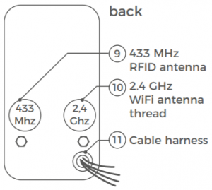
- 433 MHz RFID antenna thread To connect the external 433 MHz RFID antenna
- 2.4 GHz WiFi antenna thread To connect the external 2.4 GHz WiFi antenna
- Cable harness For connection to the power supply, network etc.
VIDEOS
Need help with the installation? Be sure to watch our installation videos which can be found on http://www.doorbird.com/supportEach individual step of the installation is clearly documented in the videos.
INSTALLATION
All steps below should be carried out carefully by a competent adult, taking into consideration any applicable safety regulations. Should you have any questions, please contact us or a competent specialist directly. Please ensure that all wires used for the installation are undamaged along their entire length and approved for this type of use.
Network speed and network components
Please ensure that the upload speed of your Internet connection is at least 0.5 Mbps. You can also carry out a speed test at any time via the DoorBird app. The user experience is only as good as your network speed, network sta- bility and quality of your network components, such as your Internet router and WiFi access points or WiFi repeaters. Please also make sure that your net- work components are no older than two years old, have been manufactured by a well-known manufacturer, and have the latest firmware installed.Should these requirements not be fulfilled, it may happen, for example that the performance of audio and video is poor or push notifications are delayed or do not arrive on your smartphone or tablet at all. High-speed Internet (via landline): DSL, cable or optical fibre Network: 802.11b/g/n 2.4 GHz or Ethernet, with DHCP
STEP 1: SWITCHING OFF POWER
Switch off the power to all wires leading to the assembly location, i.e. the door chime, electric door opener, power supply unit for the video door station etc..
STEP 2: DISMANTLING THE EXISTING DOORBELL
Should there already be a doorbell on the exterior wall of the house, please dismantle it.
STEP 3: DETERMINING THE ASSEMBLY LOCATION
The video door station uses an ultra wide-angle hemispheric lens so that even when the person is a minimum distance of 50 cm (19.68 inches) away from the video door station, a low installation height is sufficient. The lens is therefore not mechanically adjustable. The camera lens should be located at an altitude of at least 145 cm (57 inches). You may check this prior to the final mounting. Press the mounting plate against the wall at the desired installation site and mark the boreholes with a pencil. Remove the mounting plate again. Ensure that no cables are to be found in the wall behind the boreholes When choosing the assembly location, consider the lighting conditions. Avoid direct sunlight, direct backlight and reflective surfaces
Do not expose the device to direct sunlight. The housing temperature can exceed the maximum allowed temperature limit. This can result in damage of electric and mechanic components of the device and injuries especially when touching exterior parts of the device. White and bright silver-colored front plates absorb less sunlight than dark ones.
An image sensor must not be exposed to direct sunlight for an extended period of time. Direct sunlight will “blind” the camera and may permanently bleach the small color filters on the image sensor chip.
Any defects caused by direct sunlight is not covered by warranty.
STEP 4: POWER SUPPLY
The video door station can be powered by two simple doorbell wires using the power-supply unit (mains adaptor) supplied with it or via PoE (Power over Ethernet) using a network cable. The video door station can alternatively also be supplied with a DIN-rail power supply unit that you can obtain from us directly.The video door station does not use battery power. The use of a mains power supply permits the transmission and display of on-demand live video at any time and not only if a visitor has pressed the doorbell.
Power supply using the power-supply unit (mains adaptor)
Two insulated wires are required to power the video door station by plugging it into the mains. These wires are normally already there and are freely accessible once you have removed the previous doorbell. Only use the power supply unit provided along with the video door station, or a DIN-rail power supply unit that you can obtain from us separately, since this has been spe- cially stabilized electrically and is equipped with an integrated audio interfe- rence reduction device. Other power supply units may destroy the video door station or cause poor transmission quality. The warranty automatically expi- res if you use a different power supply unit. The power supply unit is plugged into a wall socket inside your house, usually where the two wires from your previous doorbell come out of the wall in the interior of the house.Do not plug the power supply unit into the wall socket yet. Connect the po- wer supply unit inside the house with the crimp connector provided and the two wires that you would like to use to power the device.
Power supply via PoE (as an alternative)
To power the video door station via a PoE switch (e.g. D-Link DGS-1008P) or PoE injector (e.g. TP-Link TL-PoE150S) in accordance with the PoE standard IEEE 802.3af Mode A, the four wires bearing the numbers 1, 2, 3 and 6 of a Cat.5 cable or better are to be used. A Cat.5 cable or better must be used as network signals can only be transmitted over completely insulated, shielded and twisted cables. If you use PoE as a source of power, the WiFi interface of the video door station is automatically inactive, and the four wires for PoE then simultaneously form the data link. The video door station won’t start if your PoE Switch or PoE injector does not support the PoE Standard IEEE 802.3af Mode A (see Diagnostic-LED and Diagnostic-Sounds).
- Disconnect the PoE switch or PoE injector from the power
- Place the network cable in the installation site of the video door
Do not combine the power supply from the power supply unit (mains adaptor) with the power supply via PoE.
STEP 5: FURTHER CONNECTIONS (OPTIONAL)
If desired, connect additional wires to the installation site of the video door station. The wires or connection options mentioned in this section are optional.
Connecting the unit to a network
You can connect the video door station to your existing network via WiFi, or alternatively use a network cable (Ethernet). For reasons of network stability, we principally recommend using a network cable, as WiFi is sensitive to interference (range, house walls acting as shields, relia- bility of performance, third party WiFi networks, wireless transmitters causing interference in the area, etc.). The video door station can be powered by PoE or using the power supply unit provided. If you use PoE as a source of power, the WiFi interface of the video door station remains inactive.Use only four wires (1, 2, 3 and 6) of a network cable that meets the Cat.5 standard or a better one. The other four wires of the network cable (4, 5, 7 and 8) are not required. Connect the network cable in the house to your Internet router or to your PoE switch or PoE injector that is connected to your Internet router.
Be sure to use four insulated, shielded and twisted wires of a network cable in accordance with the Cat.5 standard or better.

Electric door openers
The video door station has a zero-potential relay contact for a standardised electric door, gate or garage opener (two wires). There is the possibility of switching on all electric door openers that work at a maximum power of 1 A in the voltage range of up to 24 V (AC/DC). The video door station does not provide its own power supply for the electric door opener. This is provided through the separate power supply of the electric door opener. You can learn more about the installation of the power supply from the instruction manual or technical specifications of your door opener. Should you have any questions about this, please contact the manufacturer of your door opener. You can find compatible electric door opener and a sample wiring diagram at www.doorbird.com/support
Two insulated wires.
Conventional electric door chime
If someone rings your video door station, you will imme- diately receive a push notification with sound/vibration on your smartphone or tablet. In addition the video door station comes with a zero-potential relay contact for connecting a conventional electric door chime inside the building. The relay contact can be used to activate the separate operating voltage of the door chime or the door chime via its trigger input. If the operating voltage of the door chime is activated, it should not be greater than 24 V (AC/DC). The power consumption should not exceed 1A. The video door station does not provide its own power supply for the door chime. This is provided through the separate power supply of your conventional door chime. Should you have any questions, please con- tact the manufacturer of your door chime. You can find compatible door chimes and a sample wiring diagram at www.doorbird.com/supportTwo insulated wires
If an electric door opener is connected to the video door station, the door opener can be opened by App and also be directly controlled via a zero-potential button to be found in the interior of the building, i.e. a door opening button. In addition, the door opener button is to be connected to the connection terminal provided. Please make sure to add no extra voltage on that contact. You can find compatible door opener buttons and a sample wiring diagram on www.doorbird.com/support
Two insulated wires
STEP 6: (OPTIONAL) ATTACHING THE MOUNTING HOUSING
Position the mounting housing against the exterior wall of the house and use the screws provided to position it in the dowels or on the wall. Feed the wires that you want to connect to the Video Door Station through the hole provided in the mounting housing. Attach the mounting housing. The attachment of the mounting housing for the Video Door Station series D20x is individually adapted to the assembly location. If necessary, call a professional for help
Most common ways to attach the mounting housing:
| MODEL | ATTACHMENT METHOD |
| D201 | With screws |
| D202 | With screws and / or grout |
| D203 | With screws and / or grout. You have to drill holes in the mounting housing if necessary |
| D204 | With screws and / or grout. You have to drill holes in the mounting housing if necessary |
| D205 | Depends on the environment / integration |
STEP 7: PREPARING THE WIRES
Remove about 5 mm of insulation material at the end of the wires that you would like to connect to the Video Door Station.
STEP 8: CONNECTING THE WIRES
It is possible to connect the Video Door Station conveniently and safely via the colour-coded cable harness on the reverse of the Video Door Station. Please use appropriate crimp connectors or terminal strips to connect the supplied cables with your wires. The accompanying crimp connectors are weatherproof and are equipped with heat-shrink tubing which can be sealed after assembly by, for example, carefully using a heat gun.
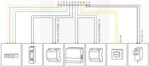
| CONNECTOR | DESCRIPTION | WIRE |
| T+ | White and orange network cable wire (Number 1, Transmit Data +) | white-orange |
| T- | Orange network cable wire (Number 2, Transmit Data -) | orange |
| R+ | White and green network cable wire (Number 3, Receive Data +) | white-green |
| R- | Green network cable wire (Number 6, Receive Data -) | green |
| O1 | Electric door opener (zero potential) | purple |
| O2 | Electric door opener (zero potential) | purple |
| C1 | Electric door chime (zero potential) | blue |
| C2 | Electric door chime (zero potential) | blue |
| B1 | Door-opening button | yellow |
| B2 | Door-opening button | yellow |
| V- | Power supply, negative pole (-) | black |
| V+ | Power supply, positive pole (+) | red |
Please take care when connecting the wires. Connecting the wires the wrong way may destroy the Video Door Station.
STEP 9: ANTENNAS
Screw the external 2.4 GHz WiFi antenna using an Antenna extension cable to the designated position on the back of the Video Door Station. Screw also the external 433 MHz RFID antenna using an Antenna extension cable to the designated position on the back of the Video Door Station. We recommend to feed the antennas out of the housing for better reception and transmission power, because it is made of metal (shields). If you don’t want to use WiFi or RFID at all, you don’t have to screw the respective antenna to the designa- ted position.
STEP 10: FINAL ASSEMBLY
Applies only to DoorBird Video Door Station D201 and D202: Screw the front panel with the attached Video Door Station to the mounting housing with the safety screws and the appropriate tool. Applies only to DoorBird Video Door Station D203 and D204: Mount the Video Door Station with appro- priate screws/dowels on the wall/fence. D205: Depends on the environment / integration. If necessary, call a professional for help.
STEP 11: ACTIVATING THE VIDEO DOOR STATION
Switch on the power to the wires leading to the assembly location again.
You can see whether you have connected the power supply properly from the Diagnostic LED (it lights up once the power has been connected correctly
for up to five minutes and continuously in night-vision mode). The video door station is ready for operation (booting up process, any software updates, etc.) once it has emitted a short diagnosis sound from the integrated loudspeaker. This may last for up to 5 minutes. Should you not hear a beep, please check the power supply. Please also check whether you have used a wall-plug power-supply and not PoE and whether you have connected the positive pole and negative pole to the video door station correctly.
STEP 12: DOWNLOADING AND INSTALLING THE APP
Download the „DoorBird“ app by Bird Home Automation onto your mobile device from the Apple app store or Google Play store. You can always find the most up-to-date version of the App manual on www.doorbird.com/support
If you use WiFi for connecting the video door station to your Internet router, first go to „Settings > WiFi Setup“ and follow the instructions.If you have finished the WiFi set-up or have connected the video door station to your Internet router by means of a network cable, go to „Settings > Add device“ and click on the QR code icon in the „User“ field. Scan the user QR code found on the „Digital Passport“ that accompanies the video door station.If you have problems adding the video door station to the App please checkif the video door station is online ( www.doorbird.com/checkonline ).If the video door station is not online, please check the WiFi or network cable connection again.Since Apple uses very high quality microphones, loudspeakers and digital audio components that are perfectly in tune with one another, the voice quality with an iPhone or iPad is usually noticeably better than with an Android smartphone or Android tablet.
DIAGNOSTIC-LED
This LED light is only lit up for five minutes after the Video Door Station has been supplied with power (and continuously at night). It lights up as soon as the Video Door Station is supplied with power.
- Illuminated: Device is powered
DIAGNOSTIC-SOUNDS
After around two to five minutes, the video door station emits brief diagno- stic sounds after it has been connected to the power grid.
- 1x diagnostic sound: The video door station is connected to the Internet
- 2x diagnostic sounds: The video door station is able to communicate with the router, but cannot access the Internet
- 3x diagnostic sounds: The video door station has no connection to the network
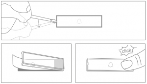
CHANGING THE LABELING ON THE NAME PLATE
LEGAL NOTES
General remarks
- DoorBird is a registered trademark of Bird Home Automation
- Apple, the Apple logo, Mac, Mac OS, Macintosh, iPad, Multi-Touch, iOS, iPhone and iPod touch are trademarks of Apple
- Google, Android and Google Play are trademarks of Google, Inc.
- The Bluetooth® word mark and logos are registered trademarks of Bluetooth SIG,
- All other company and product names may be trademarks of the respective companies with which they are
- We reserve the right to make changes to our products in the interests of technical The products shown may also look different from the products supplied based on ongoing enhancement.
- Reproducing or using texts, illustrations and photos from this instruction manual in any media – even if only in the form of excerpts – shall only be permitted with our express written consent.
- The design of this manual is subject to copyright We do not accept any liability for any errors or any erroneous content or printing errors (even in the case of technical specifications or within graphics and technical sketches).
- Our products are in compliance with all technical guidelines, electrical and telecommunications regulations applicable in Germany, the EU and the USA.
- Our products and also the components contained therein (ICs, software, ) may only be used for civilian non-military purposes.
Data privacy and data security
- For maximum security, the device uses the same encryption technologies as are used in online banking. For your security, no port forwarding or DynDNS is used either.
- The data centre location for remote access over the Internet by means of an App is obligatory in the EU if the determined Internet IP-Address location of the device is within the The data centre is operated in line with the most stringent security standards.
- Video, audio and any other surveillance methods can be regulated by laws that vary from country to country. Check the laws in your local region before installing and using this device for surveillance purposes.
If the device is a door-, indoor station or camera:
- In many countries video and voice signal may only be transmitted once a visitor has rung the bell (data privacy, configurable in the App).
- Please carry out the mounting in such a way that the detection range of the camera limits the device exclusively to the immediate entrance
- The device may come with a visitor history and motion sensor. You can activate/deactivate this function if
If necessary, indicate the presence of the device in a suitable place and in a suitable form. Please observe any relevant country-specific statutory regulations concerning the use of surveillance components and surveillance cameras applicable at the installation site.Check with the property owner and your house community if you are allowed to install and use this product. Bird Home Automation GmbH cannot be held responsible for any miss-use or miss-configuration of this product, including the unauthorized opening of a door. Bird Home Automation cannot be held responsible for damages caused by improper existing installations or improper installation. Software and operating system’s updates (so-called “firmware updates”) are generally automatically installed on the products of Bird Home Automation GmbH via Internet, if technically possible. Automatic firmware updates keep the products‘ software up to date so that they always work reliably, safely and efficiently. Through further development, features can be added, extended or slightly changed. Major changes or limitations to existing features will generally occur if Bird Home Automation GmbH deems it necessary (e.g. for data protection, data security or stability reasons, or to keep them up to date). When a firmware update is available, Bird Home Automation GmbH‘s servers generally automatically distribute it to all compatible products connected to the Internet or Bird Home Automation GmbH‘s servers. This process is gradual and can take several weeks. As soon as a product receives a firmware update, the system will be installed and will restart by itself. Installed firmware updates cannot be undone. Since the products and software of Bird Home Automation GmbH are not explicitly customer specific products, a customer cannot deny an automatic update if the product is connected to the Internet or to the Bird Home Automation GmbH’s server.
Instructions for disposal
Do not dispose of the device with regular domestic waste. Electronic equipment must be disposed e.g. at local collection points for waste electronic equipment in compliance with the Waste Electrical and Electronic Equipment Directive.
Publisher
Bird Home Automation GmbH Uhlandstraße 165
10719 Berlin Germany
Web: www.doorbird.com Email: [email protected]
It is possible that these manual still contains typographical errors or printing errors.The information in this manual will be checked regularly and corrections will be made in the next version. We accept no liability for errors of a technical or printing nature and their consequences.
Read More About This Manual & Download PDF:
References
[xyz-ips snippet=”download-snippet”]