
OPERATING ANDINSTALLATION MANUAL
HEATING FLANGE WITH CERAMIC ELEMENTSTPK 150 – 8 / 2,2 kWTPK 168 – 8 / 2,2 kWTPK 210 – 12 / 2,2 kWTPK 210 – 12 / 3-6 kWTPK 210 – 12 / 5-9 kWTPK 210 – 12 / 12 kW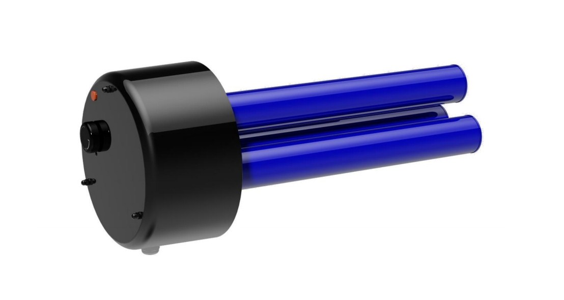
![]()
CAREFULLY READ THIS MANUAL BEFORE INSTALLING THE WATER HEATER!
Dear customer,
The Works Cooperative of Dražice – Machine Plant, Ltd., would like to thank you for your decision to use a product of our brand.
The product is not intended to be controlled bya) people (including children) with reduced physical, sensual or mental capacities, orb) people with insufficient knowledge and experiences unless supervised by responsible person, or unless properly instructed by such responsible person.The manufacturer reserves the right for engineering modification of the product. The product is designed for permanent contact with drinkable water.It is recommended to use the product in indoor environment with air temperatures from +2 °C to +45 °C and a relative humidity up to 80 %.Product’s reliability and safety is proven by tests implemented by the Engineering Test Institute in Brno.
Made in the Czech Republic.
Meaning of pictograms used in the Manual
 Important information for heater users.
 Abiding by the recommendations of the manufacturer serves to ensure trouble-free operation and the long service life of the product.
 Caution! Important notice to be observed
1 USE
The TPK series heating flanges are designed as main heating devices for electric heaters from DZD type OKCE S as secondary heating devices for OKC NTR(R)/BP, OKC NTR/HP, OKC NTRR/HP/SOL and accumulation tanks of heating, solar and other systems. Heating flange can be used to heat water also in other facilities provided the installation instructions are achieved. With their construction, they are only designed to heat water up to tank pressure of 1 MPa and temperature of 110 °C.
2 DESCRIPTION
Heating flange is an enameled weld of flange and wells. TPK is equipped with a thermostat and a safety fuse with external control and relevant electric installation. The electric wiring is placed underneath a plastic cover.
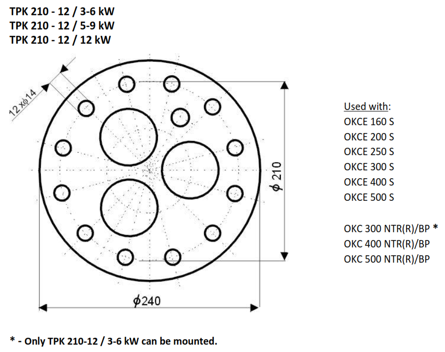
TPK 150 – 8TPK 168 – 8TPK 210 – 12

TPK 210 – 12
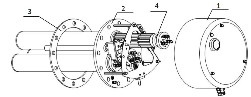
1. Plastic electric installation guard2. Heating flange3. Gasket4. Ceramic element
3 FUNCTION
After setting the heating temperature between 5 °C – 74 °C, the in-built PTK is unmanned. The thermostat activates heating elements and after reaching the set temperature the thermostat turns off. The operation of the element is indicated with lit-up control glow lamps. If the thermostat fails, the safety fuse deactivates the power supply if 95 °C is reached. The safety fuse is non-reversible, i.e. that it has to be turned on once the failure is removed.
4 ADVANTAGES OF USE
– Heating flange with elements in steel wells is more resistant in waters rich in calcium, with increased formation of scale.– Placing the elements in steel wells increases the lifetime of the heater tank. Electric potential is better kept at corresponding values.– If the element fails, it can be replaced without draining water from the tank.
5 ENERGY SAVING
Low water temperature in the heater proves to be especially economic. Therefore, the temperature should be set to be adequate for intended hot water consumption, not higher. This helps to save electricity and prevents lime sediment occurrence.
6 OPERATION AND TEMPERATURE SETTING
The temperature of water in the heater can be adjusted as needed by the thermostat, either continuously or in three steps as indicated. This allows energetically economic operation. To set the temperature, 3 main marked symbols are used:
- * accumulator freezing protection
- Approx. 60 °C, hot water – to prevent scalding, setting this degree is recommended as it is the economic operation with minimum energy loss and minimum scale occurrence
- maximum, approx. 74 °C, hot water
Attention: When the thermostat wheel is in the utmost left position, this is not the zero position nor is the heating turned off.During day mode operation, the thermostat should not be set to temperatures above 60 °C.
7 OPERATION PRECONDITIONS
The connection of an electric flange unit must follow the data on the plate (operation pressure, heating time, electric voltage). Connecting to the electrics must follow the scheme on the inside of the protective cover for the particular flange types.Aside from the electric regulations the conditions of local distribution and water supply plants, as well as assembly and operation conditions, must be followed. If the water is really hard, we recommend installation of water treatment filters preventing the scale occurrence.These heating elements are suitable for enameled accumulators, double casing tanks, or accumulators coated with either plastic or zinc; they are also suitable for ribbed exchangers. Combination with chromium-nickel tanks is problematic, and therefore not recommended. All elements are suitable for heating drinkable and heating water with operating pressure within 10 bar.
8 ASSEMBLY AND SAFETY INSTRUCTIONS
8.1 GENERAL INSTRUCTIONS
During operation, both the heating element and the anode rod must be under water. Necessary thermal flow of heated water must not be prevented. The heating unit is equipped with a safety fuse preventing further water heating at the maximum temperature of 95 °C approximately. It is therefore necessary to select suitable connecting components (pipelines, safety valve combination) that, in case of thermostat defect, resist the maximum temperature of 110 °C.Both the assembly and installation must be implemented by authorized people only.
Position of installation of TPK series elements
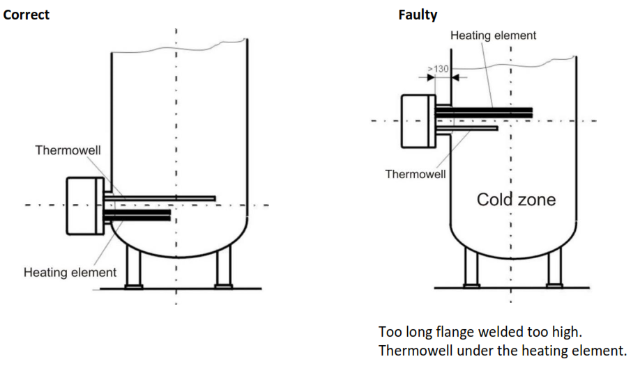
The flanged rim must not exceed 130 mm, so that the temperature sensor and the element reach into the tank deep enough. Correct position of a built-in element assures even heating of the tank contents. In front of the flange, a free space depending on the length of the element must be left for the assembly. Scale occurrence lowers functionality; it is, therefore, necessary, especially with hard water, to take the following measures: Select proper temperature setting; install a device reducing water hardness; regular removal of heater scale.
8.2 TPK – DIVISION


8.3 HEATING UNIT ASSEMBLY
Aside from the installation regulations, the conditions of connection resulting from local distribution and water supply plants must be followed:
- Remove protective cover (position 1)
- The variant TPK 168-8 requires to fit sealing on the screws, place the heating flange (position 2) and screw on the screws in the flange above the tanks (torque 15 Nm). The variant TPK 210-12 requires to screw 3 auxiliary threaded bars M12x50 evenly on the periphery into 3 threaded holes. Fit on the sealing and place the heating flange (position 2). Then screw the remaining 9 screws M12x30 and fasten it with a cross (torque 15 Nm). Then unscrew the threaded bars and replace them with the remaining 3 screws M12x30 and fasten it (torque 15 Nm).
- Carry out electric connection following the scheme (see point 8.5). Warning – do not forget to connect the guard wire. With flanges with selectable output, interconnect the terminal boards to the required output.
- Put on the protective guard and thermostat control. Cover the gap between the heater shell and flange guard with the attached profile.
- Commissioning is possible solely when the tank is filled with water.
Heating element assembly and its initial operation can only be implemented by an expert, who takes responsibility for proper implementation and equipment.
The space in front of the electrical heating unit equal to the installation length + 50 mm must be left free for installation, etc.
8.4 ELECTRICAL CONNECTION
The electrical connection must be implemented based on the attached scheme. The scheme is placed inside the plastic cover of the heating flange and it relates to the specific type!The network voltage must be respected!All metal parts of the accumulator must meet relevant protective regulations.
The main must have multipole switch with at least 3 mm contact spacing. All switches must be connected to circuit breakers. The supply cable must be supplied into the area of connection via a sealing bushing and secured from shifting, wringing, and tearing out by a clamp.Wiring schemeHeating unit 2.2 kWCaution! The factory connection must not be changed!

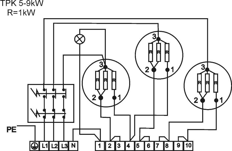
Heating unit 3-6 kW und 5-9 kW
Caution! The factory connection must not be changed!
Heating unit 3-6 kW enables 4 connection types and heating units 5-9 kW 3 types of connection according to the required output considering the heating tank and the option of electricity network onsite.
To achieve the chosen performance of the heating unit, connect the inlet conductor to L1, L2, L3, and N terminal board and interconnect the terminals on the terminal board 1-10 according to the below schemes:
Wiring scheme

Wiring scheme

Heating unit 12 kW
Caution! The factory connection must not be changed!

8.5 PUTTING INTO OPERATION
Before electric part connection, the accumulator must be filled with water. During the rating, water must drip off the safety valve.
Attention: Both the hot water outlet pipe and safety armature parts may be hot.
After heating, the set temperature of consumed water should roughly correspond with temperature shown on the thermometer.
9 INSPECTION, CARE, MAINTENANCE
High calcium content water requires the removal of both scale and calcium sediments after one or two years, implemented by an expert worker. Cleaning may be implemented through the flange opening; a new seal must be used during assembly.Specially enameled accumulator containers must not get in contact with scale solvents or a lime pump. Eventually, the container must be thoroughly rinsed; its re-heating must follow the method of initial operation.During the maintenance, protective connection of all metal (conductive) parts of the heater must not be damaged or removed. Neither mechanical means causing abrasion nor paint thinners (nitro, tricholor, etc.) can be used for cleaning. It is best to use a wet cloth with couple drops of a neutral cleaning preparation.
10 MALFUNCTIONS
Do not attempt to repair the failure yourselves. Seek either expert or service help. It does not take much for an expert to remove the defect. When making a repair appointment, report the type and serial number you find on the performance plate of your heating element.

Note: Every heating element is made of two or more coils connected in parallel. The element works but on lower output.
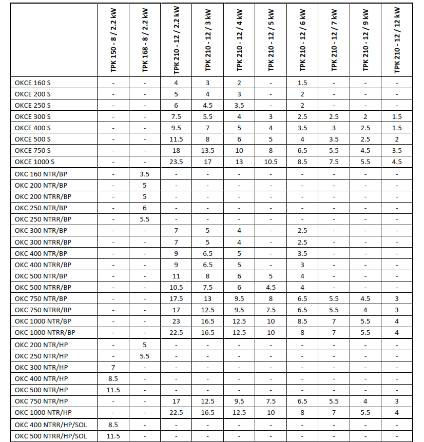
11 TECHNICAL DATA
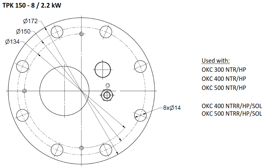
Screw spacing circle diameter 150 mm – TPK 150 – 8 / 2.2 kWScrew spacing circle diameter 168 mm – TPK 168 – 8 / 2.2 kWScrew spacing circle diameter 210 mm – TPK 210 – 12 / 2.2 kW; TPK 210 – 12 / 3-6 kW, TPK 210 – 12 / 5-9 kW; TPK 210 – 12/ 12 kW
Range of thermostat settings: Continuous setting from 5 °C by approx. 74 °C. The gasket is attached.

Time of heating the heating flange
12 IMPORTANT NOTICES
The following cases do not entitle the Customer to exercise the right from defective performance:
– damage caused by dry operation– damage caused by lime scale deposits– damage caused by chemical or electrochemical influences– damage due to incorrect voltage, lightning strike, or voltage surges
12.1 SPARE PARTS LIST
– Housing cover– Gasket– Ceramic element 2.2 kW for single-phase connection– Ceramic element 3 kW for single-phase connection– Ceramic element 2 kW, 3 kW and 4 kW for three-phase connection– Thermostat– Control light– Thermostat knob– Set of bolts
More on https://www.dzd.cz/en
13 DISPOSAL OF PACKAGING MATERIAL AND NON-FUNCTIONING PRODUCT
A service fee for providing return and recovery of packaging material has been paid for the packaging in which the product was delivered. The service fee was paid pursuant to Act No 477/2001 Coll., as amended, at EKO-KOM a.s. The client number of the company is F06020274. Take the water tank packages to a waste disposal place determined by the municipality. When the operation terminates, disassemble, and transport the discarded and unserviceable heater to a waste recycling center (collecting yard), or contact the manufacturer.
Dražice Heating Flange With Ceramic Elements TPK 150-8, TPK 168-8, TPK 210-12 User Manual – Dražice Heating Flange With Ceramic Elements TPK 150-8, TPK 168-8, TPK 210-12 User Manual –
[xyz-ips snippet=”download-snippet”]