Owner’s Manual
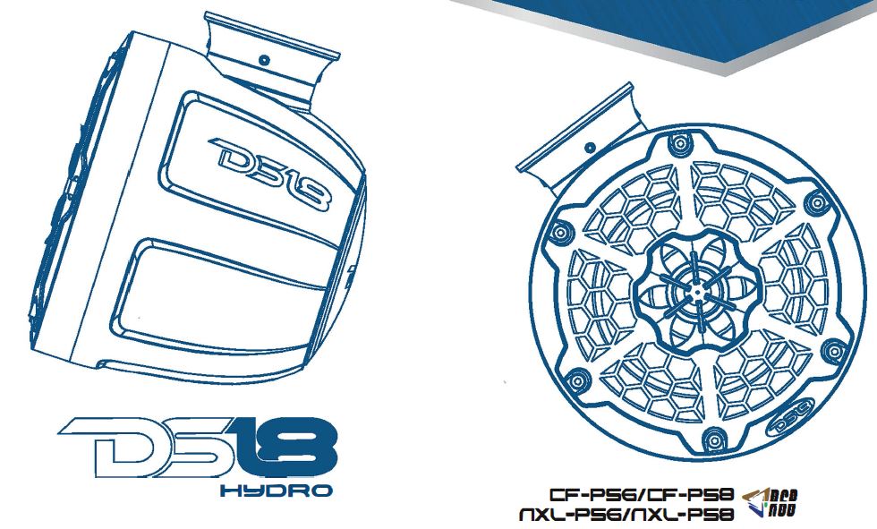
DS18 2-Way Wake board Pod Tower Speakers with Integrated RGB Lights
FEATURES
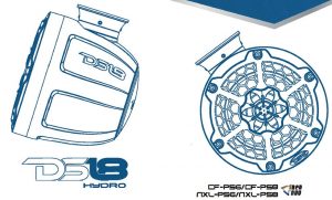
For All Elements Marine, Jeeps, Powersports & Jet SkisPair 2-Way Tower Speaker SystemCoax Separate Floating Design1″ Titanium Dome PEI Surround TweeterCNC Aluminium Base For Flat MountingDie-Cast Solid Aluminium 360-Degree Rotation Mobile Clamps For MastBuried Wire Or Open Wire Mounting Optional, Included 1.75″,2″ Clamp PartsInjection ABS/PC Enclosure (Black Matte, Red, White, Black Carbon Fiber Texture Optional) IP65 Marine-Grade CompliantInjection ABS Grill With Black Matt or High Gloss Black/White (NXL Series)Injection ABS Black Carbon Fiber Texture Grill With 316 Metal Mesh(CF Series)Integrated LED-RGB Speaker LightingInjection Molded UV-Compliant, Polypropylene ConeMotor Structure Use Y35 Ferrite Main Magnet And Reverse Neodymium Magnet6 Core Wires For Lighting And SpeakerFront Logo And Back Covers Can be Rotated For Correct Angle DisplayBT Control Module & App(LED-BTC) for Multi-Function for RGB LED Lighting (sold separately)
PACKING INCLUDESOne Pair Marine Grade Wakeboard Pods Tower System2 Sets Clamp For Mast Mounting
- 2 x Clamp Base
- 4×2″ Ring
- 4 x 1.75″ Ring
- 4 x NBR Pads For Ring
- 2 x NBR Pads For Clamp Base
2 Sets Round Flat Mounting Bracket2 x NBR Pad For Round Flat Mounting BracketHardware (Stainless): 8 x M5-45, 8 x M5 (nut), 8xM5 (Washer), 8 x M5-30 (Self-tapping),2.5mm & 4mm Hex Wrench, Vacuum Suckerowner’s Manual
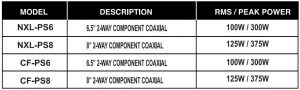
SPECIFICATIONS
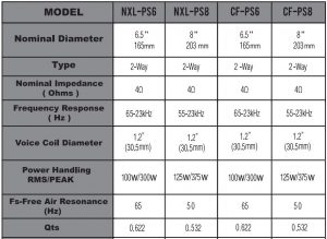
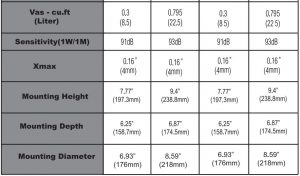
We Reserve The Right To Change Products And Specificatins At Any Time Without Notice. Images May Or May Not Include Optional Equipment
INITIAL SETUP
INSTALLATION CONSIDERATIONS:
- Be sure to carefully read and understand the instructions before attempting to install thesespeakers.
- For safety, disconnect the negative battery terminal from the battery prior to beginning theinstallation.
- For easier assembly, we suggest you have all your tools in hand- Drill, Allen set, Crimp,Soldering iron, Wire Strippers, Heat-shrink,etc.
- Use high quality “WaterProor connectors for a reliable installation and to minimize signalor power loss.
- Think before you drill! Be careful not to cut or drill into gas tank, fuel lines, brake or hydraulic lines, vacuum lines or electrical wiring when working on any vehicle. If installing in a boat, make sure not cut or drill through the main hull.
- Never run wires near fuel lines or power (if possible). Running the wires inside the hull or car area provides the best protection.
- Avoid running wires over or through sharp edges. Use rubber or plastic grommets to protect any wires routed through metal, especially the tower.
- Make sure that the mounting clamp or “L” bracket are tight before leaving the dock.
- Decide eariy what type of LED lighting you want (if any) and wire accordingly(NOTE :if you want “Dancing Lighr look to the WiFi or RF or BT remote controlled LED light box. The easy way to have lighting … YOUR way!)
PREPARING FOR INSTALLATION:
- An Electric Drill With Bits
- Allen I Hex Key I Wrench Set
- Philips Head And Standard Screw Drivers
- Wire Strippers
- Crimping Tool
- Vom (Electronic Volt Ohm Meter)
- Heat Shrink Tubing And Heat Gun
- Soldering Iron
- Electronic (Rosen Not Acid Core) solder
NOTE: The stainless steel hardware supplied with your speakers has been chosen to resist rust and corrosion. If the particular hardware supplied will not work for your installation purposes, please be sure to use only appropriate marine grade (stainless steel)mounting hardware.
INSTALLATION & CONNECTION OPTIONS
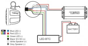
If you have an LED Control Module (LED-BTC), Connect as shown in the Following diagram:
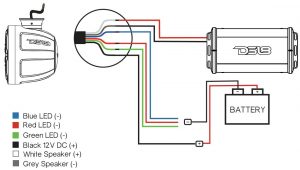
To connect without LED Control Module (LED-BTC), Connect as Shown in the Following Diagram;
Black wire “BK” Connected to battery Positive(+)12VGreen Color Light “G”Connected to Battery Negative(-)Red Color Light “R”Connected to Battery Negative(-)Blue Color Light “B”Connected to Battery Negative(-)Purple Color Light “R”and”B”Connected to Battery Negative(-)Yellow Color Light “R”and”G”Connected to Battery Negative(-)Cyan Color Light “B”and”G”Connected to Battery Negative(-)White Color Light “R”,”B” and “G” three wires Connected to Battery Negative(-)
INSTALLATION
BEGINNING MOUNTING (FLAT CLAMP INSTALL)
- Step 1: Remove pod tower speakers from the packaging and ALL hardware.
- Step 2: Packaging include two option clamps, choose Flat clamps install.
- Step 3: Find a GOOD location that allows for easy wiring of the speaker (and LED lights) – PLUS does NOT impair your movement around the location.
- Step 4: Using the supplied 2.Smm hex wrench spin out the 4-MS no head screw about 5mm, that hold the round flat rotary base.
- Step 5: Take out the NBR PAD, use it as a template to mark the location of punching and installation.
- Step 6: Use accessory screw, nut, washer to fix the round flat base with nbr pad .

- Step 7: Weld speaker wires to amplifier, RGB light wires to 12V battery or RGB controllerconnection (Attention should be paid to protect solder joints with heat shrinkable bushing or insulating adhesive tape).
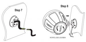
- Step 8: Put tower pod speaker mounted on flat hook base, adjust speaker angle, Using the2.5mm hex wrench spin in (Clockwise rotation) lock four MS no head screw.
- Step 9: Use the vacuum sucker to rotate the back logo to your preferred location
BEGINNING MOUNTING (MAST CLAMP INSTALL)
- Step 1 : Remove pod tower speakers from the packaging and ALL hardware.
- Step 2: Packaging include two option clamps.choose Mast clamps install.
- Step 3: Find a GOOD location that allows for easy wiring of the speaker (and LED lights) – PLUS does NOT impair your movement around the location.
- Step 4: Using the supplied 2.5mm hex wrench spin out the 4-MS no head screw about 5mm, that hold the round flat rotary base, take out the round flat base.
- Step 5: Find mast mounting base in the attachment package. Put the wire through theoutlet slot. The mast mounting base is loaded into the tower pod bracket, Lock two M5no head screw with a 2.5mm hexagonal wrench. (No locking, rotatable, wait for the mastto be mounted, adjust the angle and then lock the screw) put the rubber pad into the mastbase.
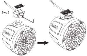
- Step 6: Find the clamp ring, rubber pad and M5-35 screw in the attachment package. Choose the appropriate clamp ring according to the size of the installation pipe. The attachment provides 2″ and 1.75″ clamp rings. First, put the rubber pad inside the clamp ring, then insert the clamp ring into the pipe. T he mast installation base of the tower pod is at the bottom of the pipe. The clamp ring is pushed into the mast installation base from the left and right sides, and inserted into the 2- MS-45. Lock it with 4mm hexagonal wrench.
- Step 7: Weld speaker wires to amplifier, RGB light wires to 12V battery or RGB controllerconneclion (Attention should be paid to protecting solder joints with heat shrinkablebushing or insulating adhesive tape}.

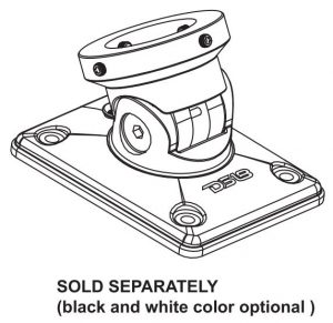
When you want the tower pod speaker to be tilted back and forth, please purchase flat clamps that can rotate back and forth. Installation method refers to the following figure.
FRONT AND BACK LOGO CAN ROTATE
![]()
FLAT MOUNTING WITH ANGLE ADJUST
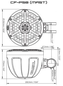
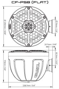
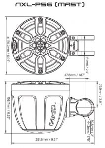
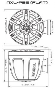
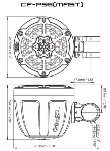
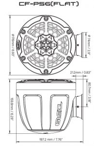
DIMENSIONS


[xyz-ips snippet=”download-snippet”]