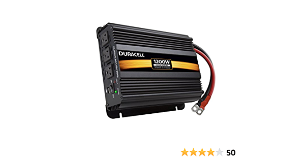
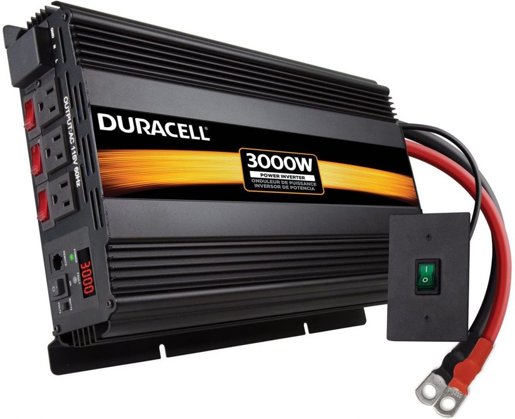
DURACELL High Power Inverter 1200W/3000W
Features
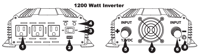
- AC outlets (3 total)
- USB port
- Inverter On/OFF switch
- Power/Faun LED lights
- Positive DC input
- Negative DC input
- Cooling vent- IMPORTANT – DO NOT COVER
- Ground connection
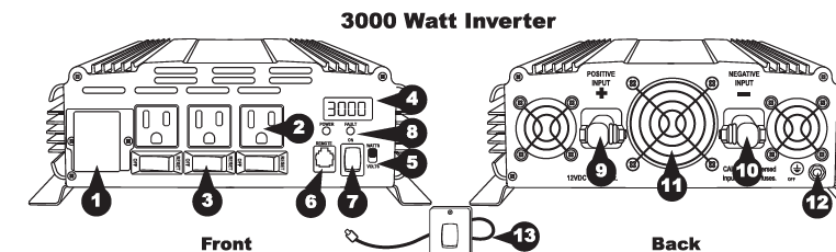
- AC output terminal
- AC outlets (3 total)
- AC ou1111t individual On/ Off+ circuit breaker
- LED digital display
- Digital display select (Watts/Volts)
- Rernol8 port
- Inverter ON\Off switch
- Power/Faun LED lights
- Positive DC input
- Negative DC input
- 3Coollngwrrts-lMPORTANT-OO NOT COVER
- Ground connection
- Rernol8 On I Off switch
Getting Started
SAVE THESE INSTRUCTIONS – this manual contains safety and operating instructions for the inverter. Misusing or incorrectly con necting the inverter may damage the equipment or create hazardous condilions for users. Read the folkM’ing safely instructions and pay special attention to all Caution and warning statements In the guide.Warning: identify conditions that may result in personal injury or loss of life.Cautions: identify conditions or practices that may damage the unit or other equipment.
IMPORTANT: Consult an electrician. Installations must meet local and national wiring codes.
Installation
Wire SelectionUse the thickest gauge and shortest length allowed by your configuration and budget. lvl a rule of thumb no more than 2% loss should be allowed. The chart below lists minimum specifications, please consult a wire gauge chart for longer installations.Failure to follow these safely guidelines may cause personal Injury and/or damage to the Inverter. It may also void ) our product warranty.
Maximum cable length (ft.) [2% wattage drop)
| Wire Gauge AWG | |||||||
| 8 | & | 4 | 2 | 1/0 | 2/0 | 4/0 | |
| I100A (1200W) | 2.9 | 4.6 | 7.2. | 11.5 | 14.5 | 23 | |
| I2sOA (3000W) | 1.8 | 2.8 | 4.6 | 5.8 | 9.2 |
IMPORTANT: All connections must be clean and tight for optimal performance. Loose connections will result In higher resistance loss of power and increased heating. Do not cover or obstruct ventilation openings.
Install in a ventilated area, leave at least 8 inches of space in front and behind the inverter for ventilation and at least 2 inches around the top and sides for the cooling fins to dissipate heat.Connecting the power cable to the inverter terminal must be in this order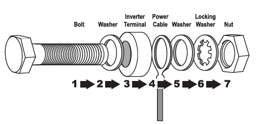
GroundingThe ground connection can be connected to earth or chassis ground depending on the Installation:
Land: Connect to earth groundVehicle: Connect to vehicle chassis of the vehicle. If power equipment is used outside the vehicle an earth-stake should be used.
WARNINGLoose connectors result in excessive voltage drop and may cause over heated wires and melted insulation, which can lead to electrical fires. Reverse polarity connections (positive to negative) will blow internal fuses in the inverter and may permanently damage the inverter.
Permanent Installation
See diagram below. Install a UL-listed fuse in-line with the red input cable, as dose ID the battery as possible. Ensure tight connections.Fuse sizeDRINV1200 :ANL-200DRINV3000: ANL-400
- Connect the negative (black) terminal of inverter lo the negative battery post.

- Connect the positive (red) 1Brminal of inverter to the positive battery post.
- Connect the ground terminal according to the GROUNDING section above.

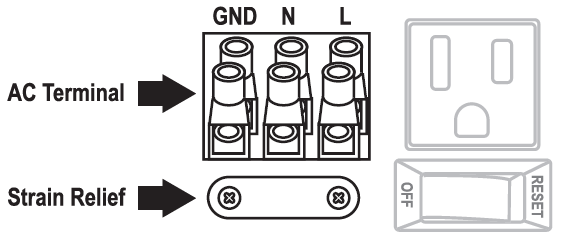
Direct Connect AC Terminal (DRINV3000 model only)
IMPORTANT: AC extension wire and socket are not included with this inverter. Each wire should be no thicker than 1 OAWG.
- Remove the cover lo access the terminals.
- Expose no more than %” of conductor from each wire and secure the rest through the strain relief.
- AC wire colors:
- Line/Hot – Black or Brown
- Neutral – White or Blue
- Ground Green or Green/Yellow
Using The Inverter
IMPORTANT: The inverter draws current in the ON position, switch it OFF to prevent it from drawing power from the batteries. See “no-load power draw” section in the specification table.
Connecting your devices/appliances:
- Ensure that all connections are secure and DC power is available.
- Connect AC devices.
- Connect USB devices (1200 Watt Inverter Only)
- Tum the Inverter On/Off switch ON.
NOTE: Tum the inverter On/Off switch to OFF when done using the inverter to avoid dischanging your battery.
IMPORTANT:Your Inverter Is able to operate several devices at once, up to Its maximum combined load. The 1200 Watt Inverter can power a combined load of up to 1200 Watts of continuous power. The 3000 watt can power a combined load of up lo 3000 Watts of continuous power. If the total power draw of the connected devices, tools and/or appliances exceeds this maximum, the inverter will automatically shut down to avoid dangerous overload. The chart below shows an approximation of typical wattages for popular electrical items. Please consult the manual(s) of your device(s) to determine the exact wattage of your particular model.
LED display (3000 Watt Inverter only)Use the digital display select switch to show AC output power in Wal1ll or battery voltage in \lolls.Remote On/Off switch (3000 Watt Inverter only)In order to use the remote, the inverter On/Off switch must be in the OFF position. Toe inverter can then be turned ON or OFF with the remote switch.
Safety
Under Voltage:At 10.5 +- 0.3V input an alarm sound, at 10.0V the inverter shuts down and the FAULT LED turns on. This protects the battery from over discharge.
Over Voltage:If the input Voltage is >15V, an alarm sound, the inverter shuts down to protect itself and the FAULT LED will illuminate.
Over Load:When power output exceeds the rated continuous power for extended periods of time or the surge power for more than 20 seconds the inverter will shut down. After the excessive load is removed the inverter can be restored by turning it on and off.
Over Temperature:An alarm will sound and the FAULT LED will illuminate if the inverter overheats and will shut down if it does not cool down. Poor ventilation over load or high room temperature can cause an overheating condition. The cooling fan is temperature controlled and turns on to prevent overheating during normal operation.
Short Circuit:When an output short circuit occurs, the inverter will beep, the FAULT LED will turn on and the inverter will shut down.
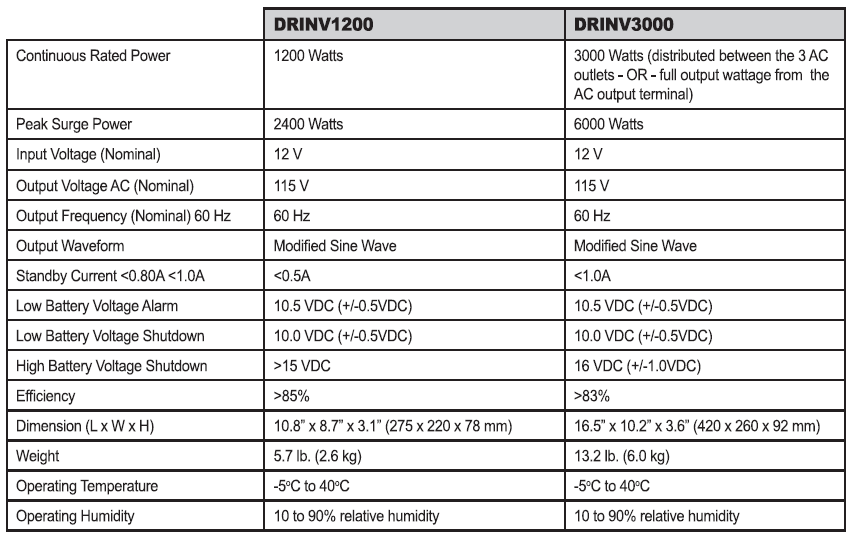
Specification:
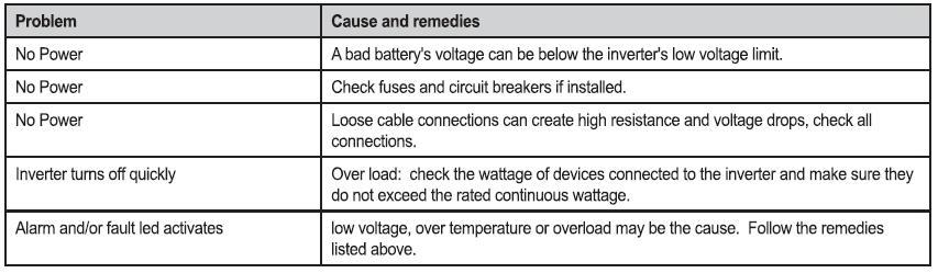
Troubleshooting:
[xyz-ips snippet=”download-snippet”]