![]()
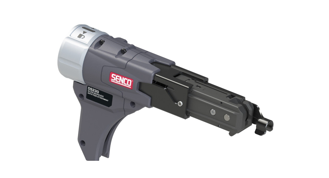
![]() DS230AUTO-FEED SCREW SYSTEM ATTACHMENTOperating Instructions
DS230AUTO-FEED SCREW SYSTEM ATTACHMENTOperating Instructions
 IMPORTANT: Read before use.
![]() KYOCERA SENCO Industrial Tools4270 Ivy Pointe Blvd.Cincinnati, OH 452451-800-543-4596www.senco.comNFD89Z • Issued April 1, 2020© 2020 by KYOCERA-SENCO Industrial Tools, Inc.
KYOCERA SENCO Industrial Tools4270 Ivy Pointe Blvd.Cincinnati, OH 452451-800-543-4596www.senco.comNFD89Z • Issued April 1, 2020© 2020 by KYOCERA-SENCO Industrial Tools, Inc.
SYMBOLS
| The following signal words and meanings are intended to explain the levels of risk associated with this product. | ||
|
SYMBOL |
SIGNAL |
MEANING |
 |
DANGER: | Indicates a hazardous situation, which, if not avoided, will result in death or serious injury. |
|
WARNING: | Indicates a hazardous situation, which, if not avoided, could result in death or serious injury. |
|
CAUTION: | Indicates a hazardous situation, which, if not avoided, may result in minor or moderate injury. |
| NOTICE: | (Without Safety Alert Symbol) indicates information considered important, but not related to a potential injury (e.g. messages relating to property damage). |
Some of the following symbols may be used on this product. Please study them and learn their meaning.Proper interpretation of these symbols will allow you to operate the product in a better, safer manner.
| SYMBOL | NAME |
DESIGNATION/EXPLANATION |
|
Alert | Indicates a potential personal injury hazard. |
 |
Read Operator’s Manual | To reduce the risk of injury, users must read and understand the operator’s manual before using this product. |
 |
Eye Protection | Always wear eye protection with side shields marked to comply with ANSI Z87.1. |
 |
Wet Conditions Alert | Do not expose to rain or use in damp locations. |
 |
No Hands | Failure to keep your hands away from the blade will result in serious personal injury. |
 |
Recycle | This product uses Lithium-ion batteries. Local, state or federal laws may prohibit the disposal of batteries in ordinary trash. Consult your local waste authority for information regarding available recycling and or disposal options. |
|
V |
Volts | Voltage |
|
min |
Minutes | Time |
| Direct Current | Type or characteristic of current | |
|
no |
No Load Speed | Rotational speed, at no load |
|
…/min |
Per Minute | Revolutions, strokes, surface speed, orbits, etc. per minute |
General Power Tool Safety Warnings
![]() WARNINGRead all safety warnings, instructions, illustrations, and specifications provided with this power tool.Failure to follow all instructions listed below may result in electric shock, fire, and/or serious injury.Save all warnings and instructions for future reference.The term “power tool” in the warnings refers to your mains-operated (corded) power tool or battery-operated (cordless) power tool.WORK AREA SAFETY
WARNINGRead all safety warnings, instructions, illustrations, and specifications provided with this power tool.Failure to follow all instructions listed below may result in electric shock, fire, and/or serious injury.Save all warnings and instructions for future reference.The term “power tool” in the warnings refers to your mains-operated (corded) power tool or battery-operated (cordless) power tool.WORK AREA SAFETY
- Keep your work area clean and well-lit.Cluttered or dark areas promote accidents.
- Do not operate power tools in explosive atmospheres, such as in the presence of flammable liquids, gases, or dust.Power tools create sparks that may ignite dust or fumes.
- Keep children and bystanders away while operating a power tool.Distractions can cause you to lose control.
- The included auto-feed screwdriver attachment was designed to work with one make and several models of power screwdrivers.Refer to the screwdriver manufacturer’s operator’s manual for related safety and operating instructions.ELECTRICAL SAFETY
- Power tool plugs must match the outlet.Never modify the plug in any way. Do not use any adapter plugs with earthed (grounded) power tools. Unmodified plugs and matching outlets will reduce the risk of electric shock.
- Avoid body contact with earthed or grounded surfaces, such as pipes, radiators, ranges, and refrigerators.There is an increased risk of electric shock if your body is earthed or grounded.
- Do not expose power tools to rain or wet conditions.Water entering a power tool will increase the risk of electric shock.
- Do not abuse the cord.Never use the cord for carrying, pulling, or unplugging the power tool. Keep cord away from heat, oil, sharp edges, or moving parts. Damaged or entangled cords increase the risk of electric shock.
- When operating a power tool outdoors, use an extension cord suitable for outdoor use.The use of a cord suitable for outdoor use reduces the risk of electric shock.
- Hold power tool using its insulated gripping surfaces when performing an operation where the fastener may come into contact with hidden wiring.Fasteners that come into contact with a “live” wire may make exposed metal parts of the power tool “live” and could give the operator an electric shock.PERSONAL SAFETY
- Stay alert, watch what you are doing, and use common sense when operating a power tool.Do not use a power tool while you are tired or under the influence of drugs, alcohol, or medication. A moment of inattention while operating power tools may result in serious personal injury.
- Use personal protective equipment. Always wear eye protection.Protective equipment such as dust masks, non-skid safety shoes, hard hats, or hearing protection used for appropriate conditions will reduce personal injuries.
- Prevent unintentional start-up.Ensure the switch is in the off position before connecting to a power source and/or battery pack, picking up or carrying the tool. Carrying power tools with your finger on the switch or energizing power tools that have the switch on promotes accidents.
- Remove any adjusting key or wrench before turning the power tool on.A wrench or a key left attached to a rotating part of the power tool may result in personal injury.
- Do not overreach. Keep proper footing and balance at all times.This enables better control of the power tool in unexpected situations.
- Dress properly.Do not wear loose clothing or jewelry. Keep your hair, clothing, and gloves away from moving parts. Loose clothes, jewelry or long hair can be caught in moving parts.
- IIf devices are provided for dust extraction and collection, ensure these are connected and properly used.The use of dust collection can reduce dust-related hazards.
- Do not let familiarity gained from frequent use of tools allow you to become complacent and ignore tool safety principles.A careless action can cause severe injury within a fraction of a second.POWER TOOL USE AND CARE
- Do not force the power tool. Use the correct power tool for your application.The correct power tool will provide better, safer results when used according to its specifications.
- Do not use the power tool if the power switch is defective.Any power tool that cannot be controlled with the switch is dangerous and must be repaired.
- Disconnect the plug from the power source and/or remove the BATTERY pack, if detachable, from the power tool before making any adjustments, changing accessories, or storing power tools.Such preventive safety measures reduce the risk of starting the power tool accidentally.
- Store idle power tools out of the reach of children and do not allow persons unfamiliar with the power tool or these instructions to operate the power tool.Power tools are dangerous in the hands of untrained users.
- Maintain power tools and accessories.Check for misalignment or binding of moving parts, breakage of parts, and any other condition that may affect the power tool’s operation. If damaged, have the power tool repaired before use. Many accidents are caused by poorly maintained power tools.
- Keep cutting tools sharp and clean.Properly maintained cutting tools with sharp cutting edges are less likely to bind and are easier to control.
- Use the power tool, accessories and tool bits, etc. in accordance with these instructions, taking into account the working conditions and the work to be performed.Use of the power tool for operations that differ from its intended purpose could result in a hazardous situation.
- Keep handles and grasping surfaces dry, clean, and free from oil and grease.Slippery handles and grasping surfaces do not allow for safe handling and control of the tool in unexpected situations.SERVICE
- Have your power tool serviced by a qualified repair person using only identical replacement parts.This will ensure that the safety of the power tool is maintained.
- Users or full-service dealers need to be aware that spring is housed inside the feed system. It will release from its constrained position during disassembly.Normal precautions should apply.
Functional Description

 |
 |
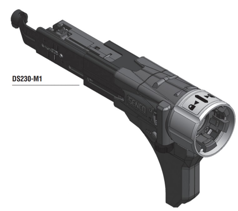
For a complete list of compatible tool models, please visit Senco.com.
 |
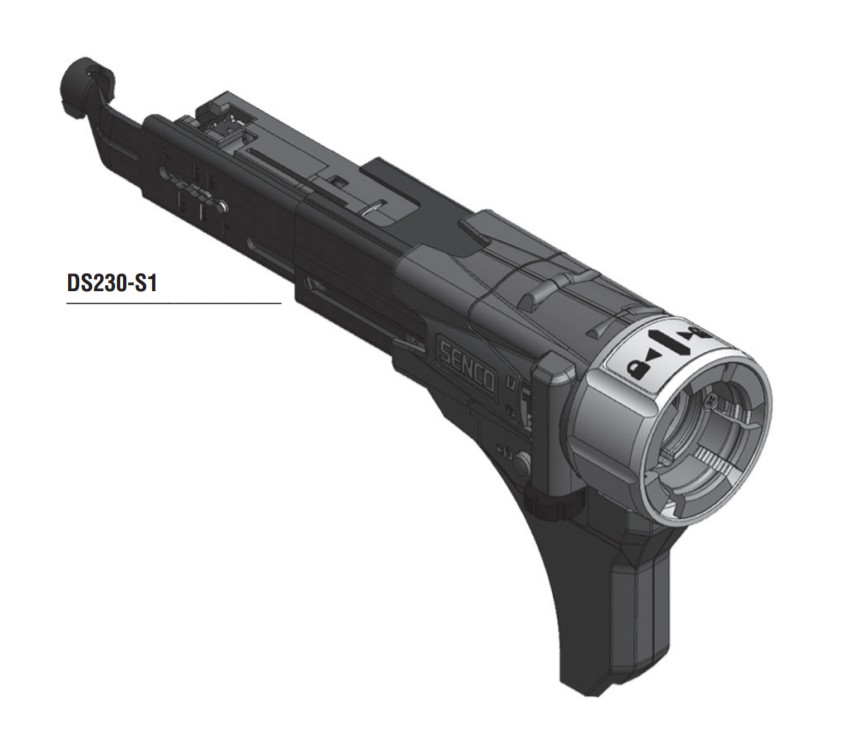 |
For a complete list of compatible tool models, please visit Senco.com.
Tool Operation
Read sections titled “Safety Warnings” before operating the tool.![]() WARNING Do not use this product if it is not completely assembled or if any parts appear to be missing or damaged. Use of a product that is not properly and completely assembled or with damaged or missing parts could result in serious personal injury.
WARNING Do not use this product if it is not completely assembled or if any parts appear to be missing or damaged. Use of a product that is not properly and completely assembled or with damaged or missing parts could result in serious personal injury.![]() WARNING Do not attempt to modify this product or create accessories or attachments not recommended for use with this product. Any such alteration or modification is misuse and could result in hazardous conditions possibly leading to serious personal injury.
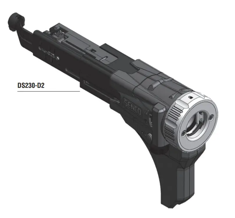
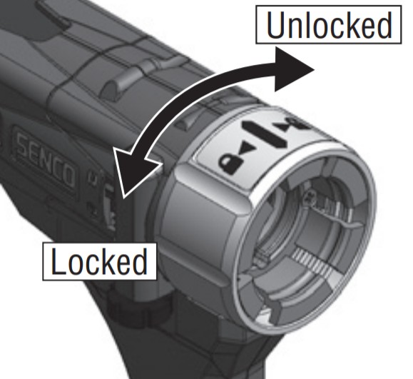
WARNING Do not attempt to modify this product or create accessories or attachments not recommended for use with this product. Any such alteration or modification is misuse and could result in hazardous conditions possibly leading to serious personal injury.![]() CAUTION Do not rotate the attachment collar in the locking direction if not fully installed onto a tool. This could damage the connector components.If any parts are damaged or missing, please call 1-800-543-4596 for assistance.INSTALLING A DS230-M1, DS230-S1, DS230-D2 ATTACHMENT
CAUTION Do not rotate the attachment collar in the locking direction if not fully installed onto a tool. This could damage the connector components.If any parts are damaged or missing, please call 1-800-543-4596 for assistance.INSTALLING A DS230-M1, DS230-S1, DS230-D2 ATTACHMENT
- Unplug the tool from the electrical supply or remove the battery before installing the attachment.
- Remove the manufacturer’s nose cone from the tool.
- Remove manufacturer’s bit and holder if present.
- Install the appropriate Senco bit (see below), making sure it is fully seated (this may require some force.)
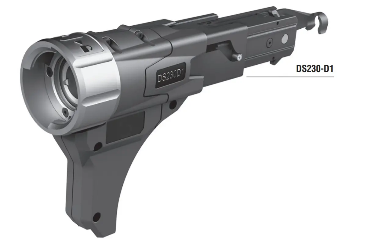
- Make sure the attachment locking collar is in the unlock position and slide completely onto the tool.(Note: DS230 models are designed to fit specific screwdrivers. Therefore, they look slightly different with unique connection features depending on the brand of a screwdriver. Refer to the images on the previous page.
- Rotate the collar counterclockwise to engage and lock the attachment to the tool.
| Bit Type | DS230 |
| Phillips | EA0300 |
| Square | EA0301 |
| Rex | EA0302 |
INSTALLING THE DS230-D1 ADAPTER AND ATTACHMENT
- To prepare the screw gun before installing the screw-on adapter.
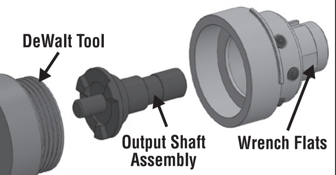
 a. Unplug the tool from the electrical supply or remove the battery before installing the attachment.b. Remove the nose cone – This can be reinstalled onto the Senco-provided adapter installed in step e. Please note that the internal tabs in the nose cone must be aligned with the adapter slots, and the depth may need to be adjusted to install properly.c. Remove manufacturer’s bit and holder if present.d. Unscrew the stock DeWalt clutch housing by rotating clockwise (threads are left-hand/reversed). The use of a wrench may be necessary.e. Remove the output shaft assembly from the stock clutch housing and reinstall it into the supplied Senco adapter and thread onto the DeWalt tool by rotating counterclockwise.f. Torque adapter onto the tool to 50 in. lbs. with an adjustable wrench.
 - Install the bit and the attachment onto the tool as described in steps 4-6 in the previous section.
 a. Unplug the tool from the electrical supply or remove the battery before installing the attachment.b. Remove the nose cone – This can be reinstalled onto the Senco-provided adapter installed in step e. Please note that the internal tabs in the nose cone must be aligned with the adapter slots, and the depth may need to be adjusted to install properly.c. Remove manufacturer’s bit and holder if present.d. Unscrew the stock DeWalt clutch housing by rotating clockwise (threads are left-hand/reversed). The use of a wrench may be necessary.e. Remove the output shaft assembly from the stock clutch housing and reinstall it into the supplied Senco adapter and thread onto the DeWalt tool by rotating counterclockwise.f. Torque adapter onto the tool to 50 in. lbs. with an adjustable wrench.
TOOL OPERATION
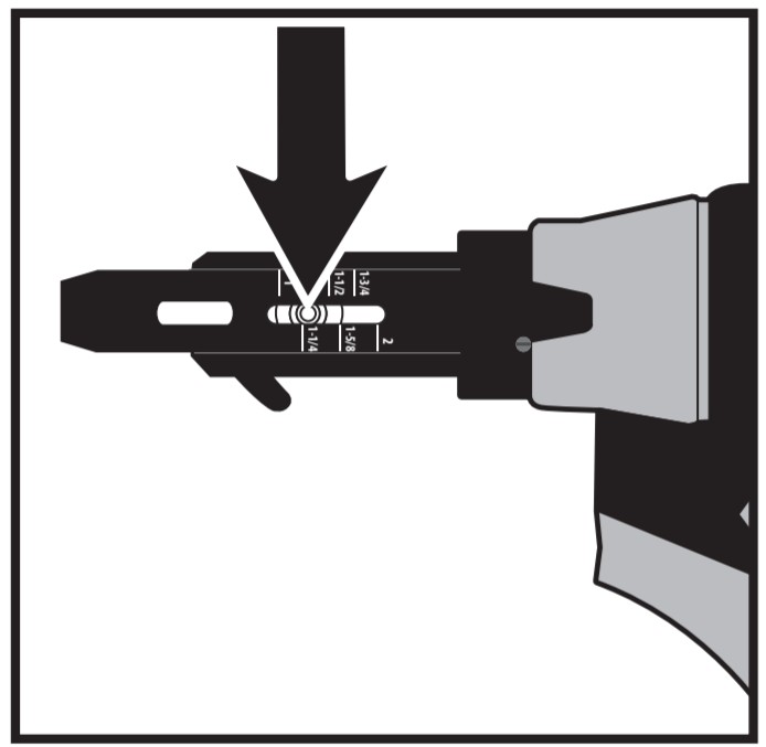
ADJUSTING FOR FASTENER LENGTH
- Remove battery before adjusting nosepiece for fastener length.
- Depress the screw selector pin until it is flush with the nosepiece and slide the nosepiece to the desired setting by aligning hatch marks with the silver adjustment pin.
- Release pin ensuring it is fully engaged in selected nosepiece slot for proper operation.
LOADING THE TOOL![]() CAUTION Beware of sharp points on screws. Avoid grabbing this area during loading andoperation.
CAUTION Beware of sharp points on screws. Avoid grabbing this area during loading andoperation.
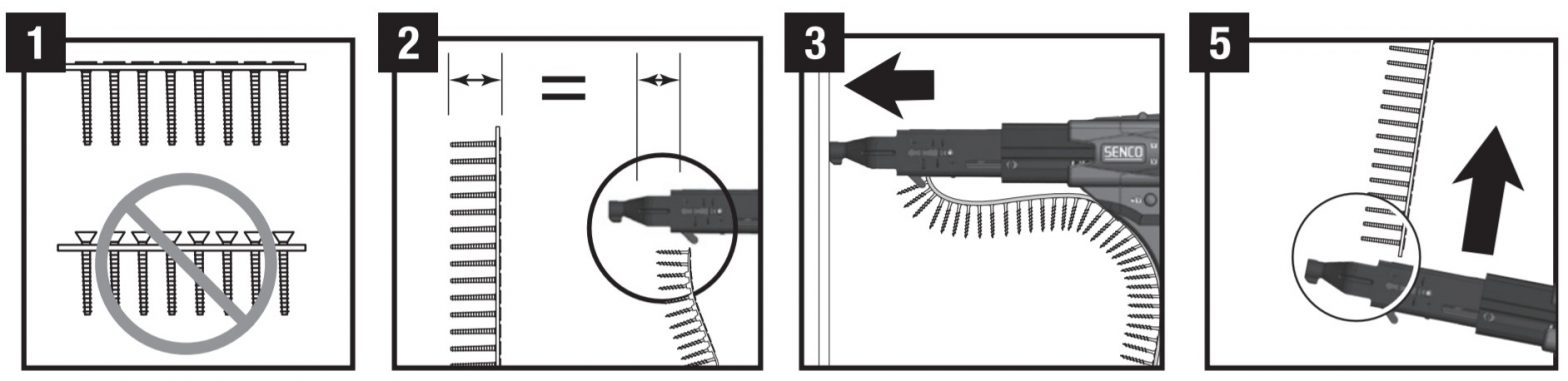
- Make sure the heads of the screws are resting on top of the plastic collation material.This will ensure proper strip advancement and prevent jamming.
- Check for proper fastener length setting (see “Adjusting for Fastener Length” above).
- Feed the strip into the strip guide up toward the nose of the tool.
- Feed the strip into the slide body until the first screw is aligned with the bit. The tool will feed all subsequent screws automatically as the tool is pulled back off the work surface, returning to its relaxed state.
- To remove the strap, pull it through from the top of the nosepiece.
VING SCREWS
- Whenever possible, hold the tool at a right angle (perpendicular) to the work surface.
- Pull the trigger to start the motor.
- Press the nosepiece with constant force against the work surface.Do not remove the tool from the work surface until the clutch disengages and the bit stops rotating, signaling a fully driven screw.
- Continue to allow the motor to run. The next screw will be automatically fed into place when the tool is pulled off the work surface.
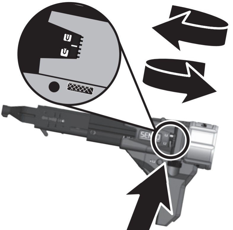
DEPTH OF DRIVE ADJUSTMENTThis tool is equipped with a locking depth control adjustment:
- Release the thumbwheel by depressing the red lock button.
- Adjust the countersink by turning the depth adjustment thumbwheel.
- Refer to the markings on the tool for proper direction.
- Release the lock button after adjustment.
Test drive screws while adjusting until the desired countersink is reached.
 REVERSE OPERATIONTo operate the tool in reverse for removal of screws (refer to Figure 1):
- Flip the forward/reverse switch on the tool to reverse rotation.
- Turn the locking collar on the attachment to the unlock position.
- Slide the attachment of the tool to expose the bit.
- Insert the bit into the screw and apply/maintain pressure to engage the clutch.
- Pull trigger until the screw is completely disengaged.
BIT REPLACEMENTDue to wear or damage, the bit will need to be replaced periodically or when changing between drive types.![]() CAUTIONRemove the battery or unplug the tool before attempting to replace the bit.
CAUTIONRemove the battery or unplug the tool before attempting to replace the bit.
- Turn the locking collar on the attachment to the unlock position.
- Slide the attachment of the tool to expose the bit.
- Remove bit per tool manufacturer’s instructions
- Insert the new bit per the tool manufacturer’s instructions.
- Install attachment and rotate collar to lock position.
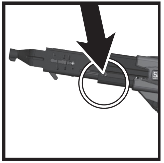
NOSEPIECE REPLACEMENT
- Remove the battery or unplug the tool before changing the nosepiece.
- Remove retention screw with a flat-tip screwdriver.
- Set the nosepiece on the longest setting possible.
- Depress the screw selector pin until it is completely depressed. It will be necessary to use a screw or thin object to depress to this depth
- While holding the pin in this position, slide the nosepiece forward and off the slide body.
- Install the new nosepiece.
- Replace the nosepiece retention screw ensuring it is seated snug against the slide body.
- Check for proper fastener length setting (see “Adjusting for Fastener Length” above).
Maintenance
Read the section titled “Safety Warnings” before maintaining the tool.
- With the battery removed or cord disconnected, make a daily inspection to ensure free movement of the nosepiece and trigger. Do not use the tool if the nosepiece or trigger sticks or binds.
- Lubrication of the feed system is not necessary. DO NOT OIL.
- Wipe tool clean daily and inspect for wear, especially the bit and nosepiece. Replace as necessary.
![]() WARNINGRepairs other than those described here should be performed only by trained, qualified personnel. Contact SENCO for information at 1-800-543-4596.
WARNINGRepairs other than those described here should be performed only by trained, qualified personnel. Contact SENCO for information at 1-800-543-4596.
Accessories
SENCO offers a full line of DuraSpin screws and accessories for your SENCO tools, including
- Bits
- Storage Bag
- Assorted Nosepieces
- Safety Glasses
For more information or a fully illustrated catalog of Senco accessories, contact your sales representative or call Senco at 1-800-543-4596
Technical Specifications
Table 3 – DS230 Tech Specs
| SPECIFICATION | DS230-M1/S1 | DS230-D1 | DS230-D2 |
| WEIGHT | 1.3 LBS. (0.579 KG) | 1.3 LBS. (0.578 KG) | 1.3 LBS. (0.580 KG) |
| HEIGHT | 5.53″ (140.5 MM) MAX | 5.53″ (140.5 MM) MAX | 5.53″ (140.5 MM) MAX |
| LENGTH | 11″ (279.5 MM) MAX | 10.79″ (273.98 MM) MAX | 10.34″ (262.71 MM) MAX |
| WIDTH | 2.47″ (372.4 MM) MAX | 2.47″ (372.4 MM) MAX | 2.47″ (372.4 MM) MAX |
| FASTENER CAPACITY | 50 SCREWS (1 STRIP) | 50 SCREWS (1 STRIP) | 50 SCREWS (1 STRIP) |
| FASTENER LENGTH | 1-2″ | 1-2″ | 1-2″ |
| FASTER RANGE | #6-#12 | #6-#12 | #6-#12 |
Troubleshooting
|
Problem/Symptom |
Probable Cause |
Corrective Action |
| The tool will not fully drive the fastener
|
Bit is worn | Replace bit |
| Power capabilities of the tool have been exceeded | Discontinue use in that application | |
| Todi is in reverse | Switch tool to forward | |
| Incorrect bit installed | Ensure correct bit type and length are installed | |
| Depth of drive not set properly | See p. 10 for proper adjustment | |
| The tool does not advance the fastener
|
Screw length is improperly set | See p. 9-10 for proper adjustment |
| Return spring is weak | Replace or return to an authorized service center for repair | |
| Defective collation material | Use Senco branded fasteners for optimum performance | |
| Defective slide body | Replace or return to Senco authorized service center for repair | |
| The screw strip is jammed in the guide track | Ensure strip slides free in the guide track | |
| Screws “kick out” or misdrive during use
|
Screw length improperly set | See p. 9-10 for proper adjustment |
| Incorrect bit installed | Ensure correct bit type and length are installed | |
| Defective or damaged feed system | Return to Senco Authorized service center for repair | |
| Bit slips off screw or screw are driven at an angle
|
Tool slid forward during the drive | Hold tool firmly while driving |
| The bit is worn or broken | Replace bit | |
| Nosepiece is worn or damaged | Replace or return to Senco authorized service center for repair | |
| Fastener jams
|
Screw length improperly set | See p. 9-10 for proper adjustment |
| Defective collation material | Use Senco branded fasteners for optimum performance | |
| Nosepiece damaged or bent | Replace nosepiece | |
| Screw partially driven into collation material then feed system released | Remove the jammed screw with fingers or pliers and resume use | |
| Slide mechanism “sticks” or returns slowly
|
Debris build-up in mechanism | Clean mechanism |
| Weak return spring | Replace or return to Senco authorized service center for repair | |
| Bit sticking in collation material | Use Senco branded fasteners for optimum performanceAlways attempt to store screws in a cool, dry place before use. Overheated collation can get soft and cause a delay in feed system return | |
| Pushing force becomes excessive | Improper screw for application | Consider alternative fastener |
| CAM screw is loose or damaged | Tighten or replace CAM screw | |
| Debris build-up on the mechanism | Clean mechanism | |
| The attachment will not fully installAock | The attachment is not fully inserted- ed and seated onto the tool | Verify that the attachment is fully seated before attempting to lock the collar |
| The collar is not turned to the full unlock position | Partially install the tool as far on as possible and rotate the collar to a full unlock position | |
| A foreign object stuck inside the attachment | Make sure that no objects or parts are jammed inside the connection | |
| Components in the connector may be damaged | Replace connector or return to Senco Authorized service center for repair | |
| The attachment will not fully uninstalVunlock | The collar is not turned to the full unlock position | Rotate the collar to full unlock position |
| The attachment is catching on the front end of the tool | Avoid removing at any angle, pull attachment straight off and away from the tool to remove | |
| When in full unlock position, maneuver attachment up and down to disengage grabbing features from the tool | ||
| A foreign object stuck inside the attachment | Be sure that no objects or parts are jammed inside the connection | |
| Components in the connector may be damaged | Replace connector or return to Senco Authorized service center for repair | |
| The attachment will not rotate index independently of the connector | Damage or failure of indexing components | Replace connector or return to Senco Authorized service center for repair |
Limited Warranty SENCO®Pneumatic, DuraSpin®,Cordless Tools & Compressors
KYOCERA-SENCO Industrial Tools, Inc. (“SENCO”) designs and constructs its products using the highest standards of material and workmanship. SENCO warrants to the original retail purchaser that the following products will be free from defects in material or workmanship for the warranty period
| Products | New | Reconditioned |
| Pneumatic Tools * | Five Years | One Year |
| Fusion Tools | Two Years | Six Months |
| Gas Tools | Two Years | Six Months |
| Duraspin Tools | Five Years | 90 Days |
*= Both XP and Pro Series
| Products | Products | Reconditioned |
| Air Compressors | Air Compressors | 90 Days |
| Combo Kit Tools | Combo Kit Tools | 90 Days |
| Multi-Blow Hand Nailers | Multi-Blow Hand Nailers | 90 Days |
| Stapling Hammers | Stapling Hammers | 90 Days |
During the warranty period (which begins on the purchase date), SENCO will repair or replace, at SENCO’s option and expense, any product or part that is defective in materials or workmanship after examination by a SENCO Authorized Warranty Service Centre, subject to the exceptions, exclusions, and limitations described below. Any replacement product or part will carry an arranty for the balance of the warranty period applicable to the replaced product or part. A DATED SALES RECEIPT OR PROOF OF PURCHASE FROM THE ORIGINAL RETAIL PURCHASER IS REQUIRED TO MAKE A WARRANTY CLAIM. Warranty registration is also required and can be accomplished through online Product Registration at www.senco.com or by completing and returning the postage paid warranty registration form included with your Operator’s manual/parts chart information, found inside the product carton. To make a warranty claim, you must return the product, with proper receipt/proof of purchase and return transportation charges prepaid, to a SENCO Authorized Warranty Service Centre. A list of SENCO Authorized Warranty Service Centres can be found at www.senco.com or by calling 1-800-543-4596 toll-free.SENCO will perform its obligations under this warranty within a reasonable time after approval of the warranty claim.SENCO Cordless:
- Subject to the exceptions, exclusions, and limitations described below, SENCO warrants that the SENCO Cordless tool will be free from defects in materials and workmanship for two years after the purchase date.
- SENCO warrants that the batteries and chargers used with SENCO Cordless tools will be free from defects in material and workmanship for one year after the purchase date.
Warranty ExclusionsThe following warranty exclusions apply:
- seals, driver blades, piston stops, and piston/driver assembly.
- This warranty does not cover parts damaged due to normal wear, misapplication, misuse, accidents, operation beyond the recommended speeds or voltage (electric units only), improper storage, or damage resulting from shipping.
- Products used in production/industrial applications as defined by SENCO are excluded from this warranty.
- Labor charges or loss or damage resulting from improper operation, maintenance, or repairs are not covered by this warranty.
General Warranty ConditionsThis warranty will be honored only if:A. Clean, dry, regulated compressed air has been used, at air pressure not exceeding the maximum indicated on the tool casting;B. No evidence of abuse, abnormal conditions, accident, neglect, misuse, or improper modifications or storage of the product; and C. No deviation from operating instructions, specifications, and maintenance schedules exists (read Operator Manual for use, specifications, and maintenance instructions).THIS WARRANTY IS THE ONLY WARRANTY ON THE PRODUCT, AND SENCO DISCLAIMS ALL OTHER WARRANTIES. ANY IMPLIED WARRANTIES WILL BE LIMITED IN DURATION TO THE APPLICABLE WARRANTY PERIOD SPECIFIED ABOVE. SOME STATES DO NOT ALLOW LIMITATIONS ON HOW LONG AN IMPLIED WARRANTY LASTS, SO THE ABOVE LIMITATION MAY NOT APPLY TO YOU. YOUR REMEDIES ARE SOLELY AND EXCLUSIVELY AS STATED ABOVE. SENCO SHALL IN NO EVENT BE LIABLE FOR INCIDENTAL, CONSEQUENTIAL, INDIRECT, OR SPECIAL DAMAGES. SOME STATES DO NOT ALLOW THE EXCLUSION OR LIMITATION OF INCIDENTAL OR CONSEQUENTIAL DAMAGES, SO THE ABOVE LIMITATION OR EXCLUSION MAY NOT APPLY TO YOU. IN NO EVENT, WHETHER AS A RESULT OF A BREACH OF CONTRACT, WARRANTY, TORT (INCLUDING NEGLIGENCE), OR OTHERWISE, SHALL SENCO’S LIABILITY EXCEED THE PRICE OF THE PRODUCT WHICH HAS GIVEN RISE TO THE CLAIM OR LIABILITY. ANY LIABILITY CONNECTED WITH THE USE OF THIS PRODUCT SHALL TERMINATE UPON THE EXPIRATION OF THE WARRANTY PERIOD SPECIFIED ABOVE. NO EMPLOYEE OR REPRESENTATIVE OF SENCO OR ANY DISTRIBUTOR OR DEALER IS AUTHORIZED TO MAKE ANY CHANGE OR MODIFICATION TO THIS WARRANTY.This warranty gives you specific legal rights, and you may also have other rights which vary from state to state.Replacement of Tool Due to Natural DisasterSENCO will replace any tool destroyed by an Act of God such as flood, earthquake, hurricane, or other disaster resulting only from the forces of nature. Such a claim will be honored provided that the original retail purchaser had previously submitted a completed warranty registration card for the tool. and then submits proof of ownership and an acceptable statement describing such Act of God documented by an insurance carrier, police department. or another official governmental source. To obtain instructions for filing a claim call 1-800-543-4596.Customer SatisfactionIf for any reason the product does not perform to the original purchaser’s satisfaction, it can be returned to the place of purchase within thirty days with a dated sales receipt for a full refund of the purchase price (applies to new product sales only).©2019 KYOCERA-SENCO Industrial Tools, Inc.CINCINNATI. OHIO 45244-1611 THE USAwww.senco.com160101
![]() KYOCERA SENCO Industrial Tools4270 Ivy Pointe Blvd.Cincinnati, OH 452451-800-543-4596www.senco.com© 2019 by KYOCERA-SENCO Industrial Tools, Inc.
KYOCERA SENCO Industrial Tools4270 Ivy Pointe Blvd.Cincinnati, OH 452451-800-543-4596www.senco.com© 2019 by KYOCERA-SENCO Industrial Tools, Inc.
References
[xyz-ips snippet=”download-snippet”]