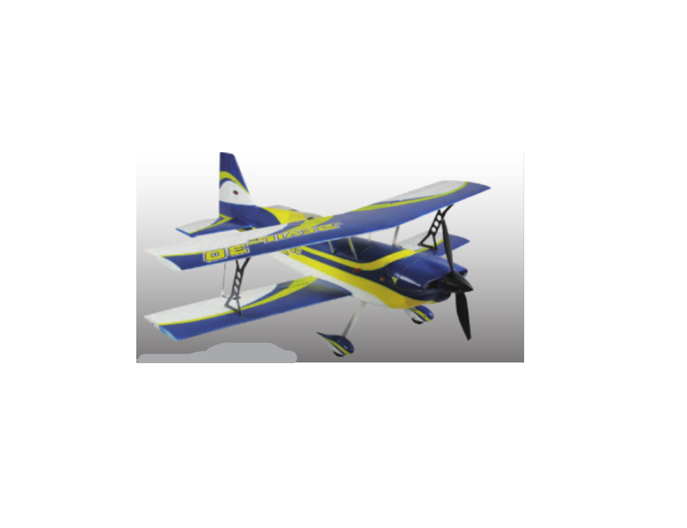
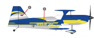
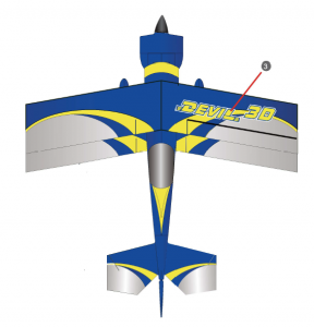
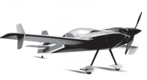
Dynam Devil 3D DY8954 Instruction Manual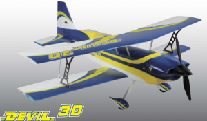
Specification:
Wingspan: – – – – – – -1016mm (40in)Overall Length: – – – – -1130mm (44.5in)Wing Loading: – – – – – 55g/dm2Servo: – – – – – – – – 9gx2pcs, 17gx2pcsBattery: – – – – – – – – 14.8V 2200mAh Li-Po, 25CSpeed Controller: – – – – 50A BrushlessMotor Size: – – – – – – – BM3720A-KV650 Brushless OutrunnerFlying Weight: – – – – – 1450g(51.2oz)
 SAFETY PRECAUTIONS This radio control model is not a toy!
 SAFETY PRECAUTIONS This radio control model is not a toy!
- First-time builders should seek advice from people having building experience in order to assemble the model correctly and to produce its performance to full extent.
- Assemble this kit only in places out of children’s reach!
- Take enough safety precautions prior to operating this model. You are responsible for this model’s assembly and safe operation!
- Always keep this instruction manual ready at hand for quick reference, even after completing the assembly.
Safety Precautions
♦ Never fly the Airplane where there are crowds of people, power linese overhead, automobiles or near highways.give yourself plenty of room for flying,as the plane can travel at a high rate of speed.Remember you are responsible for the safety of others.♦ Do not fly in strong winds.♦ Do not attempt to catch the Airplane while flying.♦ Children under the age of 16 should not have admission to the transmitter for the plane.♦ Never leave this system unattended.with the batteries in the unit and around children. Injury can result by children turning on the transmitter or the plane.♦ Keep away from the propeller at all times.The system can automatically start when the batteries are plugged in, regardless if the transmitter is in the on or off position.The propeller can cause injury!♦ Before flying, always remember to turn on the transmitter first, before plugging in the battery pack.Stay clear of propeller.♦Always turn the speed controller all the way down and the switch on “OFF”.(left control stick in the down position) before starting; otherwise the propeller will strat on full power when you plug the battery into the plane.♦After running the motor,disconnect the battery first before turning off the transmitter, otherwise the propeller may staat at full power.♦ Never leave the charger or battery near wet areas.♦ Completely discharging a Li-poly battery can result in permanent damage to the cells of the battery.Therefore you must always remember to disconnect the battery after using the plane.
Before You Begin
♦ Read through the manual before you begin,so you will have an overall idea of what to do.♦ Check all parts. If you find any defective or missing parts contact your local dealer.Please DRY FIT and check for defects for all parts that will require CA or Epoxy for final assembly.Any parts you find to be defective after the gluing process may be difficult to remove for warranty replacement .The manufacturer will replace any defective parts,but will be difficult to extend to the good parts that are good before bluing to defective parts during assembly .♦ Symbols used throughout this instruction manual comprise of following:
 Apply epoxy glue
 Assemble left and right iL…!J sides the same way.
 Pay close attention here!
 pliers
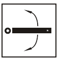 Ensure smooth non-binding [ZJ movement while assembling.
 Cut off shaded portion
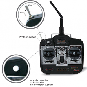
How to use your dynam 2.4G re system
important
- Put down throttle sticker.
- Turn on transmitter power-switch.
- Please let your receiver connect with battery in 10 seconds.
- Check your protect-switch, when protect-switch in up station,put down,release from protect. when protect-switch in down station,put up frist,then put down again, release from protect,you can fly now .
RTF Including
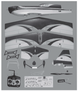
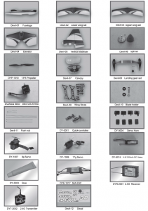
RTF including:
Fuselage■ Lower wing set ■ Propeller■ Upper wing set ■ Spinner■ Elevator ■ Decal■ Landing gear ■ Li-Po battery (14.8V 2200mAh 25C)■ Vertical stabilizer ■ Transmitter■ Push rod ■ Wing struts
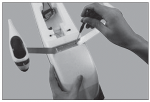
Assembly
- Install the landing gear with PA2.5*10mm screws.
- Fix the landing gear cover in place with Double-sided adhesive.
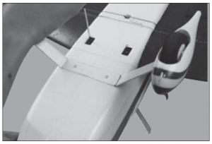
- Install wing struts with PA2.5*8mm screws.
- Fix wing strut cover with foam glue.
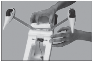
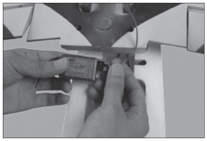
- Connect the aileron servos with Y wires.
- Install the lower wing with PA2.3*20mm screws.
- Install side wing struts with M2*6mm screws.
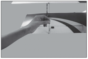
- Put the upper wing on wing struts as shown.
- Fix the upper wing with M2*6mm screws.
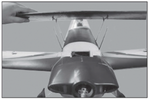
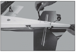
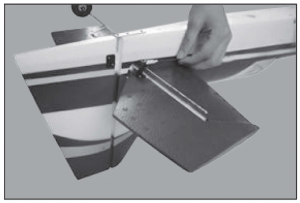
- Insert the horizontal stabilizer and vertical stabilizer in place.
- Fix the stabilizers with PA2.3*20mm screw.
- Install tail wheel with PA2*6mm screws.
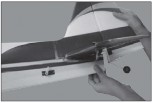
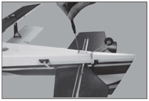
- Install rudder push rod as shown.
- Install elevator push rod as shown.
- Install aileron push rod as shown.
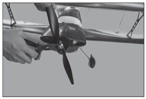
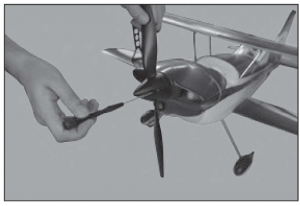
- Install the propeller.
- Install spinner with PA2.5*8mm screws.
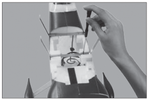
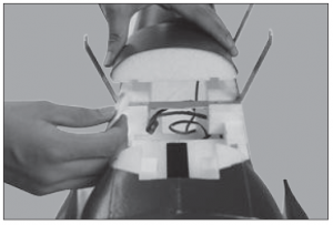
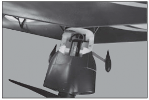
- Put the battery in position.


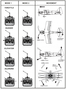
Stick Operation
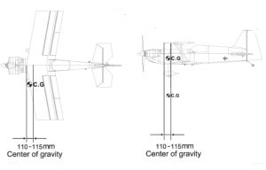
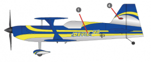
CG And Receiver Assembling
The ideal C.G. position is 110~115mm behind the leading edge measured at where the wing meets the fuselage.In order to obtain the C.G.specified,add weight to the fuselage or move the battery position. Check the C.G. before flying.
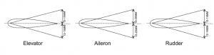
Suggest Control Throw Setting
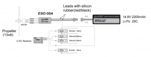
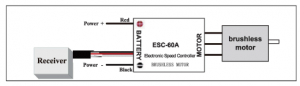
Manual of Brushless Motor Speed Controller
Wiring Diagram:
Programmable Items:
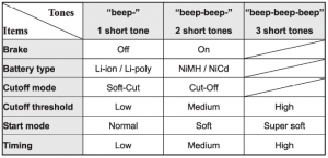
- Brake Setting: Enabled / Disabled, default is Disabled
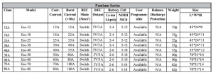
- Battery Type, Li-xx(Li-ion or Li-poly)/ Ni-xx(NiMH or NiCd), default is Li-xx. Protection brush less motor Weight Size L*W*H 19g 45*24*9 19g 45*24*11 22g 45*24*11 25g 45*24*11 35g 55*28*12 60g 70*31*14 60g 70*31*14 62g 70*31*14 62g 70*31*14
- Low Voltage Protection Mode(Cut-Off Mode): Soft Cut-Off (Gradually reduce the output power) or Cut-Off (Immediately stop the output power). Default is Soft Cut-Off.
- Low Voltage Protection Threshold(Cut-Off Threshold): Low/ Medium/ High, default is Medium.♦ When NOT using balance discharge monitoring and protection function (i.e. Not plugging the balance charge connector into the BDMP socket on the Guard series ESC, the ESC only monitors the voltage of the whole battery pack)1) For lithium batteries, the number of battery cells is calculated automatically. Low/ medium / high cutoff voltage for each cell is: 2.6V/2.85V/3.1V. For example: For a 3 cells lithium pack, when “Medium” cutoff threshold is set, the cut-off voltage will be: 2.85*3=8.55V.2) For nickel batteries, low/ medium / high cutoff voltages are 0%/45%/60¾ of the startup voltage (i.e. the initial voltage of battery pack), and 0% means the low voltage cut-off function is disabled. For example: For a 10 cells NiMH battery, fully charged voltage is 1.44*10=14.4V, when “Medium” cut-off threshold is set, the cut-off voltage will be:14.4*45%=6.5Vo When using balance discharge monitoring and protection function (i.e. Plugging the balance charge connector on batterypack into the BDMP socket on the Guard series ESC, the ESC monitors not only the voltage of the whole battery pack but also the voltage of each cell). For lithium battery, low/ medium / high cut off voltage for each cell is: 2.6V/2.85V/3.1V. When the voltage of any cell in battery pack is lower than the cut-off threshold, the protection function is activated.
- Startup Mode: Normal /Soft /Super-Soft, default is Normal. Normal is preferred for fixed-wing aircraft. Soft or Super-soft are preferred for helicopters. The initial acceleration of the Soft and Super-Soft modes are slower in comparison, usually taking 1 second for Soft startup or 2 seconds for Super-Soft startup from initial throttle advance to full throttle. If the throttle is closed (throttle stick moved to bottom) and opened again (throttle stick moved to top) within 3 seconds of the initial startup, the restart-up will be temporarily changed to normal mode to get rid of the chances of a crash caused by slow throttle response. This special design is very suitable for aerobatic flight when quick throttle response is needed.6. Timing, Low/ Medium/ High, default is Low. Note2 Usually, low timing value can be used for most motors. We recommend the Low timing value for 2 poles motor and Medium timing value for motors with more than 6 poles to get a high efficiency. For higher speed, High timing value can be chosen.Note2: After changing the timing setting, please test your RC model on ground prior to flight! Begin
Begin To Use Your New ESC
Please start the ESC in the following sequences:
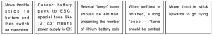
- Move the throttle stick to the bottom position and then switch on the transmitter.
- Connect the battery pack to the ESC, the ESC begins the self-test process, a special tone” . 123″ is emitted, which means thevoltage of the battery pack is in normal range, and then N “beep” tones will be emitted, means the number of lithium battery cells. Finally a long “beep——” tone will be emitted, which means self-test is OK, the aircraft/helicopter is ready to go flying.• If nothing is happened, please check the battery pack and all the connections;Manual of Brushless Motor Speed Controller• If a special tone ” Ji !;<5712″ is emitted after 2 beep tones (“beep-beep-“), means the ESC has entered the program mode, it is because the throttle channel of your transmitter is reversed, please set it correctly;• If the very rapid “beep-beep-, beep-beep-” tones is emitted, means the input voltage is too low or too high, please check your battery’s voltage.
- “VERY IMPORTANT !” Because different transmitter has different throttle range, we strongly suggest you using the “Throttle Range Setting Function” to calibrate throttle range. Please read the instruction on page 4——“Throttle Range Setting”.
Alert Tone
- Input voltage is abnormal: The ESC begins to check the voltage when the battery pack is connected, if the voltage is not in the acceptable range, such an alert tone will be emitted: “beep-beep-, beep-beep-,beep-beep-” (Every “beep-beep-” has a time interval of about 1 second. )
- Throttle signal is abnormal: When the ESC can’t detect the normal throttle signal, such an alert tone will be emitted: “beep-, beep-, beep-“. (Every “beep-” has a time interval of about 2 seconds)
- Throttle stick is not in the bottom position: When the throttle stick is not in bottom (lowest) position, a very rapid alert tone will be emitted: “beep-, beep-, beep-“. (Every “beep-” has a time interval of about 0.25 second.)
Protection Function
- Abnormal start up protection: If the motor fails to start within 2 seconds of throttle application, the ESC will cut-off the output power. In this case, the throttle stick MUST be moved to the bottom again to restart the motor. (Such a situation happens in the following cases: The connection between ESC and motor is not reliable, the propeller or the motor is blocked, the gearbox is damaged, etc.)
- Over-heat protection: When the temperature of the ESC is over 110 Celsius degrees, the ESC will reduce the output power.
- Throttle signal loss protection: The ESC will reduce the output power if throttle signal is lost for 1 second, further loss for 2 seconds will cause its output to be cut-off completely.
Program ExampleSetting “Start Mode” to “Super-Soft”, i.e. value #3 in the programmable item #5
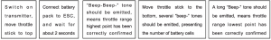
1. Enter Program ModeSwitch on transmitter, move throttle stick to top position, connect battery pack to ESC, wait for 2 seconds, “beep-beep” tone shouldbe emitted. Then wait for another 5 seconds, special tone like •Ji !;<5712″ should be emitted, which means program mode is entered.
2. Select Programmable ItemsNow you’ll hear 8 tones in a loop. When a long “beep——” tone is emitted, move throttle stick to bottom to enter the “Start Mode”
3. Set Item Value (Programmable Value)“Beep-“, wait for 3 seconds; “Beep-beep-“, wait for another 3 seconds; then you’ll hear “beep-beep-beep”, move throttle stick to topposition, then a special tone” Ji f .s i 5″ is emitted, now you have set the “Start Mode” item to the value of “Super-Soft”
4. Exit Program ModeAfter the special tone “Ji f 5 i 5”, move throttle stick to bottom within 2 seconds.
T rou bl e Sh oo f mg
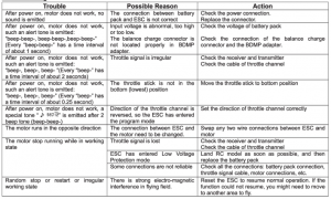
Manual of Brushless Motor Speed Controller
1Throttle range setting: (Throttle range should be reset whenever a new transmitter is being used)
Program the ESC with your transmitter (4 Ste1>s):
- Enter program mode
- Select programmable items
- Set item’s value (Programmable value)
- Exit program mode
1.Enter program mode
- Switch on transmitter, move throttle stick to top , connect the battery pack to ESC
- Wait for 2 seconds, the motor should emit special tone like “beep-beep-“
- Wait for another 5 seconds, special tone like ” J> w112″ should be emitted, which means program mode is entered
2. Select programmable items:
After entering program mode, you will hear 8 tones in a loop with the following sequence. If you move the throttle slick to bottom within 3 seconds after one kind of tones, this item will be selected.
- “beep” brake ( 1 short tone)
- “beep-beep-” battery type (2 short tone)
- “beep-beep-beep-” cutoff mode (3 short tone)
- “beep-beep-beep-beep-” cutoff threshold (4 short tone)
- “beep—–” startup mode (1 long tone)
- “beep—–beep-” timing (1 long 1 short)
- “beep—–beep-beep-” set all to default (1 long 2 short)
- “beep—–beep—–” exit (2 long tone)Note: 1 long “beep—–” = 5 short “beep-“
3. Set item value (Programmable value):
2.Select programmable items:After entering program mode, you will hear 8 tones in a loop with the following sequence. If you move the throttle slick to bottom within 3 seconds after one kind of tones, this item will be selected.
- “beep” brake ( 1 short tone)
- “beep-beep-” battery type (2 short tone)
- “beep-beep-beep-” cutoff mode (3 short tone)
- “beep-beep-beep-beep-” cutoff threshold (4 short tone)
- “beep—–” startup mode (1 long tone)
- “beep—–beep-” timing (1 long 1 short)
- “beep—–beep-beep-” set all to default (1 long 2 short)
- “beep—–beep—–” exit (2 long tone)Note: 1 long “beep—–” = 5 short “beep-”You will hear several tones in loop. Set the value matching to a tone by moving throttle slick to top when you hear the tone, then a special tone ” J> 1515″ emits, means the value is set and saved. (Keeping the throttle stick at top, you will go back to step 2 and you can select other items; Moving the stick to bottom within 2 seconds will exit program mode directly)
How To Programming The ESC With The Dynam Radio
How to enter the programming mode of the Dynam’s brushless ESC with the Dynam 2.4Ghz radio system: (Warning: Please disconnect the motor from the ESC before starting the followingprocedure)
- Turn on the transmitter, then connect battery to the receiver, let the normal auto binding process completed. (Both LED lights on transmitter and receiver should flash rapidly at the same time for this process to succeed)
- Disconnect the receive power; do not turn off the transmitter.
- Move the throttle stick to the top position.
- Toggle the safety switch (on the upper left hand corner of the transmitter). Then make sure the safety switch is at the off position (the tip of the switch is set toward the backof the transmitter)
- Connect battery to the receiver; now you are ready to enter the programming mode (please see the ESC manual for programming instruction).
- If unable to enter the programming mode, please repeat the above procedure again.
Decal

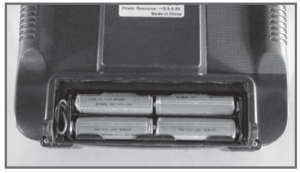
Install the Transmitter Batteries
Install 8 new “AA” batteries in the included transmitter. Check the power level of the batteries and operation of the transmitter by switching the power switch on (upward).The status LEDs at the top of the transmitter will indicate the power level of the batteries . If at any time the status LEDs no longer show green,it will be necessary to replace thebatteries with new ones.
Parts List
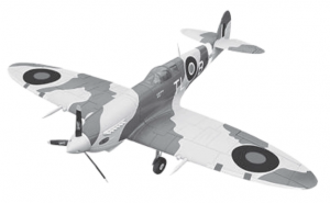
Specification:
Wingspan: – – – – – – -1250mm (49.2in)Overall Length: – – – – – 1235mm (48.6in)Wing Loading: – – – – – 46.5g/dm’Servo: – – – – – – – – 9gx4pcsBattery: – – – – – – – – 14.8V 2200mAh Li-Po, 25CSpeed Controller: – – – – 50A BrushlessMotor Size: – – – – – – – BM3720-KV650 Brushless OutrunnerFlying Weight: – – – – – 1400g ( 49.5oz)
Specification:
Wingspan: – – – – – – – 1200mm(47in)Overall Length:- – – – – 1010mm(40in)Wing Loading: – – – – – 40.5g/dm2Servo:- – – – – – – – – 9gx4pcsBattery:- – – – – – – – 11.1 V 2200mAh Li-Po ,20cSpeed Controller:- – – – 30A brushlessMotor Size: – – – – – – – 850Kv Brushless OutrunnerFlying Weight:- – – – – 1150g(40.6oz)
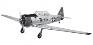
Specification:
Wingspan: – – – – 1370mm (54in)Overall Length: – – – 895mm (35.2in)Wing Loading: – – – -44.69/dm’Servo: – – – – – -9gx4pcsBattery: – – – – – 11.1V 2200mAh Li-Po, 25cSpeed Controller: – – -30A BrushlessMotor Size:- – – – 900KV Brushless OutrunnerFlying Weight: – – – -12509 ( 44.2oz)
www.dynam-rc.cn

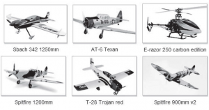
New Products
► Airplanes – Trainer – Warbirds – Sports -Scales – Ducted Fan Planes – 131ider► Helicopters► Re Electronics► Power Systems► Rotor Blade► Acoesso ri es
Read More About This Manual & Download PDF:
Dynam Devil 3D DY8954 Instruction Manual – Dynam Devil 3D DY8954 Instruction Manual –
[xyz-ips snippet=”download-snippet”]