![]()
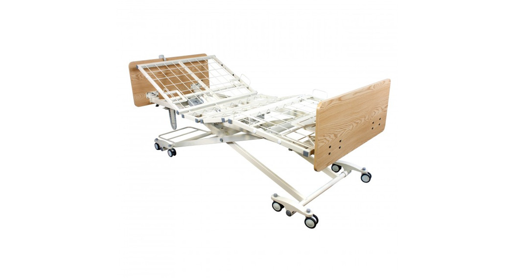
Reorder No. 12002Long-TermCare BedD200User Manual
![]() Manufactured for: Dynarex Corporation 10 Glenshaw Street Orangeburg, NY 10962 USA • www.dynarex.com Made in China
Manufactured for: Dynarex Corporation 10 Glenshaw Street Orangeburg, NY 10962 USA • www.dynarex.com Made in China
![]() WARNINGS
WARNINGS
- Read all instructions before assembling or using the bed.
- DO NOT exceed the maximum weight limit of the bed.The maximum safe working load (SWL) of the bed is 450 lb. The suggested patient weight is 400 lb. but varies based on the accessories on the bed.
- The beds are intended for users who fully understand the content of this manual and is not intended for use by children.
- DO NOT operate your bed until it is fully assembled and checked. To avoid injury, DO NOT attempt to remove the bed from the carton without assistance.
- DO NOT use accessories that are not designed or approved for use with the bed.Use only Dynarex approved parts and accessories.DO NOT make modifications to the bed without authorization from the manufacturer.Doing so will void the warranty. Serious harm or death may result from the use of improper parts or accessories.
- The bed is NOT a transport device. The wheels on the bed are for positioning the bed only.
- Ensure that the casters of the bed are locked at all times to prevent unintended bed movement. The bed should only be unlocked when the bed is moved. If the bed is left unlocked unintended movement may occur which may cause damage to the resident or property damage.
- Moving the bed while the caster locks are engaged may damage the bed or the floor. Ensure all the casters are unlocked prior to moving the bed.
- Never permit more than one person on the bed at one time.
- Ensure that the individual is properly positioned. The body weight must be evenly distributed over the sleeping surface. Nobody part should protrude outside the sleep surface. Caution should be used when transferring the individual to and from the bed.
- ALWAYS keep hands and feet away from the bottom of the bed and any moving parts to avoid injury. Due to the low bed clearance, extreme caution should be used as under-bed space and/or moving parts can create crush or pinch points.
- DO NOT operate the bed with any items under the bed.
- ONLY use appropriate mattresses and ALWAYS adjust the mattress retainer system accordingly to ensure the mattress is fixed in place. The mattress must fit the frame properly to avoid any entrapment issues. The wrong size mattress may cause serious harm or death.For more information about entrapment, visit https://www.fda.gov/media/71460/download.
- Inspect the casters every six months to check for tightness and wear.
- DO NOT, under any circumstances, cut or remove the ground prong from any plug. Some devices are equipped with three-prong (ground) plugs for protection against possible shock hazards. Where a two-prong wall receptacle is encountered, it is the personal responsibility and obligation of the customer to contact a qualified electrician to have the two-prong receptacle replaced with a properly grounded three-prong wall receptacle in accordance with the regional and national regulations.If you must use an extension cable, use ONLY a three-wire extension cable having the same or higher electrical rating as the device being connected.
- Cables should be routed and secured properly to ensure they are not damaged during normal operation. DO NOT use if any cable is cut, frayed, or loosely connected to the device. Cables may be damaged by inappropriate handling, e.g. by kinking, shearing, or other mechanical damages. The cables are only replaceable by authorized Dynarex service personnel.
- When moving the bed ensure the power cord and pendants are secured.Ensure that the casters do not roll over the cables.
- DO NOT attempt to open the pre-sealed actuator or obtain local service, for it will VOID the warranty and might result in damage. Consult your dealer or manufacturer for further information.
- This bed is not intended to be used in an oxygen-rich environment.
- DO NOT allow any part of the bed to become wet or submerged in water.
- DO NOT use near fire or explosive gases.
- The hand pendant cord may be a source of entanglement.Patients with decreased mental acuity should not have access to the pendant as serious harm or death may result. An optional staff control embedded into the footboard is available.
- For every 2 minutes of continuous use of the actuator, the bed actuator must not be in use for 18 minutes.
![]() WARNINGS (Continued)
WARNINGS (Continued)
WHEN USING RAILS OR ASSIST BARS:
Before operating, ensure that the bed rails/bars are assembled and installed correctly as instructed.
DO NOT apply side pressure to the bed rails/bars as it deforms or damages the bed and/or bed rails/bars. Serious harm or death may result from improper use of the bed rails/bars.
DO NOT use the bed rails/bar as a push handle for moving the bed. This could deform or break the bed rails.
- DO NOT use the bed rails/bar if the proper installation cannot be achieved. Contact your dealer or manufacturer.
DECLARATION – ELECTROMAGNETIC EMISSIONS
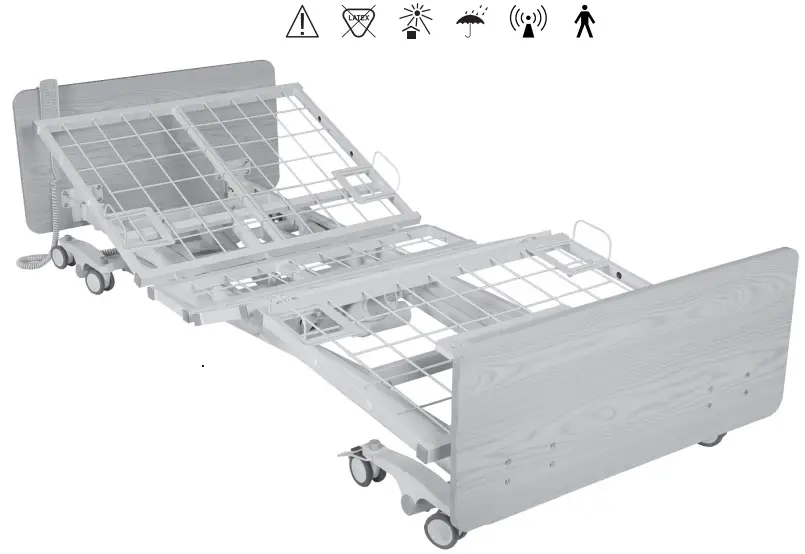
The D200 Long-Term Care Bed is intended for use in the electromagnetic environment in which radiated RF disturbances are controlled. The customer or the user of the D200 Long-Term Care Bed can help prevent electromagnetic interference by maintaining a minimum distance between portable and mobile RF communications equipment (transmitters) and the D200 Long-Term Care Bed and according to the maximum output power of the communications equipment. Please contact Dynarex at QA.[email protected] for more information and manufacturer technical specifications.Special considerations should be given to the proximity of the D200 Long-Term Care Bed and patients who have a cardiac pacemaker, implanted defibrillator, or other implanted metallic or electronic device, because this may cause electrical interference or death. Contact Dynarex QA.[email protected] for manufacturer electromagnetic interference technical specifications.![]() Interference to electronic equipment may occur In the vicinity of devices marked with this symbol:
Interference to electronic equipment may occur In the vicinity of devices marked with this symbol:
TECHNICAL SPECIFICATIONS
| OPERATING RANGE | Bed Height | 7.8″-30″ |
| Back Rest Angle | 0°-65° | |
| Knee Break Angle | 0°-35° | |
| Additional Manual Leg Lift | N/A | |
| TrendelenburglReverse Trendelenburg | N/A | |
| Auto Contour | Yes | |
| WEIGHTLIMIT | Weight Capacity | 470 lb. |
| Safe Working Load (SWL) | 450 lb. | |
| WEIGHTS &DIMENSIONS | Sleeping Surface Dimension (Width • Length – Extension) | 36″ • 80%84%88″ |
| Caster Size | 3″ | |
| Gross Weight | 231 lb. | |
| Net Weight | 188 lb. | |
| ELECTRICS | Power Supply (V/PH/Hz) | 100-240V/1pIV50-60Hz |
| Power Consumption (Max) | 230 W | |
| Number of Motors | 3 | |
| Protection Class | IPX4 | |
| Insulation Class | II Type B | |
| Duty Cycle | Interruption 10%, Max. 2 min./18min, | |
| Battery backup | Yes, optional | |
| ENVIRONMENT | Operating Temperature | 40°F-105°F (5°C-40°C) |
| Storage Temperature | 15°F-120°F (-10°C-50°C) | |
| Operation & Storage Humidity | 20%-80% | |
| Operation & Storage Atmospheric Pressure | 700-1060 hPa | |
| Operation & Storage Altitude | s 3000 m | |
| Noise Level | < 50db(a) |
ASSEMBLY INSTRUCTIONS
UNPACKING THE BED
- Unpack the components from the shipping cartons.
- Remove any black zip ties holding the components to the Bed Assembly. White zip ties should not be removed.
- Upon unpacking your bed, the package should contain all the components shown below.
- Inspect the bed components for damage. If the bed is damaged, do not use the bed and contact the manufacturer.

ASSEMBLY INSTRUCTIONS (Continued)
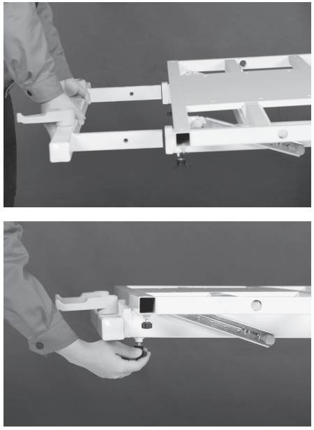
ASSEMBLING THE HEADBOARD BRACKETS TO THE BED
- With the bed raised to its highest position, step on the locking levers to lock the casters on the foot end of the bed.
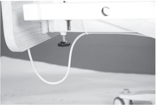
- Turn and loosen the black knob on the underside of the bed assembly insertion slots on the head side of the bed.
- Slide one of the headboard brackets into the slot (the headboard brackets are shorter than the footboard brackets). Tighten the black knob to secure the bracket in place.
- Repeat the same procedure for the other headboard bracket.
- Headboard brackets should not be used for length extension. They should always be fully inserted in the slots.
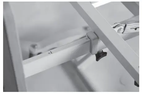
ASSEMBLING THE FOOTBOARD BRACKETS TO THE BED
- Turn and loosen the black knob on the underside of the bed assembly insertion slots on the foot side of the bed.
- Slide one of the footboard brackets into the slot.Tighten the black knob to secure the bracket in place.
- Repeat the same procedure for the other footboard bracket.

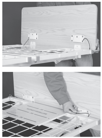
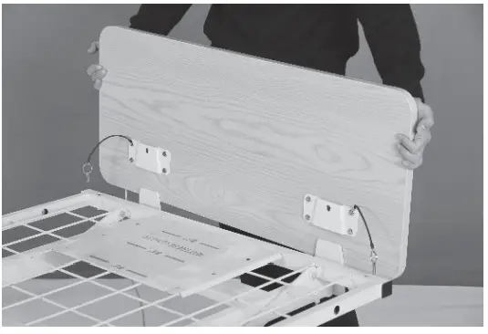
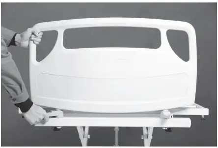
2.3 ASSEMBLING THE HEADBOARDS/ FOOTBOARDS ONTO THE BED
- With the mounting plates on the headboard facing the bed, slide the mounting plate groove onto the headboard mounting bracket’s vertical support.
- Insert the lock pin through the mounting plate into the headboard to secure the headboard in place.Repeat on the other mounting plate.
- Repeat the same procedure for the footboard installation.
INSTALLING THE WIDTH MATTRESS RETAINERS
- Locate the mounting holes for the mattress retainers in the bed deck. Align and insert the mattress retaining wires through the pre-cast holes.
- Ensure the mattress retainer is flat against the bed deck.
- Repeat the procedure for all four mattress retainers.

INSTALLING THE BED-END MATTRESS RETAINER
- Locate the mounting holes for the bed-end mattress retainer in the foot side of the bed deck.
- Align and insert the mattress retaining wires through the pre-cast holes.
- Ensure the mattress retainer is flat against the bed deck.
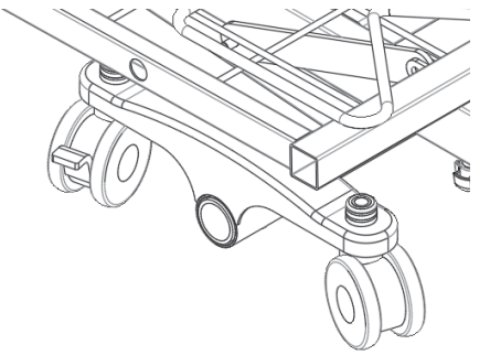
INSTALLING THE WALL BUMPER BAR
- Remove the nuts and bolts from the two round clamps on the caster legs at the head of the bed.
- Align the mounting holes of the bumper bar with those on the clamps.
- Re-insert the bolts through the clamps and tighten them with nuts. Ensure the bumper bar is positioned parallel to the ground.
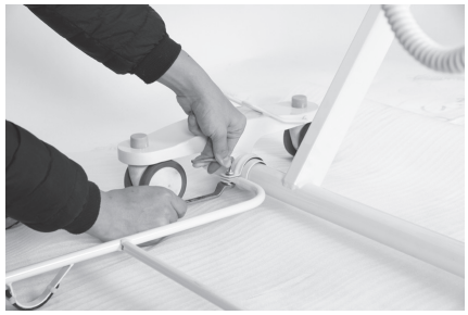
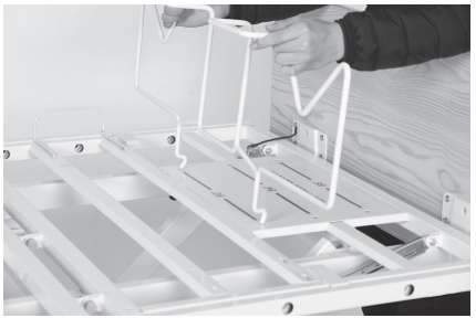
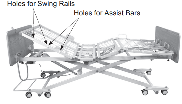
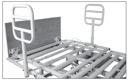
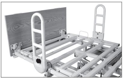
INSTALLING THE RAILS OR ASSIST BARS
- Before installing the rails or bars, the bed should be in a flat position.
- Unclip the metal snap ring and remove the metal pins from the rail mounting brackets.

- Remove cover for the appropriate holes.Holes for Swing Rails
- Place the rail bracket onto the edge of the bed decking. Align the rail bracket mounting holes with the bed deck mounting holes. Slide the U-shaped insert into the assist bar bracket.
- Re-insert the metal pins from the outside edge of the bed through the mounting holes and secure them with the snap rings on the inside edge of the bed.Make sure the snap rings are positioned in the groove of the metal pins.
- If the bed rail or bar has additional Allen screws, tighten the Allen screws next to the metal pins.
- Repeat the same procedure to install the other rail.


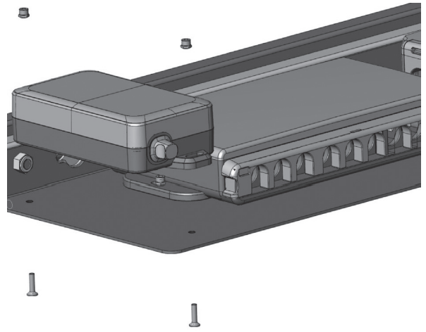
CONTROL BOX CONNECTIONS
Upon opening the control box, each motor connection port is numbered for ease of identification.
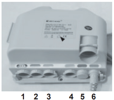
- Battery Backup Port
- Backrest Motor
- Knee-break Motor
- Bed Lift Motor
- Spare
- Port for hand pendant or staff control
INSTALLING THE FOOTBOARD WITH STAFF CONTROL
- Unplug the bed from the outlet prior to installation.
- Mount the footboard with built-in staff control.
- Open the locking lid of the control box to expose the port connections.
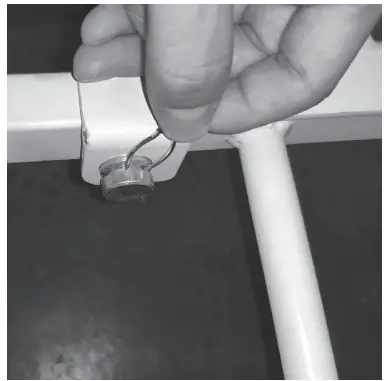
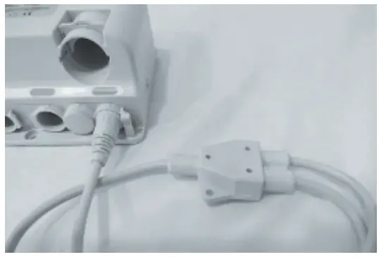
- Disconnect the hand pendant connection to the control box and replace it with a cable splitter.
- Lift up the lid on one of the splitter ports and plug in the hand pendant. Push down the lid to secure the connections.
- Repeat the procedure and plug the cord from the staff control footboard into the other splitter port.Use the included zip ties to secure the cord to the bed frame. Ensure the cord does not interfere with the bed operation.
- Reinstate the control box locking lid. There should be an audible click.
- Plug the bed into an appropriate outlet and test functions to ensure all functions work correctly.


INSTALLING THE BATTERY BACKUP
- Unplug the bed when installing the backup battery.
- Affix the battery backup with nuts and bolts to the side of the control box, on the same holding plate.
- Open the control box locking lid by pressing in the sides and lift it up, to expose the connection parts.
- Connect the backup battery cord to the control box. The connection port is indicated with a battery symbol above.
- Close the locking lid, there should be an audible click, switch the power supply back on.
INSTALLING THE COMPOSITE HEAD & FOOTBOARDS
- Raise the bed to its highest position and lock the bed in place.
- Turn and loosen the two black turn knobs on the underside of the Bed Assembly insertion slots.
- Slide the footboard frame into the slots (the footboard frame is longer than the headboard frame)The plastic levers mounted on the footboard frame should be on top. Tighten the black turn knobs.
- Ensure the two plastic levers on the footboard frame point away from the bed.
- Insert the footboard squarely through the plastic levers into the footboard frame.
- Rotate the plastic levers until they are paralleled with the footboard, pointing to the sides of the bed.This will lock the footboard in place.
- Repeat the same procedure for the headboard installation.

EQUIPMENT OPERATION
- POSITIONING THE BED To position, the bed, unlock the casters. Once the bed is in its desired location, lock all the casters by pushing on the locking levers.
- EXTENDING THE LENGTH OF THE BED FROM 80″ TO 84″ OR 88″ 1. Loosen the two black knobs located on the underside of the bed frame securing the footboard frame. (Refer to Section 2.3 on page 6.)2. Pull the footboard frame away from the bed squarely with both hands to the required length.The distances are marked on the footboard frame, 80″, 84″, and 88″. Tighten the securing knobs once the desired length is set.3. Adjust the bed end mattress retention frame to the required position. The extension lengths are marked on the bed platform.
- USING THE HAND PENDANTThe UP arrow (▲) indicates raising the corresponding parts of the bed. The DOWN arrow (▼) indicates lowering the corresponding parts of the bed.
EQUIPMENT OPERATION (Continued) - OPERATING THE BED RAILSMETAL SWING RAIL(REORDER NUMBER 12950)Raise Bed Rail: Pull the bed rail upwards until the rail is securely locked in place.Lower Bed Rail: Squeeze the release lever at the bottom corner of the bed rail and slowly lower the bed rail to its lowest position.COMPOSITE SWING RAIL(REORDER NUMBER 12951)Raise Bed Rail: Pull the bed rail upwards until the rail is securely locked in place.Lower Bed Rail: Press the release button and slowly lower the bed rail to its lowest position.
 EQUIPMENT OPERATION (Continued)
 COMPOSITE SWING RAIL(REORDER NUMBER 12951)Raise Bed Rail: Pull the bed rail upwards until the rail is securely locked in place.Lower Bed Rail: Press the release button and slowly lower the bed rail to its lowest position.
Q ASSIST BAR(REORDER NUMBER 12952)Parallel Q Assist Bar Alignment: Lift up and rotate the bar until it is parallel to the bed edge. Lower the bar and ensure it is securely locked in place.Perpendicular Q Assist Bar Alignment: Lift up and rotate the bar until it is perpendicular to the bed edge lower the bar and ensure it is securely locked in place.
PIVOT ASSIST BAR(REORDER NUMBER 12953)Raise Assist Bar: Pull the bar upwards until the bar is securely locked in place. Ensure the release button is engaged.Lower Assist Bar: Pull the release knob and slowly lower the bar to its lowest position.
TROUBLESHOOTING GUIDE
| SYMPTOMS | POSSIBLE FAULTS | POSSIBLE SOLUTIONS |
| Bed idles when hand pendant buttons are pressed. | Adjustment may be at the maximum or minimum position.The power cord is not connected or damaged.Hand pendant or actuator connectors are loose.The load is too heavy. | Check if the other buttons are working.Ensure the power cable is properlyconnected to the electrical socketand the bed.Ensure tight connection of all connectors to the control box.Ensure the load weight is within thedesignated capacity. Reduce theload. |
| Adjustment via hand pendant or Staff Control only partially occurs and stops. | The bed may be overloaded.The bed may be constrainedfrom moving.Actuators connection maybeloose or damaged.Thermal shut down may haveoccurred.If battery backup is installed,the battery may be low. | Ensure the load weight is within thedesignated capacity. Reduce theload.Check for obstructions.Ensure actuator is properly securedto the bed.Wait at least 20 minutes before trying the functions again. The bed is intended to be used for 2 min every20 min.Plug bed into the appropriate powersource. |
| Bed not responding to hand pendantor Staff Control. | The lockout function may be engaged.Cables may be loose.Thermal shut down may haveoccurred. | Ensure that the lockout function is notengaged on the Staff Control.Ensure all cables are fully inserted.Ensure the bed is plugged intoappropriate outlet.Unplug the bed for 60 seconds andplug back in.Wait at least 20 minutes beforetrying the functions again. The bed isintended to be used for 2 min every20 min. |
TROUBLESHOOTING GUIDE (Continued)
| Casters/Brakes are noisy or stiff. | Debris or fluff in bearings. | Clean or replace casters. |
| Noisy or dry sound from pivot points. | Needs lubrication. | Lubricate your bed. |
| Unusual noise from the actuator. | The actuator is worn, damagedor spindle is bent. | Replace the actuator.Contact your supplier. |
| Head/Footboard unstable. | Head/Footboard frames arenot tightly secured. | Refer to Assembly Instructions. |
LIMITED WARRANTY
Your Dynarex Product is warrantied to be free of defects in materials and workmanship for Fifteen (15) years on structural Steel, Three (3) years on electrical and mechanical, and One (1) year on all other parts and components from the original date of purchase. This item was built to exacting standards and carefully inspected prior to shipment. This warranty is an expression of our confidence in the materials and workmanship of our products and our assurance to the consumer of years of dependable service.
The Warranty shall not apply under the following conditions:
- Problems arising from normal wear
- Problems arising from failure to adhere to the product instructions
- Problems arising from misuse, negligence, accident or improper operation, maintenance, or storage
- Problems arising from modifications or unauthorized repairs, parts or attachments
- Products where the serial number has been removed or defaced
- Problems with non-durable components, such as rubber accessories, casters, and grips, which are subject to normal wear and need periodic replacement
Dynarex shall not be liable for any consequential or incidental damages whatsoever. Dynarex shall repair or replace defective products at its option. The foregoing warranty is exclusive and in lieu of other express warranties, if any, including the implied warranties of merchantability and fitness of a particular purpose. The remedy for any violation of the implied warranty shall be limited to the repair or replacement of the defective product pursuant to the terms contained herein.If you have a question about your Dynarex device or this warranty, please contact an authorized Dynarex dealer.
 SYMBOL GLOSSARYFor an explanation of symbolsused in Dynarex packaging, visitdynarex.com/symbols.php
http://dynarex.com/symbols.php
![]() WARNING:Cancer and Reproductive Harmwww.P65Warnings.ca.gov
WARNING:Cancer and Reproductive Harmwww.P65Warnings.ca.gov
SERVICE RECORD
| DATE | PERFORMED BY | CONDITION REPORT |
SERVICE RECORD
| DATE | PERFORMED BY | CONDITION REPORT |
References
[xyz-ips snippet=”download-snippet”]