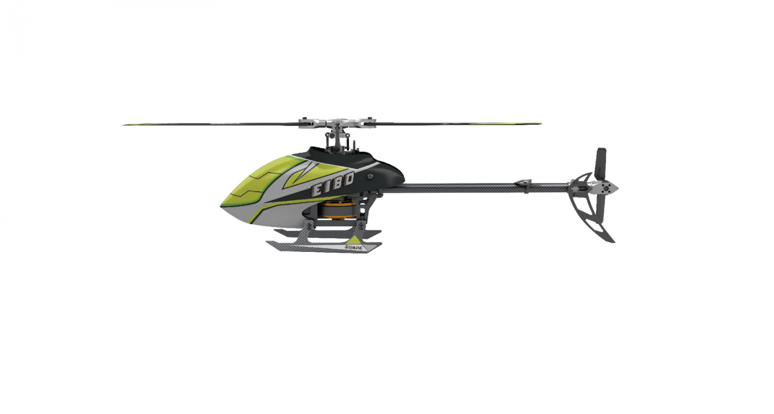
Eachine E180 Helicopter
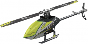
This product is compatible with FUTABA 2.4GHz S-FHSS regulations.Brushless motor, super power, compatible with 3-axis gyroscope and 6-axis gyroscope modes, 3-axis for ultra-stable flight and 6-axis for beginners.
ITEM LIST
|
NO. |
PARTS | QUANTITY |
|
1 |
Gift Box | 1 |
|
2 |
PVC rotective box | 1 |
|
3 |
User Manual | 1 |
|
4 |
Helicopter | 1 |
|
5 |
Transmitter | 1 |
|
6 |
Charger | 1 |
|
7 |
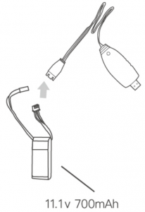
Battery 11.1 v 700mah 30C | 1 |
|
8 |
Cross Screwdriver / Hex Wrench | 1 |
|
9 |
Main Blade | 2 |
|
10 |
Tail Blade | 1 |
|
11 |
Main Gear | 1 |
NOTICE
All instructions, warranties and other collateral documents are subject to change at the sole discretion of our company. For up-to-date product literature, please visit www.eachine.com
WARNING
Read the ENTIRE user manual to become familiar with the features of the product before operating. Failure to operate the product correctly can result in damage to the product, personal property and cause serious injury. This is a sophisticated hobby product. It must be operated with caution and common sense and requires some basic mechanical ability.Failure to operate this product in a safe and responsible manner could result in injury or damage to the product or other properties. This product is not intended for use by children without direct adult supervision. This manual contains instructions for safety, operation and maintenance. It is essential to read and follow all the instructions and warnings in the manual, prior to assembly, setup or use, in order to operate correctly and avoid damage or serious injury.
ADDITIONAL SAFETY PRECAUTIONS AND WARNINGS
- Age Recommendation: Not for children under 14 years. This is not a toy.
- Always operate your model in open spaces away from full-size vehicles. Traffic and people.
- Follow the operation notice, warning and any support equipment (charger, battery, etc.) carefully.
- Keep away from any chemicals; keep children away from any small parts and electrical equipment.
- Always keep away from water, especially for this product don’t have waterproof function; It will be damaged by moisture.
- Never place any portion of the model in your mouth as it could cause serious injury or even death.
- Never operate your model with low voltage transmitter batteries.
INTRODUCTION
This is a super classic helicopter with excellent fight performance. Flybarless design, decrease resistance of rotor head. Quote to aerodynamics, the blades can supply strong power and keep stability. Using new type gyro, compatible with 3D and 6G modes. You can make a variety of stunts by 3D mode; 6G mode is suitable for beginners especially.
After flying this mini helicopter, you will find other mini helicopters which you have flying are eclipsed, This is a incomparable and popularization helicopter. Beginners will find it is easy to fly, masters will find it is interesting. It is worth to be possessed.
This manual with detailed instruction ,will help you learn more about the product Please read it before your flying
HELICOPTER PARAMETERS
| Length | 400 MM |
| Height | 120MM |
| Weight | 297g |
| Length of Main Propeller | 410MM |
| Diameter of Tail Propeller | 73MM |
| Battery Specification | 11.1v 700mah 30C |
| Flight Time | 6-10 Min |
| Main Brushless Motor | 3606 |
| Brushless Tail Motor | 1104 |
WARNING AND THE GUIDE OF BATTERY USAGE
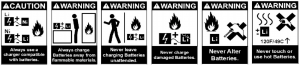
To ensure safety, please use the included standard charger
WARNING: It is recommended to use the original power supply charger when charging, otherwise property damage and injury will occur.
Notice: When it is lower than 11.1V, the lithium battery may be damaged, or it may no longer be charged. When the battery voltage is lower than 11.1V when the aircraft is flying, the power of the aircraft drops significantly. Please immediately land and charge the battery in time.
BATTERY CHARGING
- The user should connect to the power adapter with a USB port or connect to the USB port of computer.
- Connect the USB cable to the power adapter, at the same time the USB charger red light flashes.
- The partial voltage charging head of the battery is connected with the USB cable. At this time, the USB charger’s red light always on and charging is in progress.
- When the USB charger red light is off, charging is completed.

Warning
- To ensure safety, please charge under the supervision of someone.
- Children cannot charge alone, they should charge with the assistance of an adult.
- Please use the original standard charger of this product for charging. The charger of unknown origin may cause a fire and explosion accident.
- It is recommended that users prepare their own 2A current adapter, which will shorten the charging time.
NOTICE BEFORE FLIGHT
- Make sure the battery power is full both for TX and helicopter.
- Before open the power of TX, please make sure the TH. Stick at the bottom and the switch of TH.HOLD and 3D mode in back position (back cover direction).
- Make sure the TX has paired with helicopter ,or please pair them again.
- Please open TX first, then connect the battery with the RX board on helicopter to pair with TX. When close, please cut the power of helicopter first, and then turn off the TX.
- Keep away from crowd, cars, high-tension towers and pond. Then you can start your flying.
BIND WITH TRANSMITTER
You buy the original model The pairing has been reset before factory. If you need to pair again, please comply with the following steps.
- First open the transmitter, make sure the throttle joystick is in the bottom position, 3D1 IDLE switch in the OFF position
- Take down the canopy for touching the code switch.
- Charge the helicopter, the red lamp flashes slowly, press the code button for 1 second, then the red lamp will go out and get ready for pairing.
- When the red and blue lights turn solid, the pairing has been successful.
- Ensure there are no other the transmitter of the same type at work to avoid interference.
Tips: This product is compatible with all FUTABA 2.4GHZ S-FHSS transmitter.Notice: If the throttle of the transmitter has not been positioned at the lowest position with the throttle switch and 3D mode switch turned on, the transmitter will beep to prompt you that it fails to proceed to pair.
Notice:
- When the transmitter is turned on, the throttle hold switch is in the ON state, and the transmitter beeps . The switch should be turned back to the OFF position.
- When the transmitter is turned on, the 3D switch is in the ON state, and the transmitter will beep. The switch should be turned back to the OFF position.
- When transmitter is turned on, the throttle stick is not in the lowest position, and the transmitter will beep. The throttle stick should be pulled down to the lowest position.
THROTTLE CURVE AND PITCH CURVE
| Throttle Curve |
Position |
Normal |
3D Idle |
|
1 |
0 |
90 |
|
|
2 |
70 |
90 |
|
|
3 |
70 |
90 |
|
|
4 |
70 |
90 |
|
|
5 |
70 |
90 |
|
Throttle Curve |
Position |
Normal |
3D Idle |
|
1 |
0 |
90 |
|
|
2 |
70 |
90 |
|
|
3 |
70 |
90 |
|
|
4 |
70 |
90 |
|
|
5 |
70 |
90 |
The above information is for your reference only, you can set the parameters to your demand.
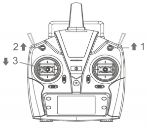
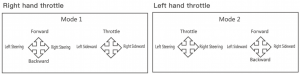
INITIAL FLIGHT
If you are not familiar with the control of the E180 , take a few minutes to get familiar with them and then try your first flight.
Throttle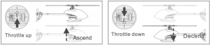
Rudder
Elevator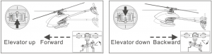
Aileron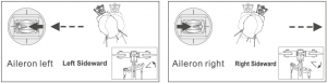
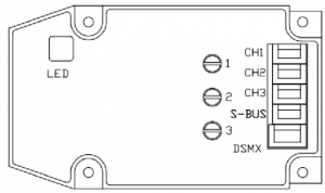
RECEIVER INTERFACE DIAGRAM
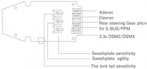
Notes: 3.3V is suitable for DSM receiver and 5V is suitable for FUTABA (S BUS) J receiver.
ABOUT THE TRANSMITTER
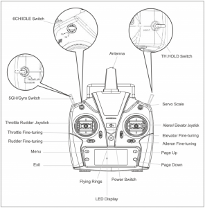
This transmitter supports CCPM 120 degree helicopter dedicated transmitter,with 3D 6G switching high/ low rudder capacity for two joystick modes, flameout switch (TH.HOLD) and other modes, large screen LCD display multi-function transmitter.
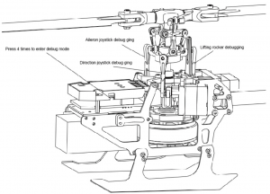
FLIGHT BATTERY INSTALLMENT
- Debugging pitch of threadExplanation: The product has passed the inspection before leaving the factory, the user needs to re-adjust the pitch of thread after replacing the steering gear or related accessories.To ensure safety, disconnect the main motor power cord during commissioning to avoid personal injury caused by motor rotation during commissioning.The user comes with a special pitch of thread ruler for helicopters that can be adjusted more accurately.First, bind the aircraft to the code, and the transmitter in 6G self stabilization mode.Press the code matching key on the flight control board 4 times, the mainboard will flash red quickly and enter the debugging mode.Use the transmitter to control the aileron rocker, lift rocker, and direction rocker for debugging until the swashplate is balanced and the blades are at O pitch of thread After the debugging is completed, press the motherboard link key to exit the debugging, the motherboard will resume the red light and the blue light will be on, then you can fly
- Sensitivity adjustmentUsers can adjust different lock perception according to their own needs, use a flat-blade screwdriver to adjust, turn clockwise to increase the lock perception, and turn counterclockwise to decrease the lock perception1 Lock tail sensitivity 2 Swashplate perception 3 Swashplate sensitivity
TROUBLESHOOTING
| Problem | Cause | Solution | |
| 1 | LED on receiver flashes constantly with no responses after connecting batteries to transmitter. | Transmitter is not bound to receiver.Pairing of the transmitter and receiver failed . | Re-pair (Refer to P.5, Programming your Transmitter) |
| 2 | The helicopter has no response after connecting batteries to receiver. | Check whether the transmitter and receiver connecting to power; check the voltage of transmitter and receiver; Battery pole flake contact is not good. | Open the transmitter, make sure the batteries connecting is good Replace and charge transmitter batteries Make sure the battery pole flake contact is good. |
| 3 | When push the throttle pole, the rotor do not rotate and the LED on Receiver flashes cons tantly. | Low battery voltage; batteries connection is not good. | Replace and charge the batteries, reconnect the batteries to the receiver board. |
| 4 | Helicopter takes off immediately, once the batteries and receiver connected. | Didn’t put the throttle to the lowest | Put the throttle pole at the lowest position before open the transmitter. |
| 5 | Helicopter vibrates or shakes in flight. | Damaged frotor blades and lateral axis blade grips too tight causing the movement of the main rotor isn’t smooth. | Change the main rotor blades, and lateral axis Loosen the blade grips properly. |
| 6 | Main rotor blades are shaking in flying. | Lateral axis is bent Latreral axis screw is not tight .There are some debris in the servo, causing shakes .The loose between the swashplates.Deformed or damaged t ail rotor blades. | Replace the lateral axis. Tighten the lateral axis screw. Change the Bearing.Remove the servo, and clear debris.Compress the swash plates. change the tail rotor blades. |
| 7 |
The sound of the main rotor becomes smaller. |
Low battery voltage of helicopter. | Charge the battery or change a fully charged battery. |
| 8 |
Helicopter has no reaction or can not fly smoothly. |
Failure of binding | Rebind the helicopter and transmitter, make sure you place the helicopter static level next to the transmitter. |
| 9 |
3D/6G model helicopter appeared yaw |
Swashplate servos not back in to mid-position or damage |
Length adjustment rod, so that the vertical spindle swashplate Replace the servo |
| 10 | Helicopter yaw occurs in 6G mode, | Helicopters hover need to reconfigure | Reference helicopter 6G mode setting |
| 11 | Helicopter took off spin to the left. | Tail motor power shortage loose bladesTail motor damage | Check with the tail rotor blades and the motor shaft, If loose replacement tail rotor blade.Motor damage Replace the tail motor. |
| 12 | Helicopter power is turned supreme speed govermor electric sound | Brushless speed governor fault or poor contact | Check the connectors replace speed governor |
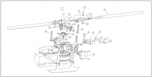
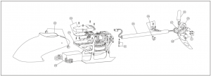
EXPLODED VIEW

ACCESSORY LIST
|
NO. |
PARA NAME |
QUANTITY |
|
1 |
Rotor Head Set |
1 |
|
2 |
Horizontal Axis Group |
2 |
|
3 |
Rotor Clip Set |
1 |
|
4 |
Paddle Group |
2 |
|
5 |
Link Group |
1 |
|
6 |
Swash Plate Group |
1 |
|
7 |
Lower Link Group |
2 |
|
8 |
Rudder Unit |
1 |
|
9 |
Spindle Group |
2 |
|
10 |
Servo Pressure Plate Group |
1 |
|
11 |
Main Motor Unit |
2 |
|
12 |
Bearing Set |
1 |
|
13 |
Main Rack Group |
1 |
|
14 |
Big Gear Set |
1 |
|
15 |
Flight Control Motherboard |
2 |
|
16 |
Governor Group |
1 |
|
17 |
Landing Gear Group |
2 |
|
18 |
Chassis Group |
1 |
|
19 |
Tailstock Group |
1 |
|
20 |
Tail Motor Unit |
2 |
|
21 |
Chassis Group |
1 |
|
22 |
Rear Wing |
1 |
|
23 |
Screw Set |
1 |
|
24 |
Battery |
1 |
|
25 |
USB Charger Set |
1 |
|
26 |
the transmitter Unit |
1 |
Notice for beginners:
- Please fly you models with guidance in the first time.
- Before fly the models, you need to understand all the function of the transmitter and reaction cause by the rockers.
- Don’t use 3D mode hurried. Practice flying and hovering flight under 6G mode until you are familiar with it. Then you can practice flying and hovering flight under 3D mode. When you are familiar with these two modes you can practice! inverted flight with guidance.
- Practice hovering flight of inverted flight to lay a foundation for making more brilliant flying.
- This model is not a toy. To avoid damage, please take a simulated flight through computer before 3D flying.
ACCESSORIES LIST
| Part No: 2.32.01.E180·001Part Name: Rotor Head Set | Part No: 2.32.0 1. E1 80·002Part Name: horizontal axis Set | Part No: 2.32.01. El 80·003Part Name: Rotor Clip Set | Part No: 2.32.01. El 80·004Part Name: Rotor Blade Set |
 |
 |
 |
 |
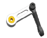
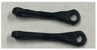
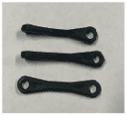
| Part No: 2.32.01.E180·005Part Name: Upper Rocker Arm Set | Part No: 2.32.0 1. E180·006Part Name: Upper Linkage Se | Part No: 2.32.01. El 80-007Part Name: Swashplate Set | Part No: 2.32.01. El 80·008Part Name: Under Linkage Set |
 |
 |
 |
 |
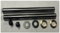
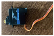
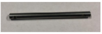
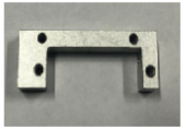
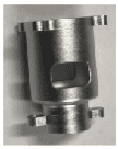
| Part No: 2.32.01.E180·009Part Name: Servo Set | Part No: 2.32.0 1. E180·0 10Part Name: Main Shaft Set | Part No: 1.02.07. El 80·033Part Name: Elevating Servo Platen Set | Part No: 2.32.01. E180·011Part Name: Main Motor Set |
 |
 |
 |
 |
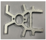
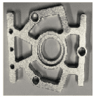
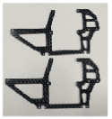
| Part No: 2.32.01.E180·012Part Name: Main frame Bearing Set | Part No: 1.02.07.E180·031Part: Name: Upper Stand Set | Part No: 1.02.07.E180·032Part Name: Under Stand Set | Part No: 2.32.01.E180·01Part Name: Tail Rod Fixing Frame Set |
 |
 |
 |
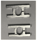 |
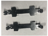
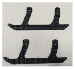
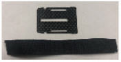
| Part No: 2.32.01.E180·014Part Name: Electronic Pallet Set | Part No: 2.32.01.E180·015Part Name: Landing Skid Bracing Plate Set | Part No: 2.32.01. E1 80·016Part Name: Side Plate Set | Part No: 2.32.01.E180·017Part Name: Landing Skid Set |
 |
 |
 |
 |
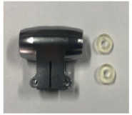
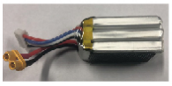
| Part No: 2.32.01.E180·018Part Name: Canopy Fixing Leg Set | Part No: 2.32.01.E180·019Part Name: Canopy Set | Part No: 2.32.01. E1 80·021Part Name: Battery Set | Part No: 2.32.01.E180·022Part Name: Battery compartment Boi1d Set |
 |
 |
 |
 |
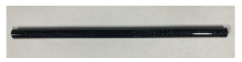
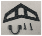
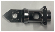
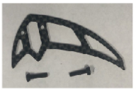
| Part No: 1.02.08.03.E180-001Part Name: Tail Rode Set | Part No: 2.32.01.E180-023Part Name: Horizontal Tail Set | Part No: 1.02.07.E180·023Part Name: Tail Motor Frame Set | Part No: 2.32.01. E180·024Part Name: Vertical Tail Set |
 |
 |
 |
 |
| Part No: 2.32.01.E180·025Part Name: Tail Motor Set | Part No: 2.32.01.E180·026Part Name: Tail Blade Set | Part No: 1.03.04.E180·001Part Name: USB Charger Set | Part No: 2.03.01. E180·001Part Name: Transmitter Set |
 |
 |
 |
 |

[xyz-ips snippet=”download-snippet”]