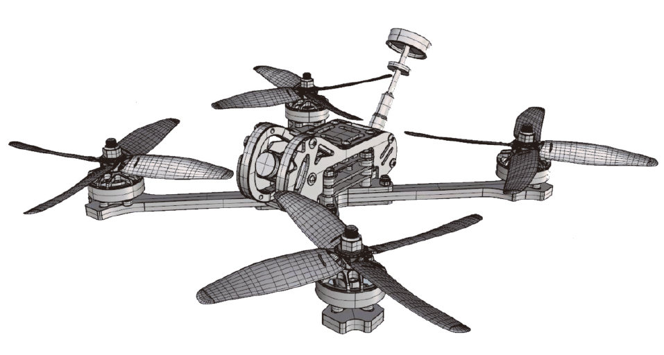
Eachine TYR0109 Racing Drone Quick Start Guide
Package Included:
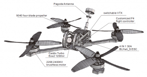
1 x 210mm frame kit2 x 2206 2400KV brushless motor CW2 x 2206 2400KV brushless motor CCW1 x 4 IN 1 30A BLHeli_S ESC1 x Customized F4 flight controller1 x Caddx Turbo Eos2 1200tvl1 x XF5804 5.8G 40CH 0mw/25mw/200mw/600mw switchable VTX1x Pagoda Antenna2 x Battery strap2x 5040 four-blade propeller CW2x 5040 four-blade propeller CCW
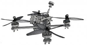
 1.0 Frame kit
 1.0 Frame kit
Wheel base: 210mmFrame arm thickness: 5mmBottom plate thickness: 2mmSide plate thickness: 2mmFrame kit material: 3K carbon fiber & 6065 aluminium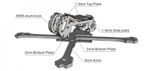
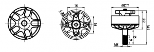
2.0 Motor
Wheel base: 210mmFrame arm thickness: 5mmBottom plate thickness: 2mmSide plate thickness: 2mmFrame kit material: 3K carbon fiber & 6065 aluminiumKV: 2400KVIdle current (Io/10V): 1.35ALipo cell: 3-5SWeight: 31gMax continuous current: 35AMax continuous power: 560WMax thrust: 1180g (4S/5″)Configu-ration: 12N/14PMotor resistance (RM): 0.0536 Ω
Stator diameter: 22mmStator thickness: 6mmMotor diameter: 27.7mmMotor body length: 19.2mmOverall shaft length: 34.2mmProp adapter shaft: M5Bolt holes spacing: 16mmBolt thread: M3Propeller: 5-6 inch
3.0 ESC
Continuous current: 30APeak Current: 40A(10S)Input voltage: 2-5SBEC: 5V 2A BECMain control chip: 48Mhz EFM8BB2Firmware: BLHeli_S supports Dshot600MOS: 5*6
Product characteristics:The high performance EFM8BB21F16G microprocessor is used to run up to 48MHz.The high quality 5 * 6 package MOSFET is more reliable than the 3 * 3 package MOSFET.6 layers of high TG 3OZ copper thick PCB sheet, greatly reduce heating and efficiency.Using the BLHeli_S open source program, you can upgrade the firmware or change the tuning parameters through the throttle signal line to support the BLHeli_S completeThe function of the Department;It can support DShot150/300/600 digital throttle mode and common PWM, OneShot125, OneShot42. MultShot throttle mode;The built-in BEC can provide power for flight control, camera, picture transmission, LED lamp and other devices.
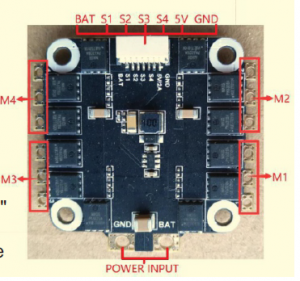
BAT: power positive electrode;GND: power negative electrode; 5V:5V regulated power supply output interface,maximum current 2A; S1-4: throttle signal input interface,S1 corresponds to M1.S2 corresponds to M2, S3 corresponds to M3, S4 corresponds to M4.Number electric adjustment;
POWER INPUT: power line pads, “GND”corresponding power supply.The line negative pole, “BAT” corresponds to the positive pole of the power supply line.4.0 Flight controller
 4.0 Flight controller
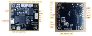
Product characteristics:The STM32 F405 master chip can run higher PID cycle time and gyroscope.Integrating accelerometers and gyroscopes using an ICM20602 chip with SPI bus (the highest operating frequency of the gyroscope can be set to32KHz);Flight control board OSD chip, supporting DMA mode (using F4 MCU to control OSD), can useBeta Flight tuning softwarePart adjustment parameters; Supporting BetaFlight firmware, you can use BetaFlight tuning software to easily adjust various parameters, more suitable for FPV flyingRow and competition;Support various types of receivers (such as: SBUS, SUMH, SUMD, SPEKTRUM1024/2048, XBUS, PPM, etc.)Type of receiver;With LED programmable signal output port, support programmable LED lamp strip, can adjust lamp strip color and flash mode through flight control;Has a voltagemonitoring port (BAT) and a current monitoring port (CRT) to monitor battery voltage and current (requiring additional electricity) Flow meter);It has a buzzer output port and supports an external alarm buzzer for voice warning or flight status notification.It has Micro USB interface to facilitate users to connect computers.
Interface definition chart:
5.0 Camera
Model:Turbo EOS1Image Sensor:1/3″ CMOS SensorHorizontal Resolution:1200 TVLTV System:NTSC / PAL optionIMAGE:4:3Synchronization:InternalElectronic Shutter:PAL: 1/50~100,000; NTSC: 1/60~100,000S/N Ratio:>52dB (AGC OFF)Video Output:CVBSLens:2.1mmMin. Illumination:Auto Gain Control:YESBLC:YESWDR:Global WDRDNR:2 DNRDimensions:14mm*14mm*16mmWide Power Input:DC 3.3-6VWork Temperature:-20℃~ + 60℃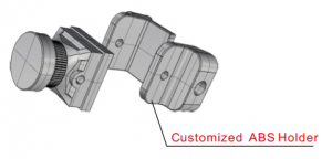
6.0 Switchable VTX
Output power & transmission distance: ≥,≥, ≥Transmitting power: 0mW/25mW/200mW/600mWFull video format: NTSC /PALInput voltage & power dissipation: 7V~24V, +12V/Size: 20*30*9mmWeight: ≤7g(except antenna)With output power self-check function.Nixie tube SCAN: frequency point (1-8), frequency band (A-E),power (1-3, 0=0mw, 1=25mw, 2=200mw, 3=600mw)-7-TYRO109 QUICK START GUIDEFrequency control method:Button frequency control (1-8): press the button for 2 secondsto enter the frequency setting, and press the button to changethe frequency CH1-8.Change the frequency band (A-E), set thefrequency, press the button for 2 seconds, then press the buttonto change the frequency group FR (A-E).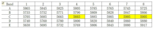
6.0 Switchable VTX
Points for attention:The antenna is installed at the output terminal before power up, so as not to damage internal components.Note that the input voltage is within the specified range and is positive or negative, so as not to damage internal components.If the antenna is replaced, choose a standing wave and a good gain antenna to obtain a longer transmission distance.Attention should be paid to electrostatic protection during transportation and installation.
7.0 Pagoda Antenna
Gain: 5dBiMax. Power: 50w Connector: RP-SMA Color: Black Weight: 8.6gLength: 78±3mm Max. Dia.: 22.4±1mm Min. Dia.: 11.8±1mmFrequency: 5.8G Impedance: 50Ω VSWR: <1.5:1Polarization: Circular Polarized Radiation: Omni
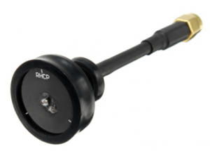
Features :Omni-directional, no dead corner High gain, more stable. Less flash, stonger siginal
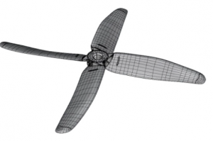
8.0 Propeller
Material: PC Mounting hole: 5mm Center thickness: 8mm Color: Green & Yellow &Red and Transparent White Color :Green & Yellow & Red and Transparent White Quantity: 2 CW + 2 CCW ( One Pair in each color)
9.0 Screws
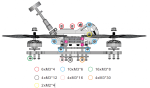
- M3*5mm ABS Round Isolation Column
- M3*3.5mm Rubber Shock Absorber
- M3*3.5mm Rubber Shock Absorber
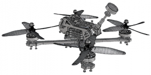
10.Exploded view
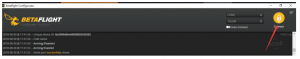
11.Adjusting parameter
- Click connect connection
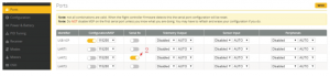
- Click the RX interface under UART2 under the ports option, as shown in the figure.
- Click CONFIGURATIN to change to dshot600
- Click CONFIGURATIN; change to SBUs
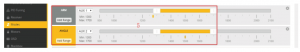
- Click modes, add arm and angle, drag the slider between 1300 and 1700, and set arm to AUX1 and angle to aux211.Adjusting parameter
- Push the slider to test the positive and negative rotation of the motor, such as error,
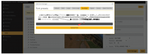
- Click font manager, select betaflight, click upload font
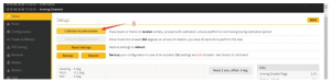
- Click setup, calibrate accelerometer


 11.Adjusting parameter
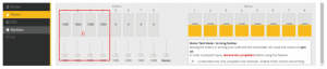
Read More About This Manual & Download PDF:
Eachine TYR0109 Racing Drone Quick Start Guide – Eachine TYR0109 Racing Drone Quick Start Guide –
[xyz-ips snippet=”download-snippet”]