
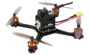
Eachine TYR069 Racing Drone Quick Start Guide
Package Include
- 1x integrated frame with 2.0mm plate thickness and 3D printing camera Mounting base
- 4X 1104 8600 kV (orange) motors
- 1X tyro69 20A 4 in1 ESC 1X tyro69 flight controller (main control chip: f411)
- 1X Caddx beetle V2 camera AIO FPV Transmitter
- 20X Paddle Blade
1.1 Frame kit
Axle Base: 105mmArm thickness: 2mmSupporting maximum wheelbase: 2.5 inchesSpacing of mounting holes for supporting motors: 9mmMaterial: 3K Carbon Fiber and TPU 3D Printing
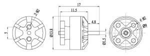
2.1 Motor
Model: 1104/8600 kVGroove Series: 9N/12PStator diameter: 11mmStator Height: 4mmAxis Diameter: 1.5mmWeight: 4.3GSupport supply voltage: 2-3sMaximum power: 144WInstallation hole: M2Installation hole spacing: 9mm
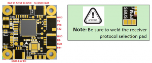
 3.1 ESC
 3.1 ESC
Continuous current: 20A Peak current: 25A (10s) BEC output: none Input voltage: 2-6 sMain Control Chip: EFM8BB21F16G Firmware upgrade: support dshot600/blheli_S/Oneshot125 MOS: 3*3
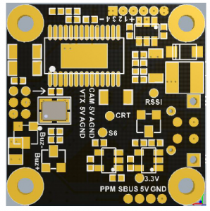
4.1 Flight Controller
 4.1 Flight Controller
Main control chip: stm32f411IMU: MPU 6000 6 axis sensor On-board integrated OSD BEC:5V2ADSMx/IBUS/sbus/UAR Sharing: UART1-RXInstallation Size: 20*20Weight: 24gSupport firmware: betaflight/cleanflight/inav
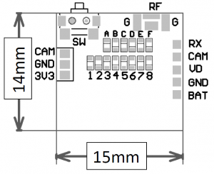
5.1 Camera image transmission
Output power: 25 MWSupport frequency: 48ch Support TBS Smart AudioSupport voltage: 2.9v-5.5vGraphic size: 15mm X14mmImage Sensor: 1/3 “CMOS Sensor”Horizontal Resolution: 1200 TVLTV System: PALIMAGE: 4:3Lens: 2.1mmDimensions: 14mm*14mm*16mmWeight: 4.1G (Camera + VTX) Picture from Miniature Antenna with Welded Copper Tube
6.1 Two-bladed propeller
Material: Imported PCInstallation aperture: 1.5MMWeight: 0.8g/pairQuantity: 10 pairsColor: translucent black/Black/Red/random
7.1 Recommended power supply
Recommended voltage: 3SRecommended capacity: 350-450 Mah
8.1 Adjusting parameter
- Configuration of UART port parametersEnter the Ports item, select the UART port (UART6 in this case), and then select the TBS Smart Audio item (Figure 1) in the Peripheral column to complete the configuration of the flight control image serial port. If the connection between the image transmission and the selected flight control UART port remains unchanged, this step only needs to be operated once. Figure 1
- Frequency grouping and channel number configuration1 Enter OSD parameter menuWhen VTX1 image transmission, corresponding image transmission receiver display screen and flight control are powered on, theinformation shown in Figure 2 will appear on the receiving screen. Figure 2Figure 2 Electrical display informationAt this time, according to the screen prompt operation THR MID (throttle center), YAW LEFT (YAW rocker to the left), PITCH UP (PITCHrocker to the top) into the OSD parameter adjustment menu (Figure 3). Figure 3Figure 3 OSD parameter menu2 Start grouping and channel configuration Under the OSD MAIN menu, the PITCH rocker can move the cursor arrow up and down to select the menu item, select the FEATURES item, then select the ROLL rocker to the right, and enter the lowerconfiguration menu (Fig. 4). Figure 4Figure 5 FEATURES MenuIn the menu of Figure 4, select the desired frequency grouping BAND and channel CHAN by swinging the ROLL rocker left and right.Note: Because VTX1 supports 48 channels, users can select any of the 48 channels by pressing keys. But at present, Betaflight’s OSD parametric function only supports 40 channels, so users can only configure 40 channels on the OSD screen. If the user chooses one of the eight channels that OSD parameters do not support and enters OSD parameters, the system will automatically change the user’s original channel to A1 channel on our frequency table (5865 Mhz), that is, the user can configure only 40channels with OSD parameters. After configuring the grouping and channel, you need to enter the SET item and select YSE to take effect (Figure 6). Figure 5Figure 6 Grouping and channel configuration validation 3 Output power configuration As in the previous section, the POWER item can be entered byremote control selection, and the required transmission power can be selected (Fig. 7). VTX1 currently supports only 25 mW power options,while the POWER menu with OSD parameters has four options: 25 mW, 200 mW, 500 mW and 800 mW. Therefore, users need to pay attentionto the choice of 200 mW, 500 mW, 800 mW options will be VTX1 set to 25 mW transmission power. Note: Unlike configuring BAND and CHAN, POWER settings do not need to enter the SET entry confirmation, and take effect immediately. Figure 64 Channel number indication The LED lamp displays the set grouping and channel, and the corresponding working frequency is shown in the table below.Note: Group F channel in italic part is not supported in BetaflightOSD configuration.
 Figure 1
 Figure 2Figure 2 Electrical display informationAt this time, according to the screen prompt operation THR MID (throttle center), YAW LEFT (YAW rocker to the left), PITCH UP (PITCHrocker to the top) into the OSD parameter adjustment menu (Figure 3).
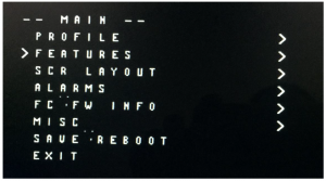 Figure 3Figure 3 OSD parameter menu2 Start grouping and channel configuration Under the OSD MAIN menu, the PITCH rocker can move the cursor arrow up and down to select the menu item, select the FEATURES item, then select the ROLL rocker to the right, and enter the lowerconfiguration menu (Fig. 4).
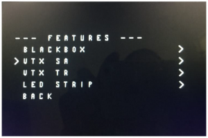 Figure 4Figure 5 FEATURES MenuIn the menu of Figure 4, select the desired frequency grouping BAND and channel CHAN by swinging the ROLL rocker left and right.Note: Because VTX1 supports 48 channels, users can select any of the 48 channels by pressing keys. But at present, Betaflight’s OSD parametric function only supports 40 channels, so users can only configure 40 channels on the OSD screen. If the user chooses one of the eight channels that OSD parameters do not support and enters OSD parameters, the system will automatically change the user’s original channel to A1 channel on our frequency table (5865 Mhz), that is, the user can configure only 40channels with OSD parameters. After configuring the grouping and channel, you need to enter the SET item and select YSE to take effect (Figure 6).
 Figure 5Figure 6 Grouping and channel configuration validation 3 Output power configuration As in the previous section, the POWER item can be entered byremote control selection, and the required transmission power can be selected (Fig. 7). VTX1 currently supports only 25 mW power options,while the POWER menu with OSD parameters has four options: 25 mW, 200 mW, 500 mW and 800 mW. Therefore, users need to pay attentionto the choice of 200 mW, 500 mW, 800 mW options will be VTX1 set to 25 mW transmission power. Note: Unlike configuring BAND and CHAN, POWER settings do not need to enter the SET entry confirmation, and take effect immediately.
 Figure 64 Channel number indication The LED lamp displays the set grouping and channel, and the corresponding working frequency is shown in the table below.
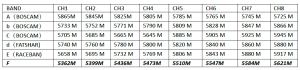 Note: Group F channel in italic part is not supported in BetaflightOSD configuration.
Read More About This Manual & Download PDF:
Eachine TYR069 Racing Drone Quick Start Guide – Eachine TYR069 Racing Drone Quick Start Guide –
[xyz-ips snippet=”download-snippet”]