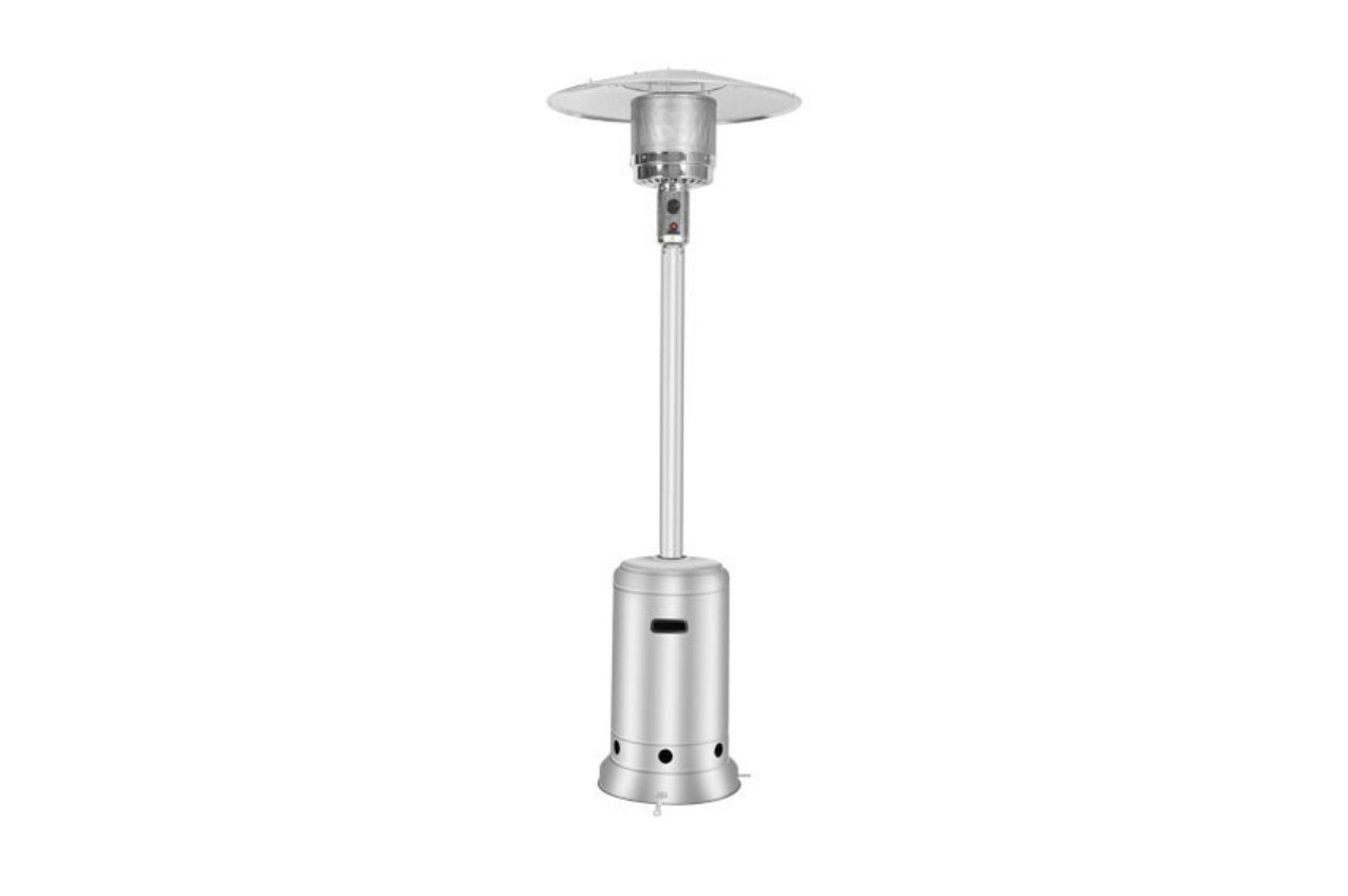
EASTERN Mushroom Heater 2890 Instruction Manual
![]() WARNING
WARNING
- Read the instruction before installation and use.
- Keep the instructions for future references.
- For use outdoors and in well ventilated areas.
- A well ventilatedarea must have a minimum of 25% of the surface area open.
- The surface area is the sum of the walls surface.
- Do not obstruct the ventilation holes of the cylinder housing.
- Do not move the appliance when in operation.
- Shut off the valve at the gas cylinder or the regulator before moving the appliance.
- This appliance must be installed and the gas cylinder stored in accordance with the regulation in force.
- The tubing or the flexibile hose must be changed within theprescribed intervals.
- Use only the type of gas and the type of cylinder specified by themanufacturer.
- In case of violent wind particular attention must be taken against tilting of the appliance.
CAUTION
PLEASE READ CAREFULLY THE FOLLOWING SAFETY GUIDELINES BEFORE OPERATION
- .Installation and repair should be done by a qualified service person.
- Improper installation, adjustment, alteration can cause personal injury or property damage.
- Do not attempt to alter the unit in any manner.
- Never replace or substitute the regulator with any regulator other than the factory- suggested replacement.
- Do not store or use gasoline or other flammable vapors or liquids into the heater unit.
- The whole gas system, hose regulator, pilot or burner should be inspected for leaks or damages before use.
- All leak tests should be done with a soap solution. Never use an open flame to check for leaks.
- Do not use the heater until all connections have been leak tested.
- Turn off immediately the gas valve if smell of gas is detected.
- Do not transport heater while it’s operating.
- Do not move the heater after it has been turned off until the temperature has cooled down.
- Keep the ventilation opening of the cylinder enclosure free and clear of debris.
- Do not paint radiant screen, control panel or top canopy reflector.
- Control compartment, burner and circulation air passageways of the heater must be kept clean.
- Frequent cleaning may be required asnecessary.
- The LP tank should be turned off when the heater is not in use.
- Check the heater immediately if any of the following exists:
- The heater does not reach temperature.
- The burner makes popping noise during use (a slight noise is normal when the burner is extinguished).
- Smell of gas in conjunction with extreme yellow tipping of the burner flames.
- The LP regulator/hose assembly must be located out of pathways where people may trip over it or in area where the hose will not subject to accidental damage.
- Any guard or other protective device removed for servicing the heater must be replaced before operating the heater.
- Change the gas cylinder in a well ventilated area ,away from any inflammation source.
- Check that the regulator seal is fitted and that it is in good condition.
- Do not obstruct the ventilation holes of cylinder housing.
- Adults and children should stay form high temperature surface to avoid burns or clothing ignition.
- Children should be carefully supervised when they are in the area of the heater.
- Clothing or other flammable materials should not be hung on the heater or placed on or near the heater.
- LP Characteristics – Flammable, explosive, heavier than air-settles in low areas.
- In its natural state, propane has no odor. For your safety, an odorant is added that smells like rotten cabbage.
- Contact with liquid LP can cause freeze burns to skin.
- This heater is shipped from the factory for LP gas use only.
- Use only EEC approved ”20lb.” LP gas cylinders (same as commonly used on gas grills) with safety valves.These valves can be quickly identified by their external and internal threads.
- Never use a cylinder with a damaged body, valve, collar or foot ring.
- When heater is not in use, turn Control ValveOFF.
- Always perform a leak test on gas connections whenever a cylinder is connected (see Page 4). Never use a flame to test for leaks. Do not smoke while performing a leak test.Note: Flame screen is quick-ware part.
HEATER STAND AND LOCATION
- The heater is primarily for outdoor use only. Always ensure that adequate fresh air ventilation is provided.
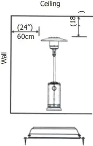
- Always maintain proper clearance to combustible materials, i.e. top 45cm(18”) and sides 60cm (24”) minimum.
- Heater must be placed on level firm ground.
- Never operate heater in an explosive atmosphere like areas where gasoline or other flammable liquids or vapors are stored.
- To protect heater from strong wind, anchor the base securely to the ground with screws.
 Fortification of base to the ground
 Fortification of base to the ground
GAS REQUIREMENTS
- Use propane or butane gas only .
- Maximum inlet pressure of propane regulator must not exceed 100 PSI.
- A minimum supply pressure of 28 mbar (11.0” W.C.) is required for the purpose of input adjustment for propane gas.
- The pressure regulator and hose assembly to be used must conform to local standard codes.
- The installation must conform to local codes, or in the absence of codes, with standard codes.
- The installation must conform to local codes, or in the absence of codes, with the standard for storage and handling of liquid petroleumgases.
- A dented, rusted or damaged propane tank may be hazardous and should be checked by your tank supplier.Never use a propane tank with a damaged valve connection.
- The propane tank must be arranged to provide for vapor withdrawal from the operating cylinder.
- Never connect an unregulated propane tank to the heater.
LEAKAGE TEST
Gas connections on the heater are leak tested at the factory prior to shipment. A complete gas tightness check must be performed at the installation site due to possible mishandling in shipment or excessive pressure being applied to the heater.
- The heater must be checked with a full cylinder.
- Make sure the safety control valve is in the OFF position.
- Make a soap solution of one part liquid detergent and one part water.The soap solution can be applied with a spray bottle, brush or rag.
- Soap bubbles will appear in case of a leak.
- Turn the gas supply ON.
- In case of a leak, turn off the gas supply.Tighten any leaking fittings, then turn the gas supply on and recheck.Contact your dealer for assistance if bubbles continue to appear.
- Never leak test while smoking.
FUEL GAS ODOR
LP gas and natural gas have manmade odorants added specifically for detection of fuel gas leaks.If a gas leak occurs you should be able to smell the fuel gas. Since Propane (LP)is heavier than air you should smell for the gas odor low to the floor. ANY GAS ODOR IS YOUR SIGNAL TO GO INTO
IMMEDIATE ACTION!
- Do not take any action that could ignite the fuel gas. Do not operate any electrical switches.Do not pull any power supply or extension cords. Do not light matches or any other source of flame. Do not use your telephone.
- Get everyone out of the building and away from the area immediately.
- Close all propane (LP) gas tank or cylinder fuel supply valves,or the main fuel supply valve located at the meter if you use naturalgas.
- Propane (LP) gas is heavier than air and may settle in low areas. When you have reason to suspect a propane leak, keep out of all low areas.
- Use your neighbor’s phone and call your fuel gas supplier and your fire department. Do not reenter the buiding or area.
- Stay out of the building and away from the area until declared safe by the firefighters and your fuel gas supplier.
- FINALLY, let the fuel gas service person and the firefighters check for escaped gas. Have them air out the building and area before you return. Properly trained service people must repair any leaks, check for further leakages, and then relight the appliance for you.
OPERATION AND STORAGE
TO TURN ON THE HEATER
- Turn on the valve on the gas supply cylinder completely.
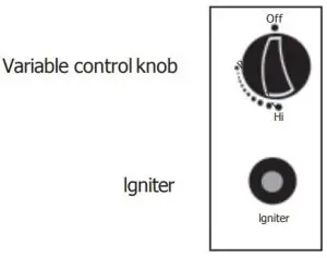
- Press and turn the variable control knob to PILOT position (counter-clockwise 90º)
- Press down the variable control knob and hold for 30 seconds. While holding down the variable control knob after the pilot flame lights.Note:
- If a new tank has just been connected, please allows at least one minute for the air in the gas pipeline to purge out through the pilot hole.
- When lighting the pilot flame make sure that the variable control knob is continuously pressed down while pressing the igniter button. Variable control knob can be released after the pilot flame lights.
- Pilot flame can be watched and checked from the small round window with sliding lid located at the bottom of the flame screen (to the left or right side of the controller).
- If the pilot flame does not light or it goes out,REPEAT STEP 3.
- After the pilot flame lights, turn the variable control knob to minimum position and leave it there for 5 minutes or more before turning the knob to desired temperature position.
TO TURN OFF THE HEATER
- Turn the variable control knob to pilotposition.
- Press and turn the variable control knob to OFF position.
- Turn off the valve on the gas supply cylinder completely.
Storage
- Always close the gas valve of the gas cylinder after use or in case of a disturbance.
- Remove the pressure controller and the hose.
- Check the tightness of the gas valve and for damage. If you suspect a damage, have it changed by your gas dealer.
- Never store liquid gas cylinder in a sub-terrain, or at places without adequate air ventilation.
Cleaning And Care
- Wipe off powder coated surfaces with soft, moist rag. For lacquer surface, use suitable cleaners. Do not clean heater with cleaners that are combustible or corrosive.
- Remove debris from the burner to keep it clean and safe for use.
PARTS AND SPECIFICATIONS
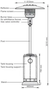
Construction and characteristics:
- Transportable terrace/garden heater with tank housing
- Casing in steel with powder-coating or stainless steel
- Soluble gas connections are equipped with metal clamp
- Stainless steel flamescreen
- Heat emission from reflector
Specifications
- For outdoor use only
- Uses propane or butane gas only
- Max. wattage: 12000 watts
- Min. wattage: 5000 watts
- Consumption: 450 g/hr – 870 g/hr
- Weight: Stainless steel model G.W. 20 kgs
- Powder coating model G.W. 22 kgs
- Height: 2210 mm including stand With CE certificate
Table of openings
| Gas Pressure mmH 2 O | Main Opening | Opening of Pilot Burner |
| 280/300 | 1.90mm | 0.18mm |
| 500 | 1.80mm | 0.18mm |
ASSEMBLY PARTS & PROCEDURES
Tools needed:
- Open end wrench 10 & 13 mmAdjustable opening wrench (2) 8’’ long
- Slip joint pliers 9” long
- Philips screwdriver w/ medium blade
- Teflon plumbing tape for joints
- Spray bottle of soap solution for leakage test
Parts supplied:
- Stand with LPG tank housing
- Assembly post with 3 pcs post brackets
- 10 mm x 86 cm (L) galvanized steel pipe
- Reflector 810 mm with 6 pcs washers Ø8 mm and 3 pcs castles nuts
- 3 pcs 60mm(L) pins for reflector support.
- 4 pcs bolts M6 x 10 mm for post and post and burner
- 6 pcs bolts & nuts M6 x 35 mm for post and post brackets
- 3 pcs bolts M8 x 16 mm for post brackets and stand
- 3 pcs ground fixer
- 6 pcs M6 x 10 mm ground fixer bolts & nuts
Assembly Procedures
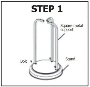
STEP 1
- Put the three pcs post brackets on each position on the base as shown in the picture.
- Use 3 pcs M8 x 16 mm bolts to join the post brackets and stand.
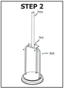
STEP 2
- Put the post onto the top of 3 pcs post brackets.
- Use 6 pcs M6 x 35 mm bolts and nuts to connect the post to the 3pcs post brackets. Tighten the bolts and nuts.
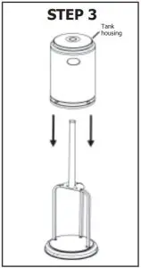
STEP 3
- Put the tank housing through the post.
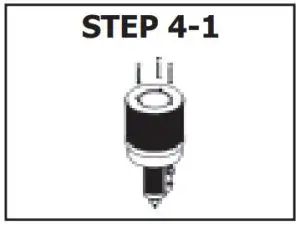
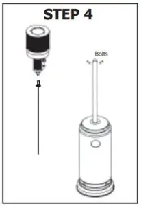
STEP 4
- Fit the gas steel pipe nut into the burner gas inlet connector.
- Secure the reflector support bolts on the flame screen cap with 3 pcs 60 mm length pins & 3 pcs Ø8 mm washers.
- Connect the pins & washers to the flame screen.
- Tighten the pins.
- Tighten the gas steel pipe nut and gas inlet thread.
- Put the burner with steel pipe onto the post.
- Fix the burner base to the post by 4 pcs M6 x 10 mm bolts.
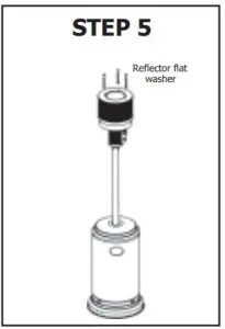
STEP 5
- Check whether the connection of vertical post and burner are assembled asinstruction, and all bolts and nuts are tightened.
- Put the flat washer onto the top of each burner/reflector support bolts(M8 thread).
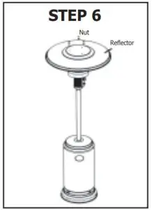
STEP 6
- Put the reflector on top of the burner and passing through 3 pcsburner/reflector support bolts.
- Fit washers into each support bolt and tighten each by M8 castle nut.
 report this ad
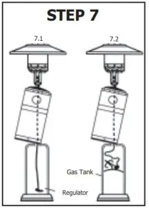
STEP 7
- Bring up the tank housing and rest it on the post plate.
- Fit the gas regulator rubber hose with the end thread of inlet gas steel pipeand tighten the nut.
- Connect the regulator with the LPG gas tank in counter-clockwise directionand tighten it by adjustablewrench.
- Put the LPG gas tank into stand.
PROBLEMS CHECK LIST
| PROBLEMS | PROBABLE CAUSES | SOLUTIONS |
| Pilot will not light | Gas valve may be OFF | Turn the gas valve ON |
| Tank fuel empty | Refill LPG tank | |
| Opening blocked | Clean or replace opening | |
| Air in supply system | Purge air from lines | |
| Loose connection | Check all fittings | |
| Pilot will not stay on | Debris around pilot | Clean dirty area |
| Loose connections | Tighten connections | |
| Thermocouple bad | Replace thermocouple | |
| Gas leak in line | Check connections | |
| Lack of fuel pressure | Tank near empty. Refill LPG tank | |
| Burner will not light | Pressure is low | Tank near empty. Refill LPG tank. |
| Opening blocked | Remove and clean | |
| Control not on | Turn valve to ON | |
| Thermocouple bad | Replace thermocouple | |
| Pilot light assembly bent | Place pilot properly | |
| Not in correct location | Position properly and retry |
References
[xyz-ips snippet=”download-snippet”]