
EchoTherm DIGITAL, ELECTRONIC CHILLING/HEATING DRY BATH
 MODEL IC50
INTRODUCTION
Congratulations on your purchase of an EchoTherm Digital Electronic Chilling/Heating Dry Bath Model IC50. Please read the instructions carefully to insure that you receive the maximum benefit from it. Also, be sure to go to our web site and register your unit for warranty coverage. When users in the USA and Canada do they will receive a Torrey Pines Scientific, Inc. T-Shirt free.
WARRANTY
Torrey Pines Scientific warrants this product to be free from defects in material and workmanship for a period of one year from the date of purchase. If repair or adjustment is necessary and has not been the result of abuse or misuse within the one year period, please return—freight prepaid—and correction of the defect will be made without charge. Out of warranty products will be repaired on a charge basis.
RETURN OF ITEMS
Authorization must be obtained from our Customer Service Department before returning items for any reason. When applying for authorization, please include data regarding the reason the items are to be returned. For your protection, items must be carefully packaged to prevent damage in shipment and insured against possible damage or loss. Torrey Pines Scientific will not be responsible for damage resulting from careless or insufficient packing. A 15% restocking charge will be made on all unauthorized returns.
Note: Torrey Pines Scientific reserves the right to make improvements in design, construction, and appearance without notice.
LABELS
There are various labels on the body of this unit. Listed below are the labels and their meanings.This symbol means AATTENTION. The INSTRUCTION MANUAL IS TO BE CONSULTED FOR FURTHER This symbol means AWARNING, HOT
CAUTIONS
CHILLER/HEATER PLATE SURFACE
The IC50 is capable of chilling and heating the plate surface from -10.0ºC to 110.0ºC without the sample block. The upper temperature of 110.0ºC (230ºF) is hot enough to burn the skin if touched. Use extreme caution at all times. Never leave your unit accessible to others when it is hot. Never touch the plate surface unless you are sure it is cool. Note that there is a red LED on the front panel marked HOT. This will illuminate when the heater surface goes above 50.0°C (122°F).
ELECTRICAL
The IC50 cooling/heating module runs using 12 volts DC at 8.3 amps. These instruments are supplied with a universal power supply that can take inputs from 100 to 260 volts AC, 50/60 Hz. The units are supplied with an AC input cord for the power supply. Be certain to use a line cord with the same rating and of the same type as the one supplied by the manufacturer. Use the normal care and precaution one would use with any electrical appliance.
GENERAL DESCRIPTION
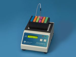
The IC50 is Peltier driven for chilling & heating. It comes with a universal power supply and the chilling/heating module. It has only one moving part, the DC fan that cools the unit. Everything else is solid state and should last years for without problem. All functions of the unit are accessible from the front panel via the membrane switch and accompanying digital display.
HEATER/CHILLER PLATE
The surface is a very flat aluminum plate designed for good contact with any flat surfaced item placed on it. The plate size of the IC50 is 2.875″ (73 mm) x 4.375″ (111 mm). It will chill and heat quickly without a load on it. The temperature of the plate is sensed by a platinum RTD mounted under the plate. When using the plate sensor to control the unit the computer in the unit compares the plate temperature with the target temperature and instructs the Peltier module to heat or chill the plate as required. Direct control of the sample or block temperature can be attained by using the temperature probe provided with the unit and placing it into the sample or block.
TIMER
The IC50 has a count down timer reading in hours, minutes, and seconds. It can be set to a maximum of 99 hours. The timer will be displayed at the same time as the SET POINT and TEMP. It has a user settable AUTO-OFF as well. This works to turn the chiller/heater target temperature off when the timer counts to zero.
Torrey Pines Scientific, Inc.
ALARM
The unit has an audible alarm that sounds for one minute when the timer counts down to zero. Touching the UP ARROW will turn the alarm off during this first minute. However, if the alarm sounds for the entire minute, it will shut-off the sound automatically. When the alarm first sounds, the timer will start to count up. This lets the user know how much time has passed since the timer first sounded.
FRONT AND REAR PANEL CONTROLS
FRONT PANEL
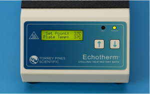
The IC50 front panel shown above has a tactile touch membrane keyboard with audiblefeedback. The keyboard is used to set all operating parameters. The display is a two-line alphanumeric LCD with backlighting. When the unit is turned on the display will light and show the SET POINT and PLATE. Plate temperature will be displaying the actual temperature of the plate surface. When the probe is plugged in the display temperature will be the temperature the probe is sensing. There are two LED=s on the front panel. One a power-on indicator and the other is the plate surface hot indicator.
REAR PANEL
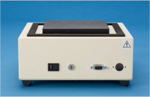
The rear panel shown has the on/off power switch at the left, the 12 volt dc power input jack in the middle, the RS232 I/O port next to that, and the probe jack on the right.
SET UP PARAMETERS
SET UP PARAMETERS
- Ambient operating room temperature range is from 5ºC to 40ºC.
- Maximum altitude of operation should not exceed 2000 meters.
- Maximum ambient operating relative humidity should not exceed 80% at 31ºC decreasing linearly to 50% relative humidity at 40ºC.
SET UP INSTRUCTIONS
- Place the unit on a level, dry surface.
- Plug the power supply into the line cord provided and then into a properly grounded, 3-wire outlet of proper voltage.
- Plug the power supply cable into the rear of the chilling/heating module.
- If direct sample or sample block control is desired then plug the temperature probe into the jack on the rear panel and place the probe into the sample or block. Be certain not to leave the probe on the bench or the unit will try to heat or chill the room by running to maximum heat or cold.
- Place the sample block on the plate surface and place the sample probe into the sample or block if direct sample or sample block control is desired. If the probe is not used then the sensor in the heating/chilling plate will be used to control the temperature set.
- Turn the unit on by the switch on the rear of the chilling/heating module. The unit display will light and the power LED will illuminate. Set target temperature and timer, if wanted, according to the instructions that follow.Note: Do not use this equipment in any manner not specified by the manufacturer.
ENVIRONMENTAL INFORMATION
- This unit is for installation category II.
- This unit is rated pollution degree 2.
DISPLAY AND KEYBOARD DESCRIPTIONS
DISPLAY
The display is a two-row alphanumeric LCD with backlighting for easy viewing. It is used to set all the parameters of the units. When used with the keyboard, it can be made to set a temperature, to set a timer, and to calibrate the temperature against a local standard.
KEYBOARD
The keyboard consists of an UP ARROW and a DOWN ARROW. When the keys are touched, an audible beep will occur. The keys also have tactile feedback when they are depressed. Use of these arrows will be described next.
SETTING TEMPERATURE, TIMER
There are some general points to remember when using the IC50. Although the units can be set to -10.0ºC they can only go 30.0ºC below ambient room temperature at the plate surface without a sample block. As an example, if room temperature is 30°C, the unit will not cool below 0°C at the plate surface. The same is said for setting the maximum temperature of 110.0°. Low room temperatures will affect how high the unit can go. Also, sample blocks add mass depending upon their size, and they can keep the unit from heating or cooling to its limits of -10.0°C to 110.0°C. Some larger loads may not heat or cool as wanted, or, if they do, it will take longer than the unloaded plate. Covering or wrapping the sample blocks with something as simple as a paper towel will improve performance. We sell covers for some of the blocks as well. The part number for the cover for the aluminum blocks is 720-0009. These help improve performance.
SETTING CONTROL TEMPERATURE
The IC50 has the ability to control to the set point temperature based on inputs from either an embedded temperature sensor in the plate or from a plugged-in probe. The probe must be a specific design available only from Torrey Pines Scientific. If a probe is not plugged in, the IC50 will default to controlling temperature using the internal plate temperature sensor. The user has the option of specifying the method of control from three potential sources—the temperature sensor embedded in the plate (“Control Using: Plate”), a probe placed in the sample such as a liquid (“Control Using: Probe in Sample”), or by probe placed in the probe hole of a sample block (“Control Using: Probe in Block). See www.torreypinesscientific.com for information about sample blocks. See the menu map in Figure 1 for details on setting the selected temperature.
 Figure 1: Menu Map to Set the Control Temperature to Plate, Probe in Sample, or Probe in Block
SETTING TIMER
The timer is a count down timer that reads in hours, minutes, and seconds continuously. It can be set to 59 hours, 59 minutes and 59 seconds maximum. When the timer counts down to zero, it will sound an audible alarm for one minute. When the alarm starts to sound, the unit will then count up so that the user may see how long it has been since the alarm timed out. The audible alarm can be turned off after it has sounded by depressing the UP or DOWN ARROW.When the timer is set, the display will show the timer value in hours, minutes, and seconds on the bottom line of the display. The top line of the display will now show the SET POINT as SP and then the value as set and the display will show the PLATE TEMP as PL and the actual plate temperature. The other timer options under TIMER OPTIONS are AUTO-OFF, STOP TIMER and BEEP.
See Figure 2 and Figure 3 for more details on how to set, start, and stop the timer. Figure 4 shows how to select from the various Timer Options.
 Figure 2: Menu Map to Set and Start the Timer
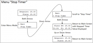 Figure 3: Menu Map to Stop the Running Timer
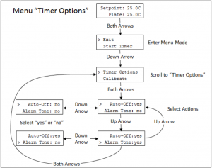 Figure 4: Menu Map to Select Timer Options
SETTING THE UNIT TO “IDLE MODE”
Setting the IC50 to “Idle Mode” will turn off power to the heater/chiller assembly and allow the sample to heat up or cool off depending on the ambient conditions. It is essentially turning the set point off, which is why the set point on the LCD indicates “off” when the unit is in Idle Mode. Setting Idle Mode is accomplished by entering the Menu mode, scrolling to “Set Idle Mode”, and pressing both arrow buttons. Clearing Idle Mode is the same as setting it but the Menu option will read “Clr Idle Mode” when the unit is in Idle Mode. Additionally, the Idle mode can also be cancelled by pressing either the Up or Down arrow buttons on the keypad. When Idle mode is cancelled, the set point for the unit will return to the value that it was when the unit entered Idle Mode. See Figure 4 and Figure 5 for details on setting and clearing Idle Mode.
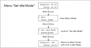 Figure 5: Menu Map to Set Idle Mode
 Figure 6: Menu Map to Clear Idle Mode
TEMPERATURE CALIBRATION
The temperature calibration built into the units is traceable to NIST. It is stable and will hold without drifting. However, our standards for temperature measurement may not be the same as the users. Therefore, these units are designed to be calibrated in the field by the user. Follow the easy instructions below if calibration is wanted or needed.
Note: The calibration is two-point for optimum accuracy. Therefore, if calibration is changed, it is best to first clear the old calibration in memory. The unit is calibrated at the factory at 5’C and 70’C.
To calibrate the units follow the instructions below. NOTE: THE PLATE SURFACE AND BLOCK SURFACE MEASUREMENTS ARE DIFFICULT TEMPERATURE MEASUREMENT TO MAKE ACCURATELY. Check with the factory if help is needed. Also, calibration kits are available. The IC50-700 is the probe calibration kit, and the plate and probe calibration kit is IC50-800. The IC50-800 includes the probe calibration kit and a temperature meter and surface temperature probe like the ones we use here to calibrate the units in the factory. The probe circuit is calibrated using precision platinum resistors that equate to the temperature values of 5.0°C and 70.0°C. These resistors are mounted into packages that plug into the rear of the unit in place of the probe. Follow the instructions below to calibrate the plate surface, block surface or probe.
 Figure 7: Menu Map to Calibrate Plate and Probe Temperatures
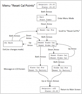 Figure 8: Menu Map to Reset Calibration Points back to Factory Set Values
RS232 INTERFACE
The RS232 is available through the 9-pin D-subminiature connector on the rear of the unit. Pins 2, 3 and 5 on the connector are used. It operates at 9600 baud, 1 stop bit, no parity. No handshake hardware or software is necessary. All communications settings and queries are done using ASCII characters with carriage return as the terminating character. See instructions at the end of this manual for the Serial Command Set.
Note: To comply with CE and to avoid possible EMI radiation from the RS232 cable, use a shielded cable.
CLEANING, MAINTENANCE, AND CONSUMABLE PARTS
CLEANING
These units are subject to splashes and spills during normal use. Also, condensation may occur when heating after chilling. Be sure to wipe up all spills and condensation with a soft cloth or paper towel as they occur. If a cleaning solution is necessary, use a mild soap or detergent solution and a soft cloth. Do not use solvents. They could damage the paint or display window on the unit.
Caution: Do not attempt to clean the plate surface when hot. Burns might occur.
MAINTENANCE
There is no ongoing maintenance program needed with these units other than the normal care and cleaning as instructed above, and a simple inspection done whenever the unit is to be used. This simple inspection should include:
- Checking that the AC cord and the DC cable to and from the power supply module are not frayed or burned.
- Checking that the unit is not dirty to a point where proper performance is impaired. This is especially important relative to the membrane switch and LCD window.
- Being certain to store the unit properly, when not in use, in an area that will not have items placed on top of the unit, and covering the unit in a way that will keep dirt and other foreign bodies out of the unit.
Note: Outside electrical interference such as lightning might on occasion cause the unit to lock up or change target temperature without being instructed to do so. The unit should be reset if this happens. To reset the unit turn it off from the rear panel switch and turn it on again while depressing the DOWN Arrow.
SPARE PARTS AND CONSUMABLES
There are very few spare or consumable parts. A simple list is below.
Part Number: Description730-0001: Power Cord, US730-0002: Power Cord, Germany (European)730-0003: Power Cord, UK730-0004: Power Cord, Italy730-0005: Power Cord, Australia/China
ADDITIONAL SYMBOLS
RESETTING THE UNIT TO ALL ORIGINAL FACTORY SETTINGS
These instructions should be used to reset the unit to all original factory settings. This includes the original factory calibrations. If for some reason the unit is acting strangely, or if you feel the calibrations have been reset incorrectly, following these steps will reset everything in the unit to original factory values.
Unit Rest Procedure:
- Turn unit power switch off.
- Press and hold the UP or DOWN arrow on the front panel while turning the power switch on.
- Continue to press the UP or DOWN arrow for approximately 10 seconds unit the display says “IC50 v1.0 Unit Rest”.
- Release the UP or DOWN arrow. The unit will then restart. At this point, all user menu settings and calibration points will be cleared and rest to default values.
- To restore the plate calibration values to the factory shipped values, press both UP and DOWN arrows together to get to the menu mode, scroll down to and select “Reset Cal Pts”, then select “Reset Plate Cal”. The unit will restore calibrations back to the factory values and display the message “Plate Cal Pts Reset to Factory”.
- To restore the probe calibration values to the factory values, press both the UP and DOWN arrows to get into the menu mode, scroll down to and select “Reset Cal Pts”, then select “Reset Probe Cal”. The unit will restore probe calibrations back to the factory values and display the message “Probe Cal Pts Reset to Factory”.
The unit can be rest using the RS232 commands. See the appropriate steps the in serial command set.
TORREY PINES SCIENTIFIC, INC.2713 Loker Ave. WestCarlsbad, CA 92010TELEPHONE: (760)-930-9400TOLL FREE: (866)-573-9104FAX: (760)-930-9480E-Mail: [email protected]Web site: www.torreypinesscientific.com
Echotherm Digital, Electronic Chilling/Heating Dry Bath Mode #IC50 Operating Manual – Echotherm Digital, Electronic Chilling/Heating Dry Bath Mode #IC50 Operating Manual –
[xyz-ips snippet=”download-snippet”]