Owner’s Manual12 Volt Battery BackupSump Pump System
Before you startSafety: Need safety Info1. Avoid Pressure Burns/Explosion2. Avoid Electric ShockMotor’s Electrical Settings: Set motor to the proper voltage, i.e. voltage supplied to pump – See electrical sectionNeed Help: Call 1-877-326-3561 for assistance; Do Not Return to Store
GENERAL SAFETY
IntroductionReasonable care and safe methods should be practiced. Check local codes and requirements before installation. This manual contains important information for the safe use of this product. Read this manual completely before using this product and refer to it often for continued safe product use.DO NOT THROW AWAY OR LOSE THIS MANUAL. Keep it in a safe place so that you may refer to it when needed.IMPORTANT SAFETY INSTRUCTIONSBefore proceeding further kindly go through the safety instructions carefully. Always disconnect the unit from the receptacle power source and battery before handling or making any adjustments to the system.Battery Backup Warning: WARNING Risk of electrical shock this unit has not been investigat-ed for use in outdoor areas.
WARNING Risk of electrical shock. Connect only to a properly grounded, three-pronged grounding-type receptacle. Under any circumstances, do not remove the grounding prong from the power cord.
WARNING Do not smoke, use sparkly electrical devices or open flame when working on this unit!
WARNING Do not install unit in locations classified as hazardous per N.E.C., ANSI/NFPA 70 – 1999.FAILURE TO HEED THE ABOVE CAUTIONS COULD RESULT IN INJURY OR DEATH.
WARNING The Eco-One system is designed to operate ONLY ONE PUMP, the one supplied with the unit. Using anything other than the pump supplied with the system will cause damage to the unit and void the warranty.General Precautions:Before using the inverter read all instructions and caution markings on the inverter, the batteries & all appropriate sections of this instruction manual.
WARNING Do not expose the inverter to any type of chemicals. The inverter is designed for interior use only.
WARNING Do not disassemble the inverter; take it to a qualified service center when service or repair is required.Opening by unqualified personnel can lead to electrical shock or fire hazards and void the warranty.To reduce risk of electric shock, disconnect all wiring before cleaning.
WARNINGAvoid exposing the inverter or batteries to any type of ex- plosive gases (in the vicinity, as batteries generate explosive gases during normal operation).
For parts or assistance, call ECO-FLO Customer Service at 1-877 326-3561Provide proper ventilation. The battery enclosures should be designed to prevent accumulation and concentration by hydrogen gas in “pockets” at the top of the compartment. Vent the battery compartment from the highest point. A sloped lid can also be used to direct the flow to the vent opening location. To reduce the risk of the battery explosion, follow all the instructions of the battery supplier or any equipment you intend to use in the vicinity of batteries. WARNING Use the correct insulated tools to make AC/DC wiring connections.
WARNING Do not install this inverter on or near flammable materials (plywood, chemicals, gas online etc.)Personal Precautions:
CAUTION Someone should be within the range of your voice to come to your aid when you work near batteries.
CAUTION Have plenty of fresh water and soap nearby in the event that battery acid contact skin, clothing or eyes.
CAUTION Wear complete eye and clothing protection.
CAUTION Avoid touching eyes while working near batteries. Wash your hands when done.
CAUTION If battery acid comes in contact with skin or clothing, wash immediately with soap and water.
KNOWING YOUR INVERTER
In its most basic form, an inverter transforms Direct Current (DC) to Alternating Current (AC). The battery pack acts as a reserve to ensure a continuous supply of power whenever mains supply from utility power is not available. The inverter is used to charge the batteries when normal utility power is available and converts the battery’s DC to AC voltage to run the pump when utility power is lost.
BATTERY SAFETYA battery can present a risk of severe burn and injury from a high short circuit current. The following precautions should be observed when working on batteries.
- Do not dispose of the battery in a fire. The battery may explode.
- Do not open or mutilate the battery. Released electrolyte is harmful to the skin and eyes. It may be toxic.
- The electrolyte is a dilute sulfuric acid that is harmful to the skin and eyes. It is electrically conductive and corrosive. The following procedures should be observed:a. If electrolyte contacts the skin, wash it off immediately.b. If electrolyte contacts the eyes, flush thoroughly and immediately with water. Seek medical attention.c. Spilled electrolyte should be washed down with a suitable acid-neutralizing agent. A common practice is to use a solution of approximately one pound (500 grams) bicarbonate of soda to approximately one gallon (4 liters) of water. The bicarbonate of soda solution is added until the evidence of reaction (foaming) has ceased. The resulting liquid should be flushed with water and the area dried.
- Do not reverse the battery connections, as it will blow the battery fuse. A power cord has been provided to connect the inverter to the incoming AC wall outlet.
BATTERY REQUIREMENTSYour unit operates on 12VDC battery power when in the power fail mode. A UL recognized deep cycle marine battery should be used. There are two principal types of batteries: starting and deep cycle. There are several different types of battery constitutions including liquid led acid, nickel-iron, nickel-cadmium, alkaline and maintenance-free. Batteries are sealed or vented.Starting Batteries Starting batteries are designed for high cranking power but not deep cycling. Do not use them with your inverter. They do not affect the inverter, but they will simply not last long in a deep cycle application. They use lot of thin plates to maximize the surface area of the battery. This allows a very high starting current but less run time when the battery is cycled.Deep Cycle Batteries Deep cycle batteries are best suited for use with the inverter. They are designed to have the majority of their capacity used before recharge.Available in many sizes and types, be sure to use at least an 80AH battery.BATTERIES NOT INCLUDED
CONTENTS
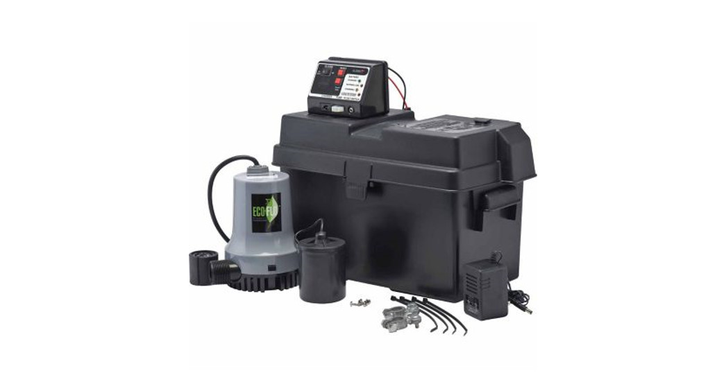
| 1 – 12 volt battery backup sump pump1 – Control/alarm panel1 – Float switch1 – 12 volt battery charger1 – Extra fuse2 – Battery terminal post clamps | 2 – Wire ties1 – Plastic battery case (Battery not included)1 – Dual pipe size (1-1/2” or 1-1/4”) PVC tee with a 1” threaded fitting for installing the pump4 – Mounting screws |
TOOLS & MATERIALS NEEDED
| TOOLS:Adjustable wrench or socket wrenchScrewdriverHack saw or PVC pipe cuttersFile or sandpaper for sanding cut pipeClean cloth for wiping water debris | MATERIALS:PVC cement and primerOne 12 Volt Group 24 Deep Cycle MarineBattery |
INSTALLATION
WARNING DISCONNECT ELECTRICAL POWER FROM PRIMARY SUMP PUMP
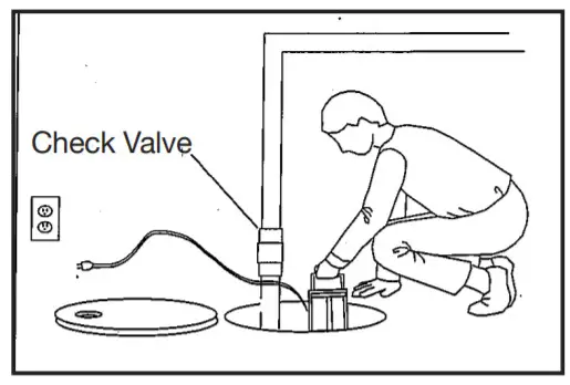
STEP 1:Disconnect check valve or coupling from the discharge pipe and primary sump pump. Then remove the primary sump pump and pipe assembly from the sump and place in a well-lit work area. Re-install the check valve at the sump discharge or base. Be sure the check valve is below the backup pump.
 STEP 2:Hold the automatic float switch up in the hold position. Mark that location on the discharge pipe. From that mark, measure up the pipe 2” and mark the pipe again. At the second mark, cut off a section of the discharge pipe as described below, to allow space for the supplied pump installation tee.If the discharge is 1-1/4” pipe, cut off 1-1/2” of pipe.If the discharge is 1-1/2” pipe, cut off 2” of pipe.
STEP 3:Thread the Battery Backup Sump Pump onto the dual-size pipe tee provided. Once the pump is threaded tight and set parallel to the discharge pipe, turn the pipe to the 2 o’clock position to prevent air from being trapped in the pump housing. Then cement the installation tee to the discharge pipe with PVC primer and PVC cement.
STEP 4:Replace primary sump pump and Battery Backup Pump assembly into the sump basin. The top of the Battery Backup Pump should be at least 4” below the top of the sump and at least 1” above the highest water level of the primary sump pump. Connect the remaining discharge pipes, check valve, and couplings.
STEP 5:Attach the automatic float switch to the discharge pipe so that the switch is tethered 1-1/4” from the discharge pipe. Use the supplied wire straps to mount the float switch cord to the discharge pipe.

STEP 6:Feed the pump and float switch cords through the sump pump vent or utility hole and cover the sump with the sump cover.
BATTERY & CONTROL/ALARM PANEL ASSEMBLY
STEP 1:Mount the Control/Alarm Panel to the battery case using the four mounting screws provided. The battery case has four mounting holes predrilled for easy installation of the control panel. For best results, use a Group 24, marine battery. Battery dimensions should not exceed: 9” high (including post) x 12” long x 6-1/2” wide.
STEP 2:Insert the marine battery into the battery case. Attach the RED and BLACK wires from the back of the control/alarm panel to each of the battery clamps provided. Then connect battery clamps to the battery. RED WIRE to the POSITIVE (+) terminal and the BLACK WIRE to the NEGATIVE (-) terminal.
STEP 3:Plugin the designated components to the control/ alarm panel, A battery backup pump, B the float switch, C and the 12-volt transformer.
STEP 4:Turn the alarm switch on the control/alarm panel to the OFF position and plug the 12-volt transformer in a GFCI outlet. If a GFCI outlet is unavailable, have an electrician install one for you. Once proper power is supplied, turn the alarm switch to the on position. Then plug the primary sump pump to its power source.
YOUR BATTERY BACKUP SUMP PUMP SYSTEM IS READY.
TESTING THE SYSTEM
STEP 1:Disconnect the power to the primary sump pump so the only pump available is the Battery Backup Sump Pump.STEP 2:With a garden hose or buckets of water fill the sump basin with water. At the designated level of water, the Battery Backup Sump Pump should activate and the ALARM and ALARM INDICATOR LIGHT should come on. This indicates the system is working.STEP 3:Press the RESET button on the control/alarm panel and reconnect power to the primary sump pump. The test is complete.NOTE: If the Battery Backup Sump Pump failed to activate, review the complete instructions.
NORMAL OPERATION
The Battery Backup Sump Pump is designated as an emergency backup pump in the event your primary sump pump fails or if there is a loss of power to your primary sump pump.
THE BATTERY BACKUP SUMP PUMP IS NOT INTENDED FOR USE AS A PRIMARY SUMP PUMP.
PRIMARY SUMP PUMP FAILURE
In the event your primary sump pump fails or loses power, the Battery Backup System will automatically activate when the float switch reaches the ON position. When it turns on, an alarm will sound and the alarm indicator will light. When the water in the sump basin recedes and the pump turns off, the alarm will continue to sound until you depress the ON/OFF switch to the on/off switch to the ON position and press the REST button.
BATTERY LOW
In the event 12-volt battery charge should drop lower than 11 volts, the alarm will sound and the BATTERY LOW indicator will light. Press the ON/OFF switch to OFF position, disconnect power to the 12-volt transformer from the GFCI outlet and disconnect the pump and float switch cords from the alarm/ control panel plugs. Have the battery checked, serviced or replaced if necessary. Once the 12-volt battery is serviced or replaced, reconnect all plugs, cables and power and follow the Test Procedures listed in this owner’s manual.
BATTERY CHARGING/CHARGED
When the battery is not at full charge capacity, the BATTERY CHARGING indicator will light. The battery charging is simply recharging the battery to its full charged capacity. Once the battery has reached full charging capacity (13 volts) the CHARGED indicator will light.
If neither the BATTERY CHARGING or CHARGED indicator lights are on, check all wire connections and plugs to ensure proper hook up.
LEADS REVERSED
If you connect the battery cable to the wrong battery terminal, the LEADS REVERSED indicator will light. Simply remove the battery cable and reconnect to the proper battery terminals. The RED WIRE is connected to the positive (+) terminal and the BLACK wire is connected to the negative (-) terminal.You must replace the 1 amp fuse with the extra fuse provided. Simply turn the fuse cover counter clockwise until the burnt fuse is exposed. Replace the fuse and thread the fuse cover, turning clockwise.
BATTERY MAINTENANCE
The 12-volt marine battery should be tested every four to six months. It is recommended to replace the battery every three to four years. Follow the battery manufacturers’ recommendations for proper battery maintenance and battery replacement.
WARRANTY
report this adRetain Original Purchase Receipt for Warranty EligibilityLimited Warranty
Manufacturer warrants to the original consumer purchaser (“Purchaser” or “You”) that its products are free from defects in material and workmanship for a period of twelve (12) months from the date of the original consumer purchase. If, within twelve (12) months from the original consumer purchase, any such product shall prove to be defective, it shall be repaired or replaced at the manufacturer’s option, subject to the terms and conditions set forth herein. Note that this limited warranty applies to manufacturing defects only and not to ordinary wear and tear. All mechanical devices need periodic parts and services to perform well. This limited warranty does not cover repair when normal use has exhausted the life of a part or the equipment.The original purchase receipt and product warranty information label are required to determine warranty eligibility. Eligibility is based on the purchase date or original product — not the date of replacement under warranty. The warranty is limited to repair or replacement of originally purchased product only, not replacement product (i.e. one warranty replacement allowed per purchase).Purchaser pays all removal, installation, labor, shipping, and incidental charges.Claims made under this warranty shall be made by returning the product to the retail outlet where it was purchased or to the factory immediately after the discovery or any alleged defect. The manufacturer will subsequently take corrective action as promptly as reasonably possible. No requests for service will be accepted if received more than 30 days after the warranty expires. Warranty is not transferable and does not apply to products used in commercial/rental applications.General Terms and Conditions; Limitations of RemediesYou must pay all labor and shipping charges necessary to replace the product covered by this warranty. This warranty does not apply to the following: (1) acts of God; (2) products which, in manufacturer’s sole judgment, have been subject to negligence, abuse, accident, misapplication, tampering, or alteration; (3) failures due to improper installation, operation, maintenance or storage; (4) atypical or unapproved application, use or service; (5) failures caused by corrosion, rust or other foreign materials in the system, or operation at pressures in excess of recommended maximums.
This warranty sets forth the manufacturer’s sole obligation and the purchaser’s exclusive remedy for defective products. THE MANUFACTURER SHALL NOT BE LIABLE FOR ANY CONSEQUENTIAL, INCIDENTAL, OR CONTINGENT DAMAGES WHATSOEVER. THE FOREGOING LIMITED WARRANTIES ARE EXCLUSIVE AND IN LIEU OF ALL OTHER EXPRESS AND IMPLIED WARRANTIES, INCLUDING BUT NOT LIMITED TO IMPLIED WARRANTIES OF MERCHANTABILITY AND FITNESS FOR A PARTICULAR PURPOSE. THE FOREGOING LIMITED WARRANTIES SHALL NOT EXTEND BEYOND THE DURATION PROVIDED HEREIN.
Some states do not allow the exclusion or limitation of incidental or consequential damages or limitations on how long an implied warranty lasts, so the above limitations or exclusions may not apply to You. This warranty gives You specific legal rights and You may also have other rights which vary from state to state.
1899 Cottage Street, Ashland, Ohio 44805Telephone: 1-877-326-3561Fax: 1-877-326-1994www.ecofloproducts.comFor parts or assistance, call ECO-FLO Customer Service at 1-877 326-3561
References
[xyz-ips snippet=”download-snippet”]