![]()
 Installation Instructions for YM2108T Series
Three-Way 180′) Occupancy and Vacancy Sensor Switch Please read all instructions before installing the YM2108T Series sensor switch.![]() IMPORTANT: If you have any doubts about your specific wiring configuration or installation requirements, please Consult a licensed electrician.
IMPORTANT: If you have any doubts about your specific wiring configuration or installation requirements, please Consult a licensed electrician.
DESCRIPTION
The YM2108T Series sensor switch is designed to replace a standard light or fan switch. This device can automatically turn lights or a fan on and off by detecting motion from a heat-emitting source such as a person entering an area. The lights or fan will stay on until no motion is detected and the time delay has expired. This product offers optimal coverage for random traffic areas such as hallways, stairways, or large spaces with multiple entries. Use indoors only.
TOOLS NEEDED
You will need an insulated flathead screwdriver, wire strippers, and a small flathead screwdriver to adjust the sensor dials.
SPECS
| Voltage | 120VAC, 60Hz |
| Max Lamp Load | 120V 800W Incandescent Lamp 800VA Fluorescent Lamp (Rapid Start) |
| Max motor load | 116 hp |
| Time Delay Adjustment | Preset intervals of 15 sec (Test),1 min, 5 min, 15 min, and 30 min |
| Environment | Indoor use only |
| Operating Temperature | 32` to 131`F (0″ to 55t) |
| Humidity Range | 95% RH, non-condensing |
| Coverage Range | 180° (at optimal temperature of 200 to 25°C) |
| Coverage Area | 720 ft 2 (47m2) |
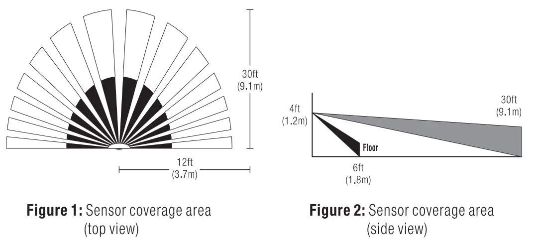
COVERAGE AREA
- The sensor must have a clear and unobstructed view of the area. If an object blocks the sensor’s lens, the sensor may not detect motion and may turn the lights or fan off even if someone is in the area. Windows, glass doors, and other transparent barriers will obstruct the sensor’s view and prevent motion detection.
- The coverage area data is measured under the best temperature condition (20 to 25° C), and a higher or lower temperature may not lead to an ideal coverage area (see figures 1 and 2).

SWITCH OVERVIEW
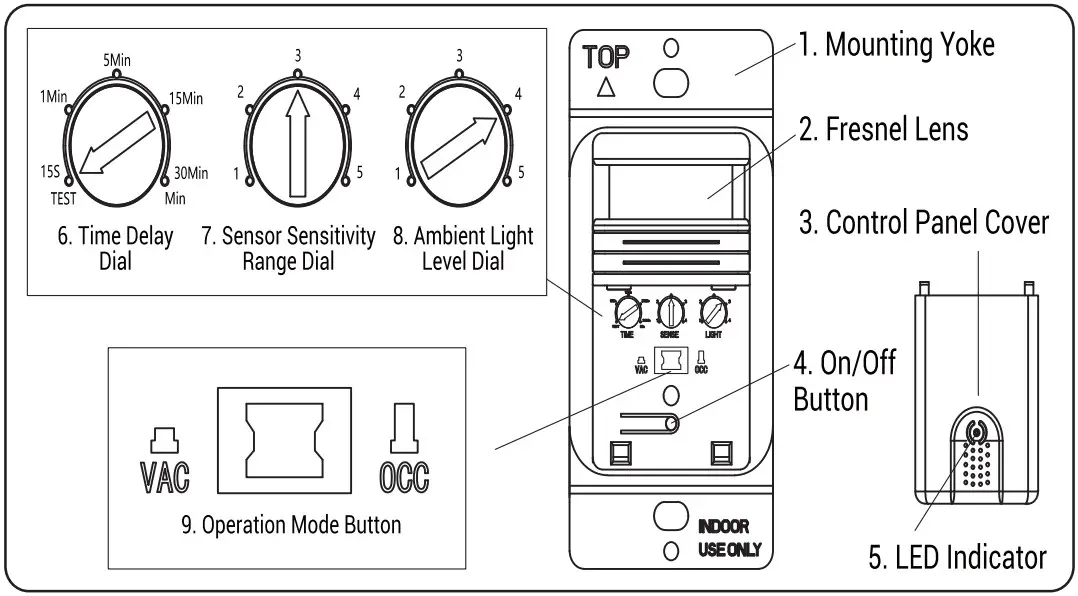
Figure 3: YM21 08T Series sensor switch diagram
| 1. Mounting Yoke | Lets you mount the switch to the wall. |
| 2. Fresnel Lens | Detects motion. |
| 3. Control Panel Cover | Covers the switch’s adjustment dials. Remove the cover to see the dials. |
| 4. On/Off Button | Lets you turn the light or fan on or off. |
| 5. LED Indicator | Indicates when the sensor detects motion. The green LED lights the On/Off button while the lights or fan are off. When they are on, the LED turns off. |
| 6. Time Delay Dial | Controls how long the light or fan stays on after no motion is detected. |
| 7. Sensor Sensitivity Range Dial | Adjusts the sensitivity setting to avoid unwanted detection such as hallway traffic or adjacent movement. |
| 8. Ambient Light Level Dial | Prevents the sensor from automatically turning the lights or fan on if the area has enough ambient lighting. |
| 9. Operation Mode Button | The sensor has two positions that correspond to operation modes: vacancy (when the button is pressed) and occupancy (when the button is released). |
BEFORE INSTALLATION
![]() WARNING:
WARNING:
- Before installing the YM2108T Series sensor switch, disconnect power to the wall switch box by turning off the circuit breaker or removing the fuse for the circuit.
- For supply connections use 18AWG or larger wires suitable for at least 75°C
- Tightly secure the ground wire to ensure that the sensor functions properly.AVERTISSEMENT:
- avant d’ installer I’interrupteur du capteur de la serieYM2108T, debranchez (‘alimentation du boitier d’interrupteur mural en eteignant le disjoncteur ou en retirant le fusible du circuit.
- Pour les connexions d’alimentation, utilisez des fils de 1 8AWG ou plus adaptes a au moins 75 ° C
- fixez fermement le fil de terre pour vous assurer que le capteur fonctionne correctement.
IMPORTANT:A neutral wire is required for the switch to work properly. If the existing wiring does not match the description for a two-pole circuit, or if you do not have a neutral wire, consult a qualified electrician.
IMPORTANT:Un fil neulre est necessairepourque rintemyteur fonctionnecorrectement. Si le cablage existant ne correspond pas A la description d’un circuit bipolaire, ou si vous n’avez pas de fil neutre, consultez un electricien qualifie.)
- These instructions describe only the 3-way circuit applications.
- For information about other applications,
- consult technical support.1. Prepare the switch box
- After the power is turned OFF at the circuit breaker box, remove the existing wall plate and mounting screws. Pull the old switch out from the wall box.2. Identify the type of circuit
- You may connect the YM2108T to a single pole or multi-way circuit. If you are unable to clearly identify some or all of the wires mentioned in this manual, you should consult with a qualified electrician.
- In a3-way circuit (see Fig. 4), two traveler wires connect to both switches. Another wire provides power from the circuit box to one of the switches. A wire connects from one switch to the load. A ground wire may also be connected to a ground terminal on the old switches. A neutral wire should also be present in both wall boxes.
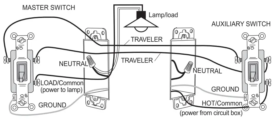
Figure 4: typical 3-way switch wiring
INSTALLATION AND WIRING
OPTION A
WIRING YM2108T WITH REGULAR 3-WAY SWITCH
Wire according to the wiring diagram below (see figure 5).
IMPORTANT: The Y1112108T must be installed in the wiring wall box that connects to the load.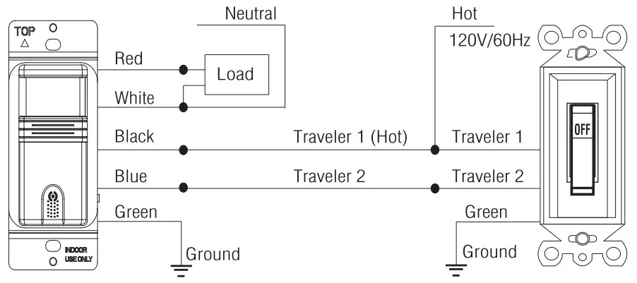 Figure 5: Wire diagram for YM2108T with regular 3-way wall switch
YM2108T MOTION SENSOR INSTALLATION
- Connect the green or non-insulated (copper) GROUND wire in each wiling box to Me green terminal on YM2108T
- Connect the NEUTRAL wire from the circuit and from the lamp (LOAD) to the white wire on the YM2108T
- Connect the1RAVELER 1 wire(which Connect two switch) coming from the Regular Switch wiring box to the black wire of the 11421081.
- Connect the lamp power (LOAD) to the red wire on the YM2108T.
- Connect the TRAVELER 2 wire to the other side of the Regular Switch and to the blue wire of the YM2108T
Regular Switch Part
- Connect the green or non-insulated (copper) GROUND wire in each wiring box to the green terminal on a Regular Switch.
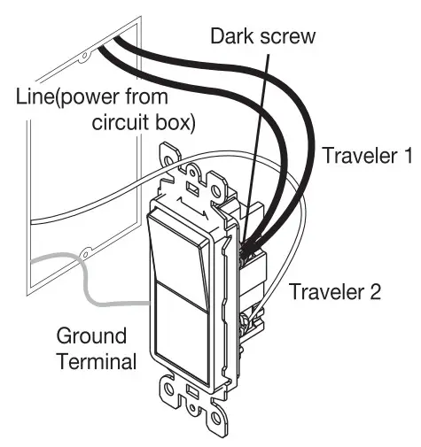
- Connect the POWER wire(HOT) and TRAVELER 1 wire to the Regular Switch common screw (dark screw).
- Connect TRAVELER 2 to Regular Switch screw.
WIRING YM2108T WITH ANOTHER YM2108T 3-WAY SWITCH
Wire according to the wiring diagram below (see figure 6).
- Connect the green or non-insulated (copper) GROUND wire from the circuit to the green wire on each YM2108T
- Connect the NEUTRAL wire from the circuit and from the lamp (LOAD) to the white wire on the 12108T.
- Connect the NEUTRAL wire from the circuit in the other wiring box to the white wire on the auxiliary W.12108T.
- Connect the power wire from the circuit box (HOT) to the black wire on theauxiliaryYM21081 and to the TRAVELER 1 wire.
- Connect the TRAVELER 1 wire from the black wire of the auxiliary YM2108T to the black wire of the Y142108T
- Connect the lamp power (LOAD) to the red wire on the YM2108T.
- Cap the red wire on the auxiliaryYM2108T.
- Connect the TRAVELER 2 wire coming from the blue wire of another YM2108T to the blue wire of the YM21081 that you are wiring.
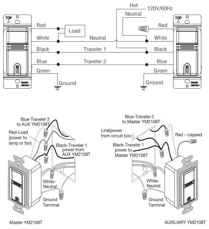
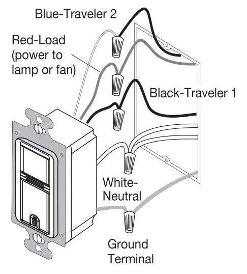
Figure 6: Sensowientatico. wire connections. and wall box assembly when wiring the 1112108T Series sensor switch with another YM2108T Series sensor switch
Finish Installation
- Insert the switch into the wall box by positioning the lens at the top and the On/Of f button at the bottom.
- Secure the switch to the wall box with the screws provided. 3. Attach the new cover plate and secure it to the wall box with the screws provided.
- Restore the power to the circuit by turning on the breaker or replacing the fuse.
ADJUSTMENT AND PROGRAMMING
To program the sensor, first remove the cover:
- Insert a small flathead screwdriver into the notch located on the bottom of the cover below the sensor.
- Gently lift the screwdriver upward to unlatch the cover (see figure 7).
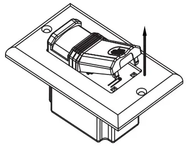 Figure 7: Lift the screwdriver upward to open the cover.
Vacancy: In vacancy mode (manual on/off, auto of ff, press the On/Off button to turn the light or fan on or off like you would a standard switch. The YM2106T Series sensor switch automatically turns off the lights or fan after the time delay.
Note: In VAC mode, it is closed manually and must be opened manually. If it’s sensed in 30 seconds after the automatic closing, it will still be automatically opened. After 30 seconds. need to manually turn on the switch.
Occupancy: In occupancy mode (auto on, auto off with auto-reset), the lights or fan turn on automatically when the space is occupied. The theYM2108T Series sensor switch automatically turns off the lights or fan after the time delay. If the lights or fan are turned off manually, automatic on is re-enabled when no motion is detected for one minute. This way, the lights or fan will remain off if they were deliberately turned off.
Note: In OCCmode. if the switch is manually turned off, the switch will work after 15 seconds.
Adjust the Time DelayThe Time Delay Dial, labeled as TIME, controls how long the light or fan stays on after no motion is detected. The minimum setting is 15 seconds (fully counterclockwise) and the maximum setting is 30 minutes (fully clockwise). Adjust the setting as desired for your area.
Adjust the Sensitivity Range of the Sensor
- The Sensor Sensitivity Range Dial, labeled as SENSE. lets you adjust the sensor to avoid unwanted motion detection such as hallway traffic.
- To decrease sensitivity. tum the setting counterclockwise. To Increase sensitivity, turn the setting clockwise. The sensor’s default setting is 3 (75%). You can adjust it from setting 1 (50%) to setting 5 (100%).
 report this ad
Adjust the Ambient Light Level
The Ambient Light Level Dial, labeled as LIGHT. lets you adjust the sensor to detect whether other light sources (such as sunlight) are enough to light the space without turning on the lights. If you would like the sensor to consider the amount of ambient light in your area, turn the dial counterclockwise. If you would rather not use the ambient light level, leave it on the maximum, default setting (5). This will allow the sensor to turn the light on and off regardless of ambient light.
TROUBLESHOOTING
Lights or Fan Will Not Turn OnPush the On/Off button. The load should turn on. If not:
- Check the light bulb and/or motor switch on the fan.
- Turn off the power to the circuit and check the wire connections.
Lights or Fan Will Not Turn ON
- Ensure that no motion is occurring in the coverage area until the set time period.
- Ensure that the sensor is at least 6 ft (2 m) away from devices that are a significant heat source (e.g., heater. heater vent. and high wattage light bulbs). Hot air currents and heat-radiating devices (such as 100W incandescent bulbs) can cause false detection.
- Push the On/Off button to Off. If the lightsor fan do not tum off, turn off power to the circuit and check wire connections.
Lights or Fan Rim ON Too QuicklyThe time delay or sensitivity range may be Improperly set. Refer to the adjustment and Programming section.
Lights or Fan Turn on When Movement Is Detected in Adjacent AreasIf the sensor’s location gives it a view of other areas or hallways, the lights will turn on when motion is detected in those areas. Try adjusting the sensitivity range (refer to the Adjustment and Programming section). You may need to move the sensor to another location.
Lights or Fan Turn on When the Area is UnoccupiedThe sensor may be mounted too closely to an air conditioning or heating vent. Move the sensor to another location or close the vent.
[xyz-ips snippet=”download-snippet”]