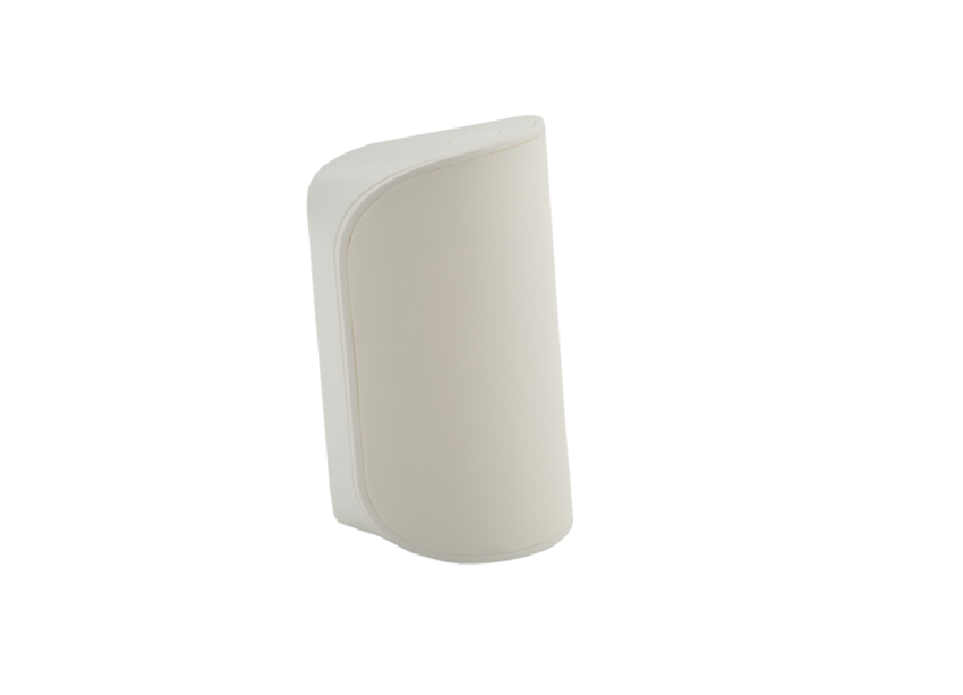
Ecolink Wireless PIR Motion Sensor with Pet Immunity WST-742
Specifications
| Frequency: | 345 MHz |
| Operating Temperature: | 32°-120°F (0°-49°C) |
| Operating Humidity: | 5-95% RH non-condensing |
| Battery: | 1x CR123A, Lithium 3V DC |
| Battery Life: | up to 5 Years |
| Compatibility: | Honeywell and 2GIG receivers |
| Pet Immunity: | Up to 50 lbs |
| Supervisory Interval: | Approximately 60 minutes |
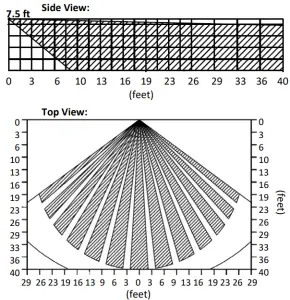
| Coverage Area: | 40 feet by 40 feet, 90° angle |
| Light Immunity: | 2000 Lux |
| Coverage Pattern: |
Package Contents
- 1x Sensor
- 4x Screws & Wall Anchor
- 2x Sensor Case Screw
- 1x Manual
- 1x Sensitivity Jumper
- 1x Back Mounting 2-Sided Adhesive Tape
- 1x CR123A battery (installed)
- 2x Side Mounting 2-Sided Adhesive Tape
- 2x Side Mounting 2-Sided Adhesive Tape
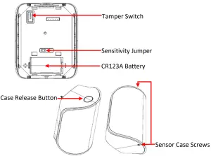
Component Identification
Enrollment
To enroll the motion sensor, set your panel into programming mode according to the panel manufacturer’s instruction. When prompted by the panel, enter the 7 digit serial number printed on the sensor label. Make sure the loop number is set to Loop 1.
Some panels can enroll your sensor by capturing the serial number transmitted by your sensor. The sensor can be enrolled by triggering wireless transmissions. Place the sensor into walk test mode by holding down the sensor’s tamper switch while inserting the battery. The red LED will begin to flash for 30 seconds. When the LED stops flashing, the sensor can be triggered by waving your hand in front of the motion sensor. The sensor will transmit every time motion is detected. Trigger the motion sensor as many times as necessary until the panel recognizes the sensor’s serial number. Make sure the loop number is set to Loop 1.
Mounting
Mount the motion sensor at 7.5 feet (2.3 meters) above the floor. Press the case release button to separate the front and back sensor case. The back case gives access to both the flush mount and corner mount screw knock outs. Remove the appropriate knockouts and use the included screws to mount in the desired mounting location. It is recommend to ensure there is a tight seal around the knockouts to prevent bugs from entering the sensor and causing false alarms. Replace the front sensor cover to snap shut and screw in the sensor case screws on the top and bottom of the back sensor case. The WST-742 intrusion detection unit shall be installed in accordance with the Standard for Installation and Classification of Residential Burglar Alarm Systems, CAN/ULC-S310. The WST-742 is intended to be installed in accordance with the Standard for Installation and Classification of Residential Burglar Alarm Systems, UL1641.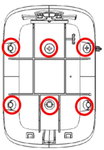
Sensitivity Jumper Settings
For normal sensitivity motion detection leave the jumper in the default setting (on). Remove the jumper if increased sensitivity to movement is desired.
Walk Test Mode
Walk test mode can be used to test the motion sensor detection coverage area. To enter walk-test mode hold down the tamper button while inserting the battery. The red LED will begin to flash indicating that the motion sensor is warming up. After 30 seconds the LED no longer flashes and the motion sensor is ready to detect motion. The LED will illuminate each time motion is detected. Once the LED goes out, the sensor is ready to detect motion again. Walk test mode ends after twenty motion detections or if no motion is seen for one minute. It is recommended that the WST-742 PIR is tested monthly to ensure proper function.
Operation
During normal operation, the LED will not turn on even if motion is detected. This is done to maximize battery life. Furthermore, when motion is detected and a signal is transmitted to the panel, the sensor will not transmit again for a period of three minutes. The WST-742 is an intrusion detection unit and shall provide for connection into an alarm system in accordance with the Standard for the Installation and Classification of Residential Burglar Alarm Systems, CAN/ULC-S310.
Maintenance – Replacing the Battery
When the battery is low, a signal will be sent to the control panel. To insert or replace the battery:
- Remove the front cover to expose the battery
- Remove the backplate using a bottom-to-top lifting motion.
- Remove the CR123A lithium battery. Note the correct orientation of the battery as shown on the sensor cover plate. Always match the plus (+) sign on the battery with the flat side of the compartment and the minus (-) sign on the battery with the spring side.
- Replace the front cover.WARNING: Failure to follow these warnings and instructions can lead to heat generation, rupture, leakage, explosion, fire, or other injury, or damage. Do not insert the battery into the compartment in the wrong direction. Always replace the battery with the same or equivalent type (see Specifications on page 1). Never recharge or disassemble the battery. Never place the battery in fire or water. Always keep batteries away from small children. If batteries are swallowed, promptly see a doctor.
- Always dispose and/or recycle used batteries in accordance with the hazardous waste recovery and recycling regulations for your location. Your city, state, or country may also require you to comply with additional handling, recycling, and disposal requirements.
Environmental and Other Useful Information
- While the PIR is a highly reliable intrusion detection device, it does not guarantee against burglary. Any intrusion device is subject to a “failure to warn” for a variety of reasons. Consider the following when installing and setting up the PIR:
- This PIR has built-in protection to keep bugs from getting into the sensor area and causing false alarms. Note that this protection does not prevent insects from crawling across the lens of the PIR, which could trigger the PIR.
- Infrared energy can be reflected off any glossy surfaces such as mirrors, windows, floors, or counter tops with glossy finish, and slick-finished concrete. Some surfaces reflect less than others (e.g. the PIR can see a change in infrared energy off of reflective surfaces even if the heat or cold source is not within the PIR detection pattern).
- Windows reflect infrared energy. They also allow sunlight or light from other sources (e.g., cars) to pass through to the PIR. The PIR can detect these changes in infrared energy. For example, if sunlight passing through a window shines onto a hardwood floor and the change in infrared energy is quick enough, the PIR can trigger an alarm. The same applies if the PIR area includes a window, even though the pattern of protection cannot “see” through glass. Lights from a passing car can also pass through the window at night and shine directly into the PIR’s lens.
- Heating and air conditioning ducts are also important because if they blow air onto an object within the field of the PIR’s view, the temperature of that object could change quickly enough for the PIR to “see” a change in infrared energy. PIR’s cannot see air current, only the change in temperature of a physical object.
- The PIR senses change in temperature. However, as the ambient temperature of the protected area approaches the temperature range of 95° to 120° F, the detection performance of the PIR decreases.
- Ensure that the area you wish the PIR to cover is free of obstructions (for example, curtains, screens, plants, and so on.) that may block the pattern of coverage.
- Anything that can sway or move due to air current can cause a change in infrared energy within the fields of view. Drafts from doors or windows can cause this to happen. Plants, balloons, curtains, and hanging baskets should never be left in the PIR’s field of view.
- Do not mount the PIR on a surface that allows for any vibration. Vibrations not only cause the PIR to move a little, but it also causes the fields of view in a room to move with respect the PIR. A little vibration can cause havoc with the PIR’s field of view, thus the PIR may see a change in energy and trigger the alarm.
- An installation often requires that the PIR is aimed at the door. The PIR may detect door movement before the door contact can initiate an entry delay, causing the alarm to trigger. If you install the PIR facing a door, then while programming the PIR, choose an appropriate sensor/zone type.
- The PIR ONLY detects intrusion within the pattern of coverage. · The PIR does not provide volumetric area protection. · The PIR creates multiple beams of protection. Intrusion can only be detected in unobstructed areas covered by those beams.
- The PIR cannot detect motion or intrusion that occurs behind walls, ceilings, floors, closed doors, partitions, glass doors, or windows
- Tampering with, masking, painting, or spraying of any material on the PIR lens or any part of the optical system can impair detection ability.
- The PIR, like other electrical devices, are subject to component failure. Even though the PIR is designed to last as long as 10 years, the electronic components are subject to failure.
FCC Compliance Statement
This device complies with part 15 of the FCC Rules. Operation is subject to the following two conditions:(1) This device may not cause harmful interference, and(2) this device must accept any interference received, including interference that may cause undesired operation.This equipment has been tested and found to comply with the limits for Class B digital devices, pursuant to Part 15 of the FCC Rules. These limits are designed to provide reasonable protection against harmful interference in a residential installation. This equipment generates uses and can radiate radio frequency energy and, if not installed and used in accordance with the instruction manual, may cause harmful interference to radio communications. However, there is no guarantee that interference will not occur in a particular installation. If this equipment does cause harmful interference to radio or television reception, which can be determined by turning the equipment off and on, the user is encouraged to try to correct the interference by one or more of the following measures:
- Re-orient or relocate the receiving antenna
- Increase the separation between the equipment and receiver
- Connect the equipment to an outlet on a different circuit from the receiver
- Consult the dealer or an experienced radio/TV contractor for help.
Warning: Changes or modifications not expressly approved by Ecolink Intelligent Technology Inc. could void the user’s authority to operate the equipment.
This device complies with Industry Canada licence-exempt RSS standard(s). Operation is subject to the following two conditions:(1) this device may not cause interference, and(2) this device must accept any interference, including interference that may cause undesired operation of the device.FCC ID: XQC-WST742___________________ IC: 9863B-WST742
Warranty
Ecolink Intelligent Technology Inc. warrants that for a period of 2 years from the date of purchase that this product is free from defects in material and workmanship. This warranty does not apply to damage caused by shipping or handling, or damage caused by accident, abuse, misuse, misapplication, ordinary wear, improper maintenance, failure to follow instructions or as a result of any unauthorized modifications. If there is a defect in materials and workmanship under normal use within the warranty period Ecolink Intelligent Technology Inc. shall, at its option, repair or replace the defective equipment upon return of the equipment to the original point of purchase. The foregoing warranty shall apply only to the original buyer, and is and shall be in lieu of any and all other warranties, whether expressed or implied and of all other obligations or liabilities on the part of Ecolink Intelligent Technology Inc. neither assumes responsibility for, nor authorizes any other person purporting to act on its behalf to modify or to change this warranty, nor to assume for it any other warranty or liability concerning this product. The maximum liability for Eco link Intelligent Technology Inc. under all circumstances for any warranty issue shall be limited to a replacement of the defective product. It is recommended that the customer check their equipment on a regular basis for proper operation.
2055 Corte Del Nodal Carlsbad, CA 92011 1-855-632-6546 www.discoverecolink.com
 report this ad
References
[xyz-ips snippet=”download-snippet”]