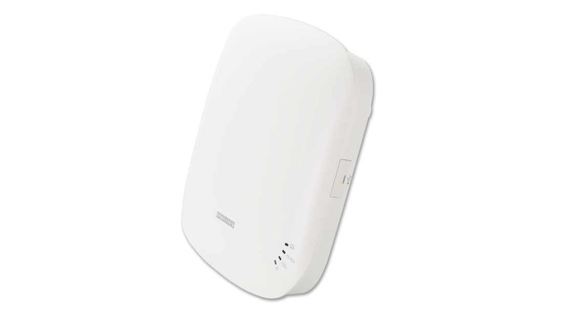
 Quick Start GuideDual-Band Wi-Fi 6 Indoor Access PointEAP102
Package Contents
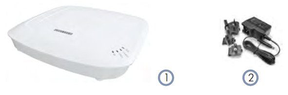
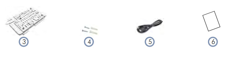
- EAP102 access point
- AC power adapter with international socket converters
- Mounting bracket accessory
- Screw kit–2 screws and 2 plugs
- (Optional) Console cable–RJ-45 to DB-9
- QR code card
Overview
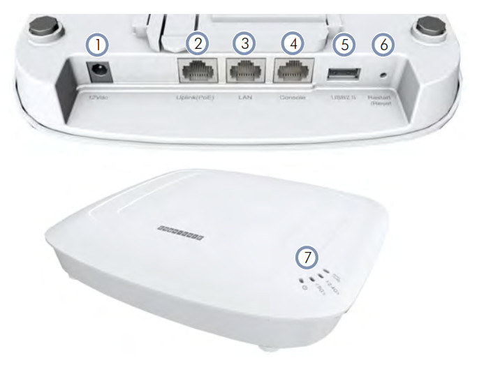
- 12 VDC power input
- Uplink(PoE) Port: 2.5Gbps connection to 802.3at PoE LAN device.
- LAN Port: 2.5Gbps connection to LAN devices.
- Console port
- USB 2.0 port (reserved for future use)
- Restart/Reset button:• A quick press restarts the system.• A 5 second press resets to factory defaults.
- System LED Indicators:• Uplink(PoE): On (link), Blinking (traffic)• 2.4G: On (radio on), Blinking (traffic)• 5G: On (radio on), Blinking (traffic)• Status: On (power OK), Blinking (boot up)
Installation
 Warning: For indoor use only. The access point, AC power adapter, and all connected cables are not for outdoor use.
Mount the AP
a. Mounting on a Wall
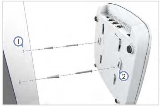
1. At the installation location on the wall, set two screws in the wall 128 mm (5.0 in.) apart. Use the wall plugs and screws included in the screw kit.2. Slide the AP’s wall mounting slots down onto the screws so that the unit is secure.
b. Mounting on a T-Bar
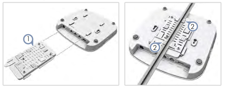
1. Slide the bracket accessory onto the base of the AP until it clicks into its locked position.2. Position the ceiling-mount clip holders on either side of the T-bar, and then turn the AP until the two clips lock it to the T-bar.
![]() Note: The AP mounting supports two different sizes of suspended ceiling T-bars. The position illustrated above is for 24.5 mm bars. Use the position at a 90 degrees angle for 15 mm bars.
Note: The AP mounting supports two different sizes of suspended ceiling T-bars. The position illustrated above is for 24.5 mm bars. Use the position at a 90 degrees angle for 15 mm bars.
Connect Cables
a. Connect LAN Cables
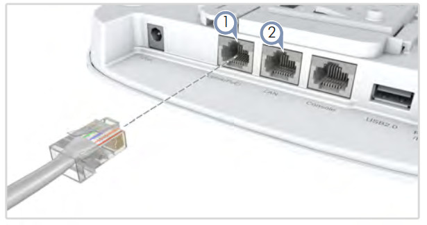
- Connect Category 5e or better cable to the Uplink(PoE) 2.5GBASE-T RJ-45 port. When connected to a PoE source, the Uplink(PoE) port connection provides power to the unit.
- (Optional) Connect a local LAN switch or computer to the LAN 2.5GBASE-T RJ-45 port.
b. (Optional) Connect AC Power Adapter
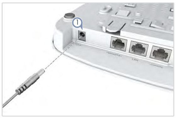
1. Connect the AC power adapter to the DC power jack on the AP and then plug the adapter into a nearby AC power source.
Check AP LEDs
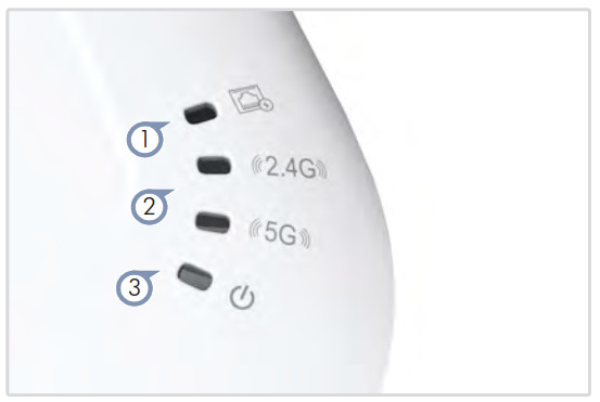
- Uplink(PoE) LED — on green for a valid link.
- 2.4G and 5G LEDs — on green for radio enabled.
- Power/Status LED — on green for normal operation.
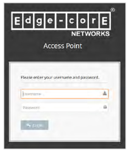
4 Connect to the Web User Interface
- Connect a PC directly to the AP’s LAN port.
- Set the PC IP address to be on the same subnet as the AP LAN port default IP address. (The PC address must start 192.168.2.x with subnet mask 255.255.255.0.)
- Enter the AP’s default IP address of 192.168.2.1 into the web browser address bar.
- Log in to the web interface using default settings: Username = admin Password = admin
![]() Note: To connect to the web interface using the Uplink(PoE) port, the IP address is automatically assigned through DHCP by default. If a DHCP server is unreachable, the Uplink(PoE) port reverts to a fallback IP address of 192.168.1.10.
Note: To connect to the web interface using the Uplink(PoE) port, the IP address is automatically assigned through DHCP by default. If a DHCP server is unreachable, the Uplink(PoE) port reverts to a fallback IP address of 192.168.1.10.
Note: To reset the AP to factory default settings, press and hold down the AP’s Restart/Reset button for 5 seconds.
Safety and Regulatory Information
FCC Class B
This equipment has been tested and found to comply with the limits for a Class B digital device, pursuant to Part 15 of the FCC Rules. These limits are designed to provide reasonable protection against harmful interference in a residential installation. This equipment generates, uses and can radiate radio frequency energy and, if not installed and used in accordance with the instructions, may cause harmful interference to radio communications. However, there is no guarantee that interference will not occur in a particular installation. If this equipment does cause harmful interference to radio or television reception, which can be determined by turning the equipment off and on, the user is encouraged to try to correct the interference by one of the following measures:
- Reorient or relocate the receiving antenna
- Increase the separation between the equipment and receiver
- Connect the equipment into an outlet on a circuit different from that to which the receiver is connected
- Consult the dealer or an experienced radio/TV technician for help
FCC Caution: Any changes or modifications not expressly approved by the party responsible for compliance could void the user’s authority to operate this equipment.This device complies with Part 15 of the FCC Rules. Operation is subject to the following two conditions: (1) This device may not cause harmful interference, and (2) this device must accept any interference received, including interference that may cause undesired operation.
For product available in the USA/Canada market, only channel 1~11 can be operated. Selection of other channels is not possible.
IMPORTANT NOTE:
FCC Radiation Exposure Statement:This equipment complies with FCC radiation exposure limits set forth for an uncontrolled environment. This equipment should be installed and operated with minimum distance 24 cm between the radiator and your body.
CE Statement
This equipment complies with EU radiation exposure limits set forth for an uncontrolled environment. This equipment should be installed and operated with minimum distance 20 cm between the radiator and your body.
The device is restricted to indoor use only when operating in the 5150 to 5350 MHz frequency range.All operational modes:
2.4 GHz: 802.11b, 802.11g, 802.11n (HT20), 802.11n (HT40), 802.11ac (VHT20), 802.11ac (VHT40), 802.11ax (HE20), 802.11ax (HE40)
5 GHz: 802.11a, 802.11n (HT20), 802.11n (HT40), 802.11ac (VHT20), 802.11ac (VHT40), 802.11ac (VHT80), 802.11ax (HE20), 802.11ax (HE40), 802.11ax (HE80)The frequency and maximum transmitted power limit in EU are listed as below:2412-2472 MHz: 20 dBm5150-5350 MHz: 23 dBm5500-5700 MHz: 30 dBm

| AT | BE | BG | CH | CY | CZ |
| DE | DK | EE | EL | ES | FI |
| FR | HR | HU | IE | IS | IT |
| LI | LT | LU | LV | MT | NL |
| NO | PL | PT | RO | SE | SI |
| SK | TR | UK |
The abbreviations of the countries, as prescribed in above table, where any restrictions on putting into service or any requirements for authorization of use exist.
 CE Mark Declaration of Conformance for EMI and Safety (EEC)This information technology equipment is in compliance with the Directive 2014/53/EU and Directive 2014/35/EU.The Declaration of Conformity (DoC) can be obtained from www.edge-core.com -> support -> download.
Warnings and Cautionary Messages
Warning: This product does not contain any serviceable user parts. Warning: Installation and removal of the unit must be carried out by qualified personnel only. Warning: When connecting this device to a power outlet, connect the field ground lead on the tri-pole power plug to a valid earth ground line to prevent electrical hazards. Caution: Wear an anti-static wrist strap or take other suitable measures to prevent electrostatic discharge when handling this equipment.Caution: Do not plug a phone jack connector in the RJ-45 port. This may damage this device.Caution: Use only twisted-pair cables with RJ-45 connectors that conform to FCC standards.
Hardware Specifications
| AP Chassis | |
| Size (WxDxH) | 20`1 x 195 x 39.8 mm (7.91 x 7.68 x 1.57 in.) |
| Weight | 0.7 kg (1.54 lb) |
| Temperature | Operating: 0° C to 45° C (32° F to 113° F) Storage: -40° C to 70° C (-40° F to 158° F) |
| Humidity | Operating: 5% to 95% (non-condensing) |
| Network Interfaces | |
| Ports | Uplink(PoE) RJ-45 Port: 2.5GBASE-T, PoE PDLAN RJ-45 Port: 10/100/1000/2.5GBASE-T |
| 2.4 GHz Radio | IEEE 802.11b/g/n/ac/ax |
| 5 GHz Radio | IEEE 802.11a/n/ac/ax |
| Bluetooth Radio | IEEE 802.15.1 |
| Radio Frequencies | 2.4 2.4835 GHz (US, Canada, ETSI) 5.15 5.25 GHz (lower band) US/Canada, Europe5.725 5.825 GHz (upper band) US/Canada |
| Power Specifications | |
| PoE Input Power | 24 W max, 48 VDC55 VDC; 802.3at-compliant |
| AC Power Adapter | AC Input: 100240 VAC, 50-60 Hz DCOutput: 12 VDC, 2 A |
| Regulatory Compliances | |
| Radio | EN300 328 V2.2.2 (2019-07)EN301 893 V2.1.1(2017-03)47 CFR FCC Part 15.24747 CFR FCC Part 15.407NCC LP0002MIC certification Rule, Article 2 Paragraph 1 Item19 MIC certification Rule, Article 2 Paragraph 1 Item19-3 and 19-3-2 |
| Emissions | EN 301 489-1 V2.1.1 (2017-02)EN 301 489-17 V3.1.1 (2017-02)AS/NZS CISPR 32:2015, Class B47 CFR FCC Rules and Regulations Part 15Subpart B, Class B Digital DeviceCNS 13438MIC certification Rule, Article 9 & Article 34 |
| Safety | Low Voltage Directive (2014/35/EU, formerly 2006/95/EC, formerly 73/23/EEC) CNS 14336-1 IEC/EN 62368-1, IEC/EN 60950-1 |
| Taiwan RoHS | CNS 15663 |
[xyz-ips snippet=”download-snippet”]