![]()
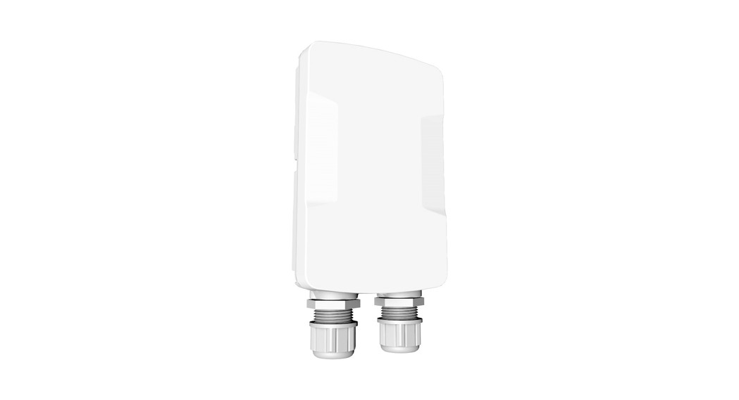
Quick Start Guide60GHz Access PointMLTG-CN
Package Contents

|
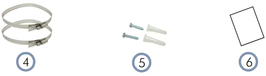
| 1. 60GHz Access Point MLTG-CN | 4. 2 x Steel-band clamps for pole mount (3 inch diameter max.) |
| 2. 1 x 24 W PoE injector | 5. 2 x Screws with nylon expansion plugs for wall mount |
| 3. 1 x Power cord | 6. Documentation QR-code card |
Overview
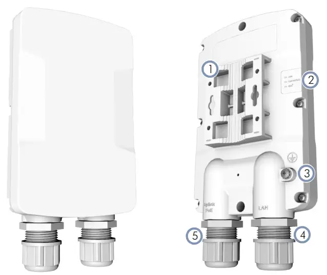
- Integrated pole and wall mounting bracket.
- System LED Indicators:■ LAN: On (LAN port link), Blinking (activity).■ Uplink(PoE): On (Uplink PoE port link), Blinking (activity). Slow blink during system boot up.■ 60G: On (60GHz wireless link), Blinking (activity).
- Grounding Screw: For ground wire connection.
- LAN Port: Connects to LAN devices.
- Uplink PoE Port: Connects to PoE injector and LAN devices.
Installation
 Warning: For a safe and reliable installation, use only the accessories and screws provided with the device. The use of other accessories and screws could result in damage to the unit. Any damages incurred by using unapproved accessories are notcovered by the warranty.
Avertissement: Pour une installation sûre et fiable, utilises uniquement les accessoires et les vis fournies avec l’appareil. L’utilisation d’autres accessoires et vis pourrait endommager l’appareil. Les dommages causés par l’utilisation d’accessoiresnon approuvés ne sont pas couverts par la garantie.
Ground the MLTG-CN
 Ground the MLTG-CN by connecting a ground wire to the grounding point on the MLTG-CN and to the nearby good earth.
Make Network Connections
 RJ-45 Ports
- Connect outdoor-rated Category 5e or better cable to the 1000BASE-T RJ-45 Uplink PoE port. Be sure to use the included weatherproof RJ-45 port cover.
- (Optional) Connect a local LAN switch or computer to the LAN 1000BASE-T RJ-45 port. Be sure to use the included weatherproof RJ-45 port cover.
![]() Note: The Uplink PoE port connection provides PoE power to the unit.
Note: The Uplink PoE port connection provides PoE power to the unit.
Mount the MLTG-CN
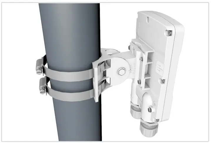
a. Mount on a Pole

- Feed the steel-band clamps through the pole-mount bracket points on the back of the MLTG-CN and then lightly fasten them around the pole.
- Align the MLTG-CN antenna with a nearby Distribution Node before tightening the clamps securely.
b. Mount on a Wall
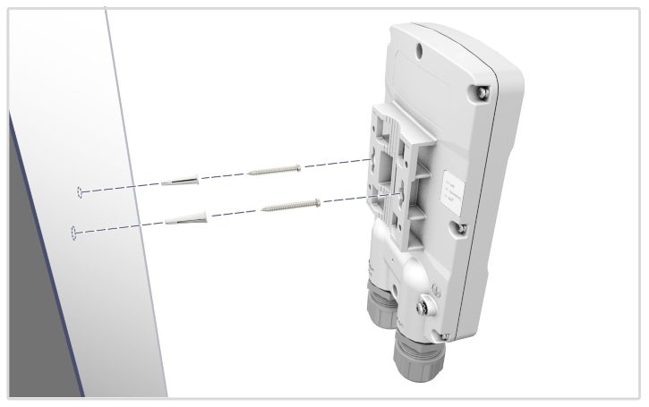
- Drill two holes in the wall for the included expansion plugs. Insert the expansion plugs and the two screws in the holes.
- Align the MLTG-CN mounting bracket with the screws and then slide the device down until it snaps into its secured position.
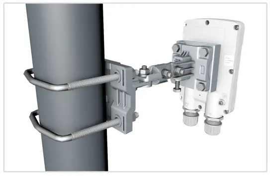
c. Use Precision Brackets (Optional)
Two optional precision brackets (ordered separately) are designed for wall and pole mounting and provide additional degrees of movement for antenna alignment.
 Connect Power
 Connect the other end of the outdoor-rated Ethernet cable from theUplink (PoE) port to the 802.3at-compliant power injector.
Verify Power is On
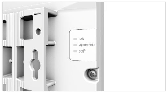 Check the LEDsThe Uplink (PoE) LED should blink slowly during boot-up and be on or blinking when operating normally.
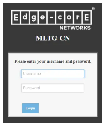
Access the Web User Interface
- Connect a PC directly to the MLTG-CN’s LAN port.
- Set the PC IP address to be on the same subnet as the MLTG-CN LAN port default IP address. The PC address must start 192.168.2.x with subnet mask 255.255.255.0).
- Enter the MLTG-CN’s default IP address of 192.168.2.1 into the web browser address bar.
- Log in to the web interface using default settings:Username = adminPassword = admin
Safety and Regulatory Information
FCC Class BThis equipment has been tested and found to comply with the limits for aClass B digital device, pursuant to Part 15 of the FCC Rules. These limits are designed to provide reasonable protection against harmful interference in a residential installation. This equipment generates, uses, and can radiate radio frequency energy and, if not installed and used in accordance with the instructions, may cause harmful interference to radio communications. However, there is no guarantee that interference will not occur in a particular installation. If this equipment does cause harmful interference to radio or television reception, which can be determined by turning the equipment off and on, the user is encouraged to try to correct the interference by one of the following measures:■ Reorient or relocate the receiving antenna■ Increase the separation between the equipment and receiver■ Connect the equipment into an outlet on a circuit different from that to which the receiver is connected■ Consult the dealer or an experienced radio/TV technician for help
FCC Caution: Any changes or modifications not expressly approved by the party responsible for compliance could void the user’s authority to operate this equipment.
This device complies with Part 15 of the FCC Rules. Operation is subject to the following two conditions: (1) This device may not cause harmful interference, and (2) this device must accept any interference received, including interference that may cause undesired operation.
This device is not to be operated on aircraft except for the conditions listed on FCC CFR? 15.255 (b).
IMPORTANT NOTE:FCC Radiation Exposure Statement:
This equipment complies with FCC radiation exposure limits set forth for an uncontrolled environment. This equipment should be installed and operated with a minimum distance of 22 cm between the radiator and your body.
IC StatementThis device contains license-exempt transmitter(s)/receiver(s) that comply with Innovation, Science, and Economic Development Canada’s license-exempt RSS(s). Operation is subject to the following two conditions: (1) This device may not cause interference. (2) This device must accept any interference, including interference that may cause undesired operation of the device.
IMPORTANT NOTE:IC Radiation Exposure Statement:
This equipment complies with IC RSS-102 radiation exposure limits set forth for an uncontrolled environment. This equipment should be installed and operated with a minimum distance of 22 cm between the radiator and your body.
CE StatementThis equipment complies with EU radiation exposure limits set forth for an uncontrolled environment. This equipment should be installed and operated with a minimum distance 20 cm between the radiator and your body.All operational modes:60 GHz: 802.11ad, 802.11ay
The frequency and maximum transmitted power limit in the EU are listed as below:57-66 GHz: 40 dBm

| AT | BE | BG | CH | CY | CZ |
| DE | DK | EE | EL | ES | Fl |
| FR | HR | HU | IE | IS | IT |
| LI | LT | LU | LV | WI | NL |
| NO | PL | PT | RO | SE | SI |
| SK | TR | UK |
The abbreviations of the countries, as prescribed in the above table, where any restrictions on putting into service or any requirements for authorization of use exist.
 CE Mark Declaration of Conformance for EMI and Safety (EEC) This information technology equipment is in compliance with the
Directive 2014/53/EU and Directive 2014/35/EU.
The Declaration of Conformity (DoC) can be obtained from www.edge-core.com -> support -> download.
Japan VCCI Statement
Warnings and Cautionary Messages
Warning: This product does not contain any serviceable user parts.Warning: Installation and removal of the unit must be carried out by qualified personnel only.Warning: When connecting this device to a power outlet, connect the field ground lead on the tri-pole power plug to avalid earth ground line to prevent electrical hazards.
 report this ad
 Caution: Wear an anti-static wrist strap or take other suitable measures to prevent electrostatic discharge when handling thisequipment.Caution: Do not plug a phone jack connector in the RJ-45 port. This may damage this device.Caution: Use only twisted-pair cables with RJ-45 connectors that conform to FCC standards.
Hardware Specifications
| AP Chassis | |
| Size (WxDxH) WeightTemperatureHumidity | 177.3 x 111.6 x 43 mm (6.98 x 4.39 x 1.69 in) 518 g (1.14 lb)Operating: -20° C to 55° C (-4° F to 131° F)Storage: -20° C to 70° C (-4° F to 158° F)Operating: 5% to 95% (non-condensing) |
| Network Interfaces | |
| Ports60 GHz | Uplink PoE RJ-45 Port: 1000BASE-T, PoE PDLAN RJ-45 Port: 1000BASE-T802.11ad/ay |
| Power Supply | |
| PoE Input PowerPower Consumption | 48 VDC (non-standard)24 Watts max |
| Regulatory Compliances | |
| Radio | EN 302 567 V2.1.1EN 62311 (MPE)47 CFR FCC Part 15.255RSS-210RSS-102 Issue 5 (MPE)MIC Article 2 Paragraph 1 Item 19—4-2 |
| Emissions | EN 301 489-1 V2.1.1EN 301 489-17 V3.1.1Part 15 subpart B Class B (ANSI C63.4-2014)ICES-003VCCI-CISPR 32 |
| Safety | EN 62368-1: 2014+ A11: 2017IEC 60950-1: 2005, AMD1: 2009, AMD2: 2013IEC 60950-22: 2016IEC 60529-1: 1989+ AMD1: 1999+ AMD2: 2013CSV (IP55) |
References
[xyz-ips snippet=”download-snippet”]