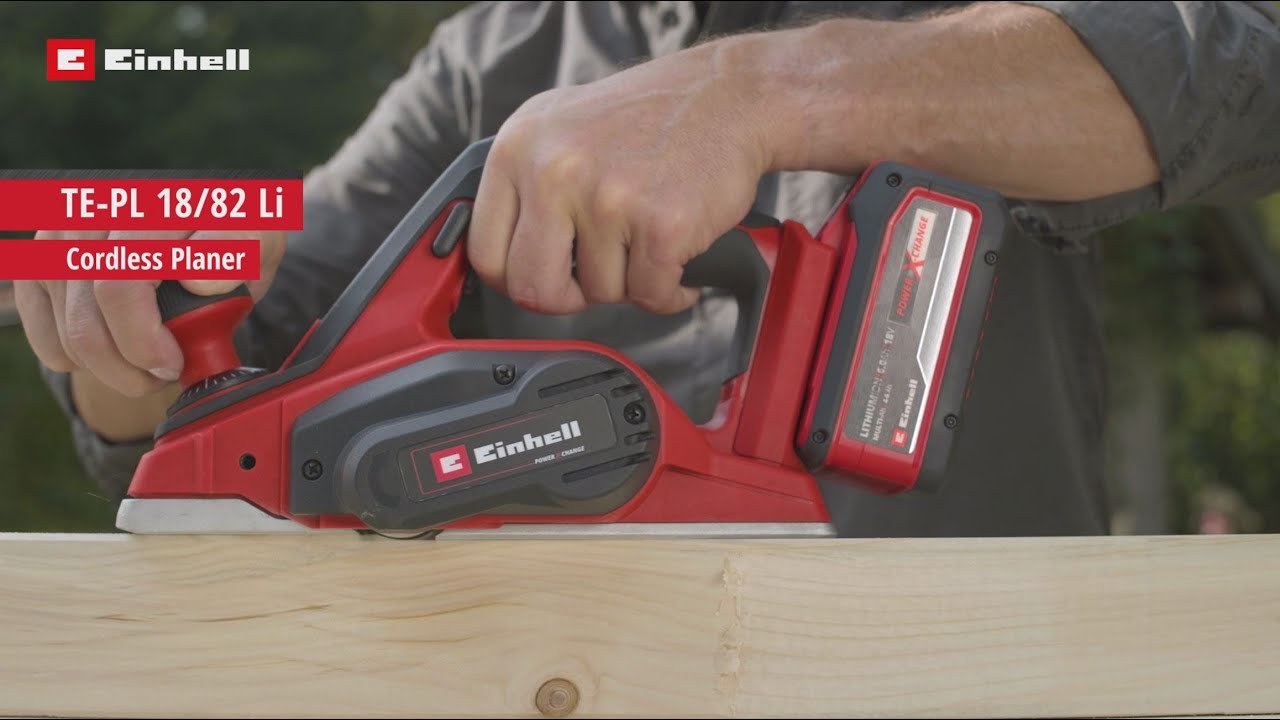
Einhell Cordless planer 
Danger! Read the operating instructions to reduce the risk of inquiry.Caution! Wear ear-muffs. The impact of noise can cause damage to hearing.Caution! Wear a breathing mask. Dust which is injurious to health can be generated when working on wood and other materials. Never use the device to work on any materials containing asbestos!Caution! Wear safety goggles. Sparks generated during working or splinters, chips and dust emitted by the device can cause loss of sight.Store the batteries only in dry rooms with an ambient temperature of +10°C to +40°C. Place only fully charged batteries in storage (charged at least 40%). (Not supplied).
Danger: When using the equipment, a few safety precautions must be observed to avoid injuries and damage. Please read the complete operating instructions and safety regulations with due care. Keep this manual in a safe place, so that the information is available at all times. If you give the equipment to any other person, hand over these operating instructions and safety regulations as well. We cannot accept any liability for damage or accidents which arise due to a failure to follow these instructions and the safety instructions.
Safety regulations
The corresponding safety information can be found in the enclosed booklet.Warning! Read all the safety information, instructions, illustrations and technical data provided on or with this power tool. Failure to adhere to the following instructions may result in electric shock, fi re and/or serious injury. Keep all the safety information and instructions in a safe place for future use.
Layout and items supplied
Layout (Fig. 1/2)
- Setting knob for the chip depth
- Chip ejector
- Safety lock-off
- On/Off switch
- Rear base plate
- Belt cover
- Parking soleplate
- Front base plate
- Thumb screw for step depth scale
- Step depth scale
- Parallel stop
- Wrench
Items supplied
Please check that the article is complete as specified in the scope of delivery. If parts are missing, please contact our service center or the sales outlet where you made your purchase at the latest within 5 working days after purchasing the product and upon presentation of a valid bill of purchase. Also, refer to the warranty table in the service information at the end of the operating instructions.
- Open the packaging and take out the equipment with care.
- Remove the packaging material and any packaging and/or transportation braces (if available).
- Check to see if all items are supplied.
- Inspect the equipment and accessories for transport damage.
- If possible, please keep the packaging until the end of the guarantee period.
Danger!The equipment and packaging material are not toys. Do not let children play with plastic bags, foils or small parts. There is a danger of swallowing or suff ocating!
- Cordless plane
- Parallel stop
- Wrench
- Step depth scale
- Original operating instructions
- Safety instructions
Proper use
The cordless plane is designed for planning, rebating and chamfering pieces of wood. The equipment is to be used only for its prescribe purpose. Any other use is deemed to be a case of misuse. The user / operator and not the manufacturer will be liable for any damage or injuries of any kind caused as a result of this. Please note that our equipment has not been designed for use in commercial, trade or industrial applications. Our warranty will be voided if the machine is used in commercial, trade or industrial businesses or for equivalent purposes.
Technical data
Motor power supply: ………………………….18 V d.c.Idling speed ………………………………… 15,000 rpmChip depth: …………………………………….. 0-2 mmRebate depth …………………………………… 0-8 mmPlane width: ……………………………………… 82 mmWeight: ……………………………………………….2.4 kg
Danger!Sound and vibrationSound and vibration values were measured in accordance with EN 62841LpA sound pressure level ………………… 77.1 dB(A)KpA uncertainty ………………………………………3 dBLWA sound power level ………………….. 88,1 dB(A)KWA uncertainty ………………………………………3 dB.
Wear ear-muffs.The impact of noise can cause damage to hearing. Total vibration values (vector sum of three directions) determined in accordance with EN 62841. Vibration emission value ah = 2.93 m/s2 K uncertainty = 1.5 m/s2The stated vibration emission levels and stated noise emission values were measured in accordance with a set of standardized criteria and can be used to compare one power tool with another. The stated vibration emission levels and stated noise emission values can also be used to make an initial assessment of exposure.
Warning:The vibration and noise emission levels may vary from the level specified during actual use, depending on the way in which the power tool is used, especially the type of workpiece it is used for.
Keep the noise emissions and vibrations to a minimum.
- Only use appliances which are in perfect working order.
- Service and clean the appliance regularly.
- Adapt your working style to suit the appliance.
- Do not overload the appliance.
- Have the appliance serviced whenever necessary.
- Switch the appliance off when it is not in use
- Wear protective gloves.
Caution!Residual risksEven if you use this electric power tool in accordance with instructions, certain residual risks cannot be rules out. The following hazards may arise in connection with the equipment’s construction and layout:
- Lung damage if no suitable protective dust mask is used.
- Damage to hearing if no suitable ear protection is used.
- Health damage caused by hand-arm vibrations if the equipment is used over a prolonged period or is not properly guided and maintained.
Before starting the equipment
Warning!Always remove the battery pack before making adjustments to the equipment.5.1 Adjusting the chip depth (Fig. 3/Item 1) You can adjust the chip depth in steps of 0.1 mm from 0 to 2 mm by turning the setting knob for the chip depth (1).
Turn the setting knob for the chip depth (1) in a clockwise direction to set a greater chip depth. Greater chip depth. Turn the setting knob for the chip depth (1) in a counter-clockwise direction to set a lower chip depth. Lower chip depth After finishing work, set the chip depth so that the knives are lowered and thus protected from damage. Turn the setting knob for the chip depth to position “0” for this purpose.
Chip extraction (Figure 1)For optimum chip extraction you can connect the equipment to a vacuum cleaner (not supplied). To do so, insert the vacuum cleaner tube into the chip discharge (2).Note! The vacuum cleaner you use for the vacuum extraction must be suitable for the material you are cutting.
Parallel stop (Fig. 4)Use the parallel stop (11) when you want to plane parallel to the edge of the workpiece
Fitting the parallel stop
- Fasten the mount (d) of the parallel stop to the left side of the tool using the supplied thumb screw (a).
- Now connect the mount (d) to the slide of the parallel stop (11)
- The guide rail must always be aligned in downward direction.
- Fix the distance required between the parallel stop and the edge of the work piece.
- Fasten the parts with the carriage bolt (b) and the wing nut (c).
Charging the LI battery pack (Fig. 13-14)
- Remove the battery pack (a) from the handle, pressing the pushlock buttons (c) downwards to do so.Check that your mains voltage is the same as that marked on the rating plate of the battery charger. Insert the power plug of the charger (b) into the mains socket outlet. The green LED will then begin to fl ash.
- Push the battery pack onto the battery charger.In section 10 “Charger indicator” you will fi nd a table with an explanation of the LED indicator on the charger.
If the battery pack fails to become charged, please check
- whether there is voltage at the socket-outlet
- whether there is proper contact at the charging contacts on the charger.
- If the battery still fails to become charged, please return
- the charger
- the battery pack to our Customer Service Department.
To ensure that items are properly packaged and delivered when you send them to us, please contact our customer service or the point of sale at which the equipment was purchased.
When shipping or disposing of batteries and cordless tools, always ensure that they are packed individually in plastic bags to prevent short circuits and fi res. To ensure that the battery pack provides long service, you should take care to recharge it promptly. You must recharge the battery pack when you notice that the performance of the device drops. Never allow the battery pack to become fully discharged. This will cause it to develop a defect.
Battery capacity indicator (Fig. 13 – Item e)Press the battery capacity indicator switch (d). The battery capacity indicator (e) shows the charge status of the battery using 3 LEDs.
All 3 LEDs are lit:The battery is fully charged.2 or 1 LED(s) are lit:The battery has an adequate remaining charge.
1 LED blinks:The battery is empty, recharge the battery.
All LEDs blink:The battery pack has undergone exhaustive discharge and is defective. Do not use or charge a defective battery pack.
Operation
ON/OFF switch (Fig. 5)
- The plane comes with a safety switch which is designed to prevent accidents
- To switch on the tool, press the side safety lock-off (3) and press the button switch.
- Release the button switch (4) to switch off the plane. The button switch (4) jumps back into its starting position.Practical tipsWarning! Only ever bring the plane towards the workpiece while switched on.Planning surfacesNow adjust the desired chip depth. Equip the front base plate and place the plane onto the piece of wood you wish to plane. Then switch on the plane. Push the plane over the surface with both hands and make sure that the both the front and the rear base plate lie flat on the workpiece. Used a low chip depth for finishing surfaces and complete several passes over the surface.Chamfering edges (Fig. 6-7)
- There is a V-shaped groove (a) in the front base plate that enables you to plane edges at an angle of 45° for a smooth finish.
- Switch on the tool and wait until it reaches full speed. Place the V-shaped groove (a) on the edge of the workpiece at an angle of 45°.
- Now move the plane along the edge of the workpiece.
- To achieve a good quality result you should keep the feed speed and angle constant.
Planning steps (Fig. 4/8)
- The planning of steps is possible with the help of the parallel stop (11).
- Mount the parallel stop (11) on the left side of the tool (see section 5.3).
- To mount the depth stop, fasten the step depth scale (10) to the front right side of the plane housing with the locking lever (9) (see Fig. 8).
- Release the locking lever (9) and position the step depth scale (10) so that the required step depth is displayed. Pull the locking lever (9) tight again.
Width of step:You can set the width of the step with the parallel stop (11).Depth of step:We recommend you to set a cutting depth of 2 mm and to keep planning the workpiece until the required depth of step is reached.
Cleaning, maintenance and ordering of spare parts
Danger! Always pull out the mains power plug before starting any cleaning work.
Cleaning
- Keep all safety devices, air vents and the motor housing free of dirt and dust as far as possible. Wipe the equipment with a clean cloth or blow it with compressed air at low pressure.
- We recommend that you clean the device immediately each time you have finished using it.
- Clean the equipment regularly with a moist cloth and some soft soap. Do not use cleaning agents or solvents; these could attack the plastic parts of the equipment. Ensure that no water can seep into the device. The ingress of water into an electric tool increases the risk of an electric shock.
Carbon brushes
In case of excessive sparking, have the carbon brushes checked only by a qualified electrician.Danger! The carbon brushes should not be replaced by anyone but a qualified electrician.
Changing the planning knives (Fig. 9)Danger! Always pull the plug out of the power socket before doing any work on the equipment.
The hand-held electric plane comes with two carbide metal reversible knives. Reversible knives have two cutting edges and can be reversed. The guide slot on the reversible knives ensures the same height setting after a change. Replace a worn, blunt or damaged knife. Carbide metal reversible knives cannot be re sharpened. Undo the three hexagonal screws (a) using the wrench (12) supplied and push the carbide metal reversible knife out of the planing shaft using apiece of wood. (see Fig. 9).Clean the knife seat before fitting. Install the knives in reverse order. Check that the planning knifeconforms with both ends of the planning shaft. Always replace both knives to ensure a uniform chip depth.Danger! Before using the hand-held electric plane make sure the knives are installed securely and in the right place.
Check the correct setting (Fig. 10)(8) Front base plate (moving plane shoe)(5) Rear base plate (fixed plane shoe)
- Correct adjustmentResult: Smooth planed surfaces
- Notches in the surfaceProblem: The cutting edge on the planning knife (or both planning knives) is not parallel to the height of the rear base plate.
- Furrows at the start of the planed surfaceProblem: The cutting edge on the planning knife (or both planning knives) is below the height of the rear base plate.
- Furrows at the end of the planed surfaceProblem: The cutting edge on the planning knife (or both planning knives) is above the height of the rear base plate.
Replacing the drive belt (Fig. 11-12)
- The belt should be replaced by a trained expert.
- The drive belt (b) must be replaced if it is worn.
- Undo the screws (a) and remove belt cover at the sides (6).
- Remove the worn belt drive (b) and clean the two belt pulleys (c/d).
- Place the new drive belt on the small belt pulley (c) and pull the belt onto the large belt pulley (d) whilst turning the planning shaft.
- Ensure that the longitudinal grooves on the drive belt are in the guide grooves on the drive wheels.
- Fit the belt cover (6) and secure it with the screws.
MaintenanceThere are no parts inside the equipment which require additional maintenance.Ordering replacement parts:Please quote the following data when orderingreplacement parts:
- Type of machine
- Article number of the machine
- Identification number of the machine
- Replacement part number of the part requiredFor our latest prices and information please go to www.isc-gmbh.info
Disposal and recycling
The equipment is supplied in packaging to prevent it from being damaged in transit. The raw materials in this packaging can be reused or recycled. The equipment and its accessories are made of various types of material, such as metal and plastic. Never place defective equipment in your household refuse. The equipment should be taken to a suitable collection center for proper disposal. If you do not know the whereabouts of such a collection point, you should ask in your local council offices.
StorageStore the equipment and accessories in a dark and dry place at above freezing temperature. The ideal storage temperature is between 5 and 30 °C. Store the electric tool in its original packaging.
Charger indicator
| Indicator status | Explanations and actions | |
| Red LED | Green LED | |
| Off | Flashing | Ready for use
The charger is connected to the mains and is ready for use; there is no battery pack in the charger |
| On | Off | Charging
The charger is charging the battery pack in quick charge mode. The char- ging times are shown directly on the charger. Important! The actual charging times may vary slightly from the stated charging times depending on the existing battery charge. |
| Off | On | The battery is charged and ready for use.
The unit then changes over to gentle charging mode until the battery is fully charged. To do this, leave the rechargeable battery on the charger for approx. 15 minutes longer. Action: Take the battery pack out of the charger. Disconnect the charger from the mains supply. |
| Flashing | Off | Adapted charging
The charger is in gentle charging mode. For safety reasons the charging is performed less quickly and takes more time. The reasons can be: – The rechargeable battery has not been used for a very long time. – The battery temperature is outside the ideal range. Action: Wait for the charging to be completed; you can still continue to charge the battery pack. |
| Flashing | Flashing | Fault
Charging is no longer possible. The battery pack is defective. Action: Never charge a defective battery pack. Take the battery pack out of the charger. |
| On | On | Temperature fault
The battery pack is too hot (e.g. due to direct sunshine) or too cold (below 0° C). Action: Remove the battery pack and keep it at room temperature (approx. 20° C) for one day . |
For EU countries only
Never place any electric power tools in your household refuse.To comply with European Directive 2012/19/EC concerning old electric and electronic equipment and its implementation in national laws, old electric power tools have to be separated from other waste and disposed of in an environment-friendly fashion, e.g. by taking to a recycling depot.Recycling alternative to the return request:
As an alternative to returning the equipment to the manufacturer, the owner of the electrical equipment must make sure that the equipment is properly disposed of if he no longer wants to keep the equipment. The old equipment can be returned to a suitable collection point that will dispose of the equipment in accordance with the national recycling and waste disposal regulations. This does not apply to any accessories or aids without electrical components supplied with the old equipment. The reprinting or reproduction by any other means, in whole or in part, of documentation and papers accompanying products is permitted only with the express consent of the iSC GmbH. Subject to technical changes.
Service information
We have competent service partners in all countries named on the guarantee certificate whose contact details can also be found on the guarantee certificate. These partners will help you with all service requests such as repairs, spare and wearing part orders or the purchase of consumables.Please note that the following parts of this product are subject to normal or natural wear and that the following parts are therefore also required for use as consumables.
| Category | Example |
| Wear parts* | Carbon brushes, drive belt |
| Consumables* | Planning knife |
| Missing parts |
Not necessarily included in the scope of delivery!In the effect of defects or faults, please register the problem on the internet at www.isc-gmbh.info. Please ensure that you provide a precise description of the problem and answer the following questions inall cases:
- Did the equipment work at all or was it defective from the beginning?
- Did you notice anything (symptom or defect) prior to the failure?
- What malfunction does the equipment have in your opinion (main symptom)?Describe this malfunction
Warranty certificate
Dear Customer,All of our products undergo strict quality checks to ensure that they reach you in perfect condition. In the unlikely event that your device develops a fault, please contact our service department at the address shown on this guarantee card. You can also contact us by telephone using the service number shown. Please note the following terms under which guarantee claims can be made:
- These guarantee terms apply to consumers only, i.e. natural persons intending to use this product neither for their commercial activities nor for any other self-employed activities. These warranty terms regulate additional warranty services, which the manufacturer mentioned below promises to buyers of its new products in addition to their statutory rights of guarantee. Your statutory guarantee claims are not affected by this guarantee. Our guarantee is free of charge to you.
- The warranty services cover only defects due to material or manufacturing faults on a product which you have bought from the manufacturer mentioned below and are limited to either the rectification of said defects on the product or the replacement of the product, whichever we prefer. Please note that our devices are not designed for use in commercial, trade or professional applications. A guarantee contract will not be created if the device has been used by commercial, trade or industrial business or has been exposed to similar stresses during the guarantee period.
- The following are not covered by our guarantee:
- Damage to the device caused by a failure to follow the assembly instructions or due to incorrect installation, a failure to follow the operating instructions (for example connecting it to an incorrect mains voltage or current type) or a failure to follow the maintenance and safety instructions or by exposing the device to abnormal environmental conditions or by lack of care and maintenance.
- Damage to the device caused by abuse or incorrect use (for example overloading the device or the use or unapproved tools or accessories), ingress of foreign bodies into the device (such as sand, stones or dust, transport damage), the use of force or damage caused by external forces (for example by dropping it).
- Damage to the device or parts of the device caused by normal or natural wear or tear or by normal use of the device
- The guarantee is valid for a period of 24 months starting from the purchase date of the device. Guarantee claims should be submitted before the end of the guarantee period within two weeks of the defect being noticed. No guarantee claims will be accepted after the end of the guarantee period. The original guarantee period remains applicable to the device even if repairs are carried out or parts are replaced. In such cases, the work performed or parts fitted will not result in an extensionof the guarantee period, and no new guarantee will become active for the work performed or parts fitted. This also applies if an on-site service is used.
- To make a claim under the guarantee, please register the defective device at: www.isc-gmbh.info. Please keep your bill of purchase or other proof of purchase for the new device. Devices that arereturned without proof of purchase or without a rating plate shall not be covered by the guarantee, because appropriate identification will not be possible. If the defect is covered by our guarantee, then the item in question will either be repaired immediately and returned to you or we will send you a new replacement.
Of course, we are also happy off er a chargeable repair service for any defects which are not covered by the scope of this guarantee or for units which are no longer covered. To take advantage of this service, please send the device to our service address.Also refer to the restrictions of this warranty concerning wear parts, consumables and missing parts as set out in the service information in these operating instructions.![]()
References
[xyz-ips snippet=”download-snippet”]