ELATEC TWN4 MultiTech 2 Transponder Reader User Guide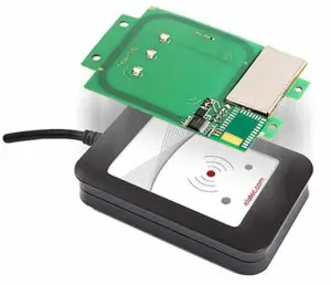
Introduction
The transponder reader TWN4 MultiTech 2 M LF is a device for reading and writing RFID transponders with a frequency of 125kHz. There are different versions of TWN4 devices available, which cover a large range of transponder types.
Getting Started
Cable Connection
In order to start operating a TWN4 transponder reader, it simply has to be connected to a host.
Power Up
Once a TWN4 reader is connected to the host, it detects the type of communications cable (USB or RS232), with which it is connected to the host.Additionally, the RS232 is sending a version string via RS232 to the host.
Enumeration (USB Only)
This is only applicable for the USB version: Once the device has been powered up, it is waiting for completion of the enumeration by the USB host. As long as the device is not enumerated, it is entering a minimum power consumption mode, where both LEDs are turned off.
Initialization
After powering up and enumeration (in USB mode), the device is turning on the built-in transponder reader logic. The green LED is turned on permanently. Some transponder reader modules need some kind of initialization, which is performed in this step. After successful initialization, the device sounds a short sequence, which consists of a lower tone followed by a higher tone.
Normal Operation
As soon as the device has completed the initialization, it is entering normal operation. During normal operation the device is searching for a transponder continuously.
Detection of a Transponder
If a transponder is detected by the reader, following actions are performed
- Send the ID to the host. By default, the USB device sends by emulating keystrokes of a keyboard. A RS232 device sends the ASCII code of an ID.
- Sound a beep
- Turn off the green LED
- Blink the red LED for two seconds
- Turn on the green LED
Within the two seconds timeout, where the red LED is blinking, the transponder, which just has been recognized will not be accepted again. This prevents the reader from sending identical IDs more than one time to the host.If during the two seconds timeout of the red LED a different transponder is detected, the complete sequence restarts immediately.
Suspend Mode (USB Only)
The USB version of the transponder reader supports the USB suspend mode. If the USB host is signaling suspend via the USB bus, the transponder reader is turning off most of its power consuming peripherals. During this operation mode, no detection of transponders is possible and all LEDs are turned off.Once the host is resuming to normal operation mode, this is also signaled via the USB bus. Therefore, the transponder reader will resume to normal operation, too.
List of Antennas
Compliance statements
FCC
(RF module)
Compliance statement:
This device complies with Part 15 of the FCC Rules. Operation is subject to the following two conditions:(1) this device may not cause harmful interference, and(2) this device must accept any interference received, including interference that may cause undesired operation.
Modification of equipment:
The instruction manual of the host shall include the following statement:Changes or modifications made to this equipment not expressly approved by the party responsible for compliance may void the FCC authorization to operate this equipment
Information to the user:
(The instruction manual of the host shall include the following statement) A compliance statement as applicable, e.g., for devices subject to part 15 of CFR 47 as specified in §15.19(a)(3), that the product complies with the rules; and the identification, by name, address and telephone number or Internet contact information, of the responsible party, as defined in §2.909. The responsible party for Supplier’s Declaration of Conformity must be located within the United States.
Host devices
FCC notes for a host subject to verification or SDoC:
For a host device assembled with the certified module and subject to 47 CFR Part 15 verification of class A digital devices, the following statements have to be included in the user manual and the host device has to be labelled as noted below. If the host device is subject to other authorization procedures or parts the appropriate requirements of these authorization procedures or parts apply.
Important note:
OEM integrator is still responsible for the FCC compliance requirements of the end product, which integrates this module. Appropriate measurements (e.g. 15B compliance) and if applicable additional equipment authorization of the host device to be addressed by the integrator/ manufacturer
The end device must be labeled with:
Contains FCC ID: WP5TWN4F13Contains IC: 7948A-TWN4F13HVIN: EL20203
Example for SDoC:
Supplier’s Declaration of Conformity
Uniquie Identifier: (e.g., Trade Name, Model Number)
Party issuing Supplier’s Declaration of ConformityABC CooperationStreet AddressCity, StatePostal CodeCountry Telephone number or internet contact information
Responsible Party – U.S. Contact InformationStreet, AddressCity, StatePostal CodeUnited StatesTelephone number or internet contact information
FCC Compliance Statement(for products subject to Part 15)This device complies with Part 15 of FCC Rules. Operation is subject to the following two conditions: (1) This device may not cause harmful interference, and (29 this device must accept any interference received, including interference that may cause undesired operation.
The compliance information statement shall be included in the user’smanual or as a separate sheet. In cases where the manual is provided only in a form other than paper, such as on a computer disk or over the Internet, the information required by this section may be included in the manual in that alternative form, provided the user can reasonably be expected to have the capability to access information in that form. The information may be provided electronically as permitted in §2.935.
NOTE: The Commission does not have a required SDoC format. This is an example only and is provided to illustrate the type of information that may be supplied with the product at the time of marketing or importation for meeting the FCC SDoC requirement.
For class B devices:FCC §15.105 (b):Note: This equipment has been tested and found to comply with the limits for a Class B digital device, pursuant to part 15 of the FCC Rules. These limits are designed to provide reasonable protection against harmful interference in a residential installation. This equipment generates, uses and can radiate radio frequency energy and, if not installed and used in accordance with the instructions, may cause harmful interference to radio communications. However, there is no guarantee that interference will not occur in a particular installation. If this equipment does cause harmful interference to radio or television reception, which can be determined by turning the equipment off and on, the user is encouraged to try to correct the interference by one or more of the following measures:
- Reorient or relocate the receiving antenna.
- Increase the separation between the equipment and receiver.
- Connect the equipment into an outlet on a circuit different from that to which the Receiver is connected.
- Consult the dealer or an experienced radio/TV technician for help.
For class A devices:
FCC §15.105 (b):NOTE: This equipment has been tested and found to comply with the limits for a Class A digital device, pursuant to part 15 of the FCC Rules. These limits are designed to provide reasonable protection against harmful interference when the equipment is operated in a commercial environment. This equipment generates, uses, and can radiate radio frequency energy and, if not installed and used in accordance with the instruction manual, may cause harmful interference to radio communications. Operation of this equipment in a residential area is likely to cause harmful interference in which case the user will be required to correct the interference at his own expense.
CANADA:
This device complies with Industry Canada’s license-exempt RSSs. Operation is subject to the following two conditions:(1) This device may not cause interference; and(2) This device must accept any interference, including interference that may cause undesired operation of the device.
Special accessories:
Where special accessories such as shielded cables and/or special connectors are required to comply with the emission limits, the instruction manual shall include appropriate instructions on the first page of the text describing the installation of the device.
Simultaneous transmission:
When the host product supports simultaneous-transmission operations the host manufacturer needs to check if there are additional RF exposure filing requirements due to the simultaneous transmissions. When additional application filing for RF exposure compliance demonstration is not required (e. g. the RF module in combination with all simultaneously operating transmitters complies with the RF exposure simultaneous transmission SAR test exclusion requirements), the host manufacturer may do his own evaluation without any filing, using reasonable engineering judgment and testing for confirming compliance with out-of-band, restricted band, and spurious emission requirements in the simultaneous-transmission operating modes. If additional filing is required please contact the person at ELATEC GmbH responsible for certification of the RF module.
Service Address
In case of any technical questions, please contact:
Elatec GmbHZeppelinstr. 182178 Puchheim Germany
Phone: +49 (0) 89 5529961 0Fax: +49 (0) 89 5529961 129Email: [email protected]
 report this ad
[xyz-ips snippet=”download-snippet”]