ELATION Pixel Driver 1000IP
GENERAL INFORMATION
INTRODUCTION
Please read and understand the instructions in this manual carefully and thoroughly before attempting to operate this device. These instructions contain important safety and use information.
UNPACKING
Every device has been thoroughly tested and has been shipped in perfect operating condition. Carefully check the shipping carton for damage that may have occurred during shipping. If the carton is damaged, carefully inspect the device for damage, and be sure all accessories necessary to install and operate the device have arrived intact. In the event damage has been found or parts are missing, please contact our customer support team for further instructions. Please do not return this device to your dealer without first contacting customer support. Please do not discard the shipping carton in the trash. Please recycle whenever possible.
BOX CONTENTS
- Twist-Lock Power Cable (x1)
- 4-pin Data Cable (x1)
- Rack Mount Brackets w/ Hardware (x2)
- IP65 Power Cable Connector Kit (x1)
CUSTOMER SUPPORT
Contact ELATION Service for any product related service and support needs. Also visit forums.elationlighting.com with questions, comments or suggestions.
ELATION SERVICE USA – Monday – Friday 8:00am to 4:30pm PST 323-582-3322 | Fax 323-832-9142 | [email protected]
ELATION SERVICE EUROPE – Monday – Friday 08:30 to 17:00 CET +31 45 546 85 63 | Fax +31 45 546 85 96 | [email protected] REPLACEMENT PARTS please visit parts.elationlighting.com
![]() IMPORTANT NOTICE!THERE ARE NO USER SERVICEABLE PARTS INSIDE THIS UNIT.DO NOT ATTEMPT ANY REPAIRS YOURSELF; DOING SO WILL VOID YOUR MANUFACTURER’S WARRANTY. DAMAGES RESULTING FROM MODIFICATIONS TO THIS FIXTURE AND/OR THE DISREGARD OF SAFETY INSTRUCTIONS AND GUIDELINES IN THIS MANUAL VOID THE MANUFACTURER’S WARRANTY AND ARE NOT SUBJECT TO ANY WARRANTY CLAIMS AND/OR REPAIRS.
IMPORTANT NOTICE!THERE ARE NO USER SERVICEABLE PARTS INSIDE THIS UNIT.DO NOT ATTEMPT ANY REPAIRS YOURSELF; DOING SO WILL VOID YOUR MANUFACTURER’S WARRANTY. DAMAGES RESULTING FROM MODIFICATIONS TO THIS FIXTURE AND/OR THE DISREGARD OF SAFETY INSTRUCTIONS AND GUIDELINES IN THIS MANUAL VOID THE MANUFACTURER’S WARRANTY AND ARE NOT SUBJECT TO ANY WARRANTY CLAIMS AND/OR REPAIRS.
LIMITED WARRANTY (USA ONLY)
A. Elation Professional hereby warrants, to the original purchaser, Elation Professional products to be free of manufacturing defects in material and workmanship for a period of two years (730 days), and Elation Professional product rechargeable batteries to be free of manufacturing defects in material and workmanship for a period of six months (180 days), from the original date of purchase. This warranty excludes discharge lamps and all product accessories. This warranty shall be valid only if the product is purchased within the United States of America, including possessions and territories. It is the owner’s responsibility to establish the date and place of purchase by acceptable evidence, at the time service is sought.B. For warranty service, send the product only to the Elation Professional factory. All shipping charges must be pre-paid. If the requested repairs or service (including parts replacement) are within the terms of this warranty, Elation Professional will pay return shipping charges only to a designated point within the United States. If any product is sent, it must be shipped in its original package and packaging material. No accessories should be shipped with the product. If any accessories are shipped with the product, Elation Professional shall have no liability what so ever for loss and/or or damage to any such accessories, nor for the safe return thereof.C. This warranty is void if the product serial number and/or labels are altered or removed; if the product is modified in any manner which Elation Professional concludes, after inspection, affects the reliability of the product; if the product has been repaired or serviced by anyone other than the Elation Professional factory unless prior written authorization was issued to purchaser by Elation Professional; if the product is damaged because not properly maintained as set forth in the product instructions, guidelines and/or user manual.D. This is not a service contract, and this warranty does not include any maintenance, cleaning or periodic check-up. During the periods as specified above, Elation Professional will replace defective parts at its expense, and will absorb all expenses for warranty service and repair labor by reason of defects in material or workmanship. The sole responsibility of Elation Professional under this warranty shall be limited to the repair of the product, or replacement thereof, including parts, at the sole discretion of Elation Professional. All products covered by this warranty were manufactured after January 1, 1990, and bare identifying marks to that effect.E. Elation Professional reserves the right to make changes in design and/or performance improvements upon its products without any obligation to include these changes in any products theretofore manufactured.F. No warranty, whether expressed or implied, is given or made with respect to any accessory supplied with the products described above. Except to the extent prohibited by applicable law, all implied warranties made by Elation Professional in connection with this product, including warranties of merchantability or fitness, are limited in duration to the warranty periods set forth above. And no warranties, whether expressed or implied, including warranties of merchantability or fitness, shall apply to this product after said periods have expired. The consumer’s and/or dealer’s sole remedy shall be such repair or replacement as is expressly provided above; and under no circumstances shall Elation Professional be liable for any loss and/or damage, direct and/ or consequential, arising out of the use of, and/or the inability to use, this product.G. This warranty is the only written warranty applicable to Elation Professional products and supersedes all prior warranties and written descriptions of warranty terms and conditions heretofore published.
WARRANTY RETURNS
All returned service items whether under warranty or not, must be freight pre-paid and accompany a return authorization (R.A.) number. The R.A. number must be clearly written on the outside of the return package. A brief description of the problem as well as the R.A. number must also be written down on a piece of paper and included in the shipping container. If the unit is under warranty, you must provide a copy of your proof of purchase invoice. Items returned without a R.A. number clearly marked on the outside of the package will be refused and returned at customer’s expense. You may obtain a R.A. number by contacting customer support.
SAFETY GUIDELINES
This fixture is a sophisticated piece of electronic equipment. To guarantee smooth operation, it is important to follow all instructions and guidelines in this manual. Elation Professional is not responsible for injury and/or damages resulting from the misuse of this fixture due to the disregard of the information printed in this manual. Only qualified and/or certified personnel should perform installation of this fixture and only the original rigging parts included with this fixture should be used for installation. Any modifications to the fixture and/or the included mounting hardware will void the original manufacturer’s warranty and increase the risk of damage and/or personal injury.
 |
PROTECTION CLASS 1 – FIXTURE MUST BE PROPERLY GROUNDED. |
 |
THERE ARE NO USER SERVICEABLE PARTS INSIDE THIS UNIT. DO NOT ATTEMPT ANY REPAIRS YOURSELF. DOING SO WILL VOID YOUR MANUFACTURER’S WARRANTY. DAMAGES RESULTING FROM MODIFICATIONS TO THIS DEVICE AND/OR THE DISREGARD OF SAFETY INSTRUCTIONS AND GUIDELINES IN THIS MANUAL VOID THE MANUFACTURER’S WARRANTY AND ARE NOT SUBJECT TO ANY WARRANTY CLAIMS AND/OR REPAIRS. |
|
DO NOT PLUG THIS UNIT INTO A DIMMER PACKDO NOT REMOVE THE COVER UNDER ANY CON.DITIONS NEVER OPERATE THIS UNIT WITH THE CASING REMOVED.UNPLUG FROM POWER DURING LONG PERIODS OF NON-USE.DISCONNECT POWER BEFORE PERFORMING MAINTENANCE. |
| IP65 | FIXTURE IS COMPLETELY DUST TIGHT AND PROTECTED AGAINST WATER PROJECTED BY A NOZZLE FROM ANY DIRECTION |
For Your Own Personal Safety, Please Read and Understand This Manual Completely Before You Attempt To Install Or Operate This Unit!
- Be sure to save the packing carton in the unlikely event the device may have to be returned for service.
- Be sure that the local power outlet matches the required voltage for the device.
- Do not open up the device under any conditions. There are no user serviceable parts inside.
- Disconnect the device’s main power when left unused for long periods of time.
- Never connect this device to a dimmer pack.
- Do not attempt to operate this device if it has been damaged in any way.
- Never operate this device with the cover removed.
- Do not attempt to operate this device if the power cord has been frayed or broken. Do not attempt to remove or break off the ground prong from the electrical cord. This prong is used to reduce the risk of electrical shock and fire in case of an internal short.
- Disconnect from main power before making any type of connection.
- Never block the ventilation holes. Always be sure to mount this device in an area that will allow proper ventilation. Allow about 6″ (15cm) between this device and a wall.
- Always mount this unit in a safe and stable matter.
- Please route your power cord out of the way of foot traffic. Power cords should be routed so they are not likely to be walked on, or pinched by items placed upon or against them.
- Keep flammable materials away from this fixture!
- IP65 Rating: Fixture is dust-tight, and protected against water projected by a nozzle from any direction. FIXTURE IS NOT PROTECTED AGAINST IMMERSION IN LIQUID OF ANY KIND!
- The device should be serviced by qualified service personnel when:A. The power-supply cord or the plug has been damaged.B. Objects have fallen on, or liquid has been spilled into, the device.C. The device has been immersed in liquid or exposed to powerful water jets or sprays.D. The appliance does not appear to operate normally or exhibits a marked change in performance.
OVERVIEW
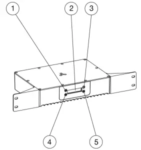
- Mode Button
- Display Screen
- Up Button
- Setup Button
- Down Button
- Underside Mounting Point
- Topside Mounting Point
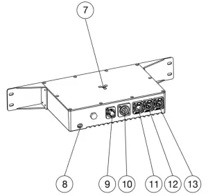
- Safety Cable Attachment
- Power In
- Power Out
- LED Out
- Net Data In
- Net Data Out
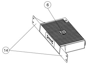
- Rack Mount Brackets (x2)
INSTALLATION
FLAMMABLE MATERIAL WARNING!Keep drive a minimum of 5.0 feet (1.5m) away from flammable material and/or pyrotechnics.
ELECTRICAL CONNECTIONSA qualified electrician should be used for all electrical connections and/or installations.
DO NOT INSTALL THE DEVICE IF YOU ARE NOT QUALIFIED TO DO SO!The driver MUST be installed following all local, national, and country commercial electrical and construction codes and regulations.Before installing or mounting any device, a professional equipment installer MUST be consulted to determine whether the mounting structure or surface is properly certified to safely support the combined weight of the device and any relevant accessories.The device should be installed in areas outside walking paths, seating areas, or away from areas where unauthorized personnel might be able to reach the device by hand.
INSTALLATION
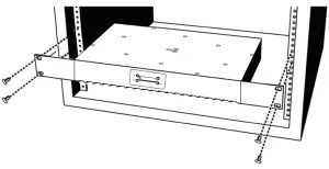
RACK MOUNTING
This device can be rack mounted using the removable mounting brackets located on each side of the device. Make sure to use mounting hardware that fits the mounting holes on the device as well as the rack itself. Use all four (4) points on the mounting brackets to ensure that the device is mounted securely. Please see the illustration below for reference.
CLAMP MOUNTING
This device features a mounting clamp attachment point in the middle of both the top face and the bottom face, as well as a built-in safety cable attachment point in the corner of the device near the Power In port (see the illustration below). When mounting the fixture to a truss or any other suspended or overhead installation, be sure to secure an appropriately rated clamp (not included) to the clamp attachment point and attach a separate SAFETY CABLE of the appropriate safety rating to the safety cable rigging point.
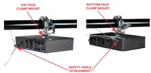
ALWAYS ATTACH A SAFETY CABLE WHENEVER INSTALLING THIS FIXTURE IN A SUSPENDED ENVIRONMENT TO ENSURE THAT THE FIXTURE WILL NOT FALL IF THE CLAMP FAILS.
RIGGING
Overhead rigging requires extensive experience, including but not limited to: calculating working load limits, understanding the installation material being used, and periodic safety inspection of all installation material and the fixture itself. If you lack these qualifications, do not attempt to perform the installation yourself. Improper installation can result in bodily injury.
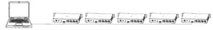
MULTIPLE DRIVERS
Up to five (5) Pixel Driver 1000IP devices may be daisy-chained directly together and linked to a single controller. See the image below for reference.Do NOT daisy-chain more than five (5) devices directly together.
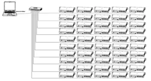
 If more than five (5) devices are required, a one-gigabit ethernet switch may be used to expand the size of the network. However, even in this case, no more than ten (10) branches from the ethernet switch are allowable, with each branch containing up to five (5) daisy-chained devices. This permits a maximum of fifty (50) devices to be linked to a single controller, as shown in the image below.Do NOT exceed this number of devices!
ALLOWABLE CABLE LENGTHS
|
CONTROLLER TO DEVICE |
59 ft (18 m) |
|
DEVICE TO DEVICE |
32 ft (10 m) |
| TOTAL LENGTH |
98 ft (30 m) |
DRIVER OUTPUT LIMITATIONS
There is a limitation to how many pixels can be controlled by each driver unit, which in turn determines the maximum number of lighting fixtures that can be controlled by a single output or driver.
| MODEL |
TOTAL PIXELS |
TOTAL CONTROL CHAN. | KLING-NETMAX PIXELS PER DRIVER = 1000 | |
| MAX FIXTURESperDRIVER UNIT |
MAX PIXELSperDRIVER UNIT |
|||
|
Pixel Bar 30IP |
30 | 90 | 33 |
990 |
|
Pixel Bar 60IP |
60 | 180 | 16 | 960 |
| Pixel Bar 120IP | 120 | 360 | 8 |
960 |
|
MODEL |
TOTAL PIXELS | TOTAL CONTROL CHAN. | ARTNET / sACNMAX PIXELS PER DRIVER = 170 | |
| MAX FIXTURESperDRIVER UNIT |
MAX PIXELSperDRIVER UNIT |
|||
|
Pixel Bar 30IP |
30 | 90 | 5 |
150 |
|
Pixel Bar 60IP |
60 | 180 | 2 | 120 |
| Pixel Bar 120IP | 120 | 360 | 1 |
120 |
The values listed in the table above for number of fixtures per driver unit are representative of the maximum number of Pixel Bar IP fixtures that can be connected if the Pixel Bar IP fixtures used are all of the same model type, with individual pixel control.
For example, if you connect only Pixel Bar 30IPs to the driver, and operate the driver in Kling-Net mode, you can connect up to 33 units of that model type to each driver. This is defined by the fact that each driver can handle a maximum of 1000 pixels, and each Pixel Bar 30IP fixture is made up of 30 pixels. Therefore, you have 33 Pixel Bar 30IP units x 30 pixels per unit, which gives a total of 990 pixels in use. This is as close as we can get to the 1000-pixel maximum capacity without exceeding that limit.
It is possible to mix and match Pixel Bar IP model types that are attached to a single driver port. In this case, the important thing to keep in mind is the maximum number of pixels per driver. As long as this value is not exceeded, any combination of Pixel Bar 30IPs, Pixel Bar 60IPs, and Pixel Bar 120IPs may be used.
RGB PIXEL CONTROL MODES
This feature gives the user the ability to adjust the RGB pixel control mode of the device. Individual pixels may be controlled independently for finer control over the resolution of the device’s lighting display. Alternately, multiple individual pixels may be grouped together under a common set of control channels in order to reduce the number of required control channels. This also reduces the effective pixel count for each fixture, thereby allowing an increased number of fixtures to be operated off of the same driver port (see the Driver Output Limitations section). The downside to this is the reduced resolution of the lighting display.
In each pixel control mode, the first number denotes the number of control groups that LEDs will be divided into, while the second number denotes the number of individual LEDs that will make up each control group. Each control group will always occupy 3 DMX channels (for Red, Green, and Blue control). This means that within each control group, all LEDs will be controlled by the same set of 3 DMX channels.
For example, when operating a Pixel Bar 30IP, selecting 15×2 mode means that the fixture’s LEDs will be divided into 15 RGB control groups, with each group containing 2 LEDs. See the illustration below: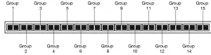
In this mode, a total of 45 DMX channels are used: 3 DMX channels (for Red, Green, Blue) per group multiplied by 15 groups.
If there are not enough unused DMX channels available to accommodate this set-up, one possible solution is to select a pixel control mode that will decrease the number of control groups. For instance, selecting 10×3 mode will result in the LED display being divided into 10 RGB control groups each containing 3 LEDs. Therefore, the number of DMX channels required drops to 30: 10 control groups multiplied by 3 DMX channels (for Red, Green, and Blue) per group. See the illustration below: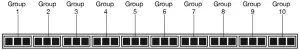
Available pixel control modes for each Pixel Bar IP model are shown on the next page.
Available pixel control modess:
|
Pixel Bar 30IP |
Pixel Bar 60IP | Pixel Bar 120IP |
| 30×1 | 60×1 |
120×1 |
|
15×2 |
30×2 | 60×2 |
| 10×3 | 20×3 |
40×3 |
|
6×5 |
15×4 | 30×4 |
| 5×6 | 12×5 |
24×5 |
|
3×10 |
10×6 | 20×6 |
| 2×15 | 6×10 |
15×8 |
|
5×12 |
12×10 | |
| 4×15 |
10×12 |
|
|
3×20 |
8×15 | |
| 2×30 |
6×20 |
|
|
5×24 |
||
|
4×30 |
||
| 3×40 | ||
|
2×60 |
CONTROL PANEL
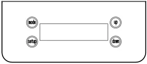
The device includes an easy to navigate system menu control panel display where all necessary settings and adjustments are made (see image below).– The MODE button is used to cycle through main menu options, or to return to the previous menu.– The SETUP button is used to select an option in either the main menu or the sub-menu of any main menu item, and to cycle through the sub-menu options. – The UP and DOWN buttons are used to adjust the values of the sub-menu options.
| MANUAL CONTROL | Red Dimmer | Manual Control Red: x x x | Red color intensity | ||
| Green Dimmer | Manual Control Green: x x x | Green color intensity | |||
| Blue Dimmer | Manual Control Blue: x x x | Blue color intensity | |||
| KLINGNET MODE | Pixel Bar Setup | Klingnet Pixel Bar x x x IP | Select model of Pixel Bar that will be controlled by the driver | ||
| Klingnet LED Bulb | TBD* | ||||
| Klingnet LED Tape | TBD* | ||||
| Klingnet x x x IP Number x x | Select the number of Pixel Bar units that the driver will control | ||||
| Klingnet LED Bulb Numbe x x x | TBD* | ||||
| Klingnet LED Tape 170 Numbe x x |
TBD* |
||||
| Klingnet x x X x x RGB Pixels | see RGB Pixel Control section | ||||
| ARTNET MODE | IP Address Set | Artnet x x x : x x x : x x x : x x x | Set IP address of the driver output | ||
| DMX Universe Set | Artnet U: x x x x x | Set the DMX universe of the driver output | |||
| Pixel Bar Setup | Artnet Pixel Bar x x x IP | Select model of Pixel Bar that will be controlled by the driver | |||
| Artnet LED Bulb | TBD* | ||||
| Artnet LED Tape | TBD* | ||||
| Artnet x x x IP Numbe x x x | Select the number of Pixel Bar units that the driver will control | ||||
| Artnet LED Bulb Numbe x x x | TBD* | ||||
| AR TNET MODE
(cont’d from prev page) |
Pixel Bar Setup (cont’d from prev page) | Artnet LED Tape 170 Numbe x x |
TBD* |
||
| Artnet x x X x x RGB Pixels | see RGB Pixel Control section | ||||
| sACN MODE CONTRO L | DMX Universe Output Set | sACN U: x x x x x | set DMX universe of the output | ||
| Pixel Bar Setup | sACN Pixel Bar x x x IP | Select model of Pixel Bar that will be controlled by the driver | |||
| sACN LED Bulb | TBD* | ||||
| sACN LED Tape | TBD* | ||||
| sACN x x x IP Number x x | Select the number of Pixel Bar units that the driver will control | ||||
| sACN LED Bulb Numbe x x x | TBD* | ||||
| sACN LED Tape 170 Numbe x x |
TBD* |
||||
| sACN x x X x x RGB Pixels | see RGB Pixel Control section | ||||
| PROGRAMS | Program Play Set | Programs Program x x | Select program | the | built-in |
| Programs Speed x x | Select program speed | ||||
| Programs Fade x x | Set fade time speed | ||||
| Programs Phase Time x x | Set phase time | ||||
| Pixel Bar Setup | Programs Pixel Bar x x x IP | Select model of Pixel Bar that will be controlled by the driver | |||
| Programs LED Bulb | TBD* | ||||
| Programs LED Tape | TBD* | ||||
| BUILT IN PROGRAM
MODE (cont’d from prev page) |
Pixel Bar Setup (cont’d from prev page) | Programs x x x IP Number x x | Select the number of Pixel Bar units that the driver will control | ||
| Programs LED Bulb Numbe x x x | TBD* | ||||
| Programs LED Tape 170 Numbe x x | TBD* | ||||
| KLINGNET & ARTNET CONTROL MODE | Klingnet Enable or Disable Set | Klingnet & Artnet Klingnet: Enable/Disable | Enable or disable klingnet control | ||
| Klingnet Pixel Bar Setup | Klingnet Setup Pixel Bar x x x IP | Select model of Pixel Bar that will be controlled by the driver | |||
| Klingnet Setup LED Bulb | TBD* | ||||
| Klingnet Setup LED Tape | TBD* | ||||
| Klingnet Setup x x x IP Number x x | Select the number of Pixel Bar units that the driver will control | ||||
| Klingnet Setup LED Bulb Numbe x x x | TBD* | ||||
| Klingnet Setup LED Tape 170 Numbe x x | TBD* | ||||
| Artnet IP Address Set | Artnet Setup x x x : x x x : x x x : x x x | Set IP address of the output | |||
| Artnet Universe Set | Artnet Setup U: x x x x x | Set DMX universe of the output | |||
| SETUP OPTIONS |
LCD Backlight On/Off |
Setup Options: BLGT On | LED backlight always on | ||
| Setup Options: BLGT Off | LED backlight turns off
after 20s of inactivity |
||||
| Display | Setup Options: Display: STD | Normal digital display orientation | |||
| Setup Options: Display: REV | Inverted digital display orientation | ||||
| System Reset | Setup Options: SysReset | Restore unit to factory settings | |||
|
OUTPUT TYPE |
Output Type Set |
Drive: Pixel Bar | Pixel Bar IP series | ||
| Drive: LED Bulb | LED Bulb |
*LED Bulb and LED Tape settings are intended for use with upcoming Elation Products.
DIMENSIONAL DRAWINGS
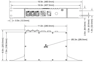
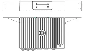 Dimensions not to scale.
SPECIFICATIONS
CONTROL / CONNECTIONSManual RGB Mode Internal Programs Art-NET | sACN | Kling-NET Protocols 2 RJ45 Ethernet Ports 1 4pin Power/Data Output
SIZE / WEIGHTLength: 18.9″ (480mm) * With Rack Ears Width: 8.0″ (203.5mm) Height: 2.5″ (64mm) Weight: 8 lbs. (3.6kg)
ELECTRICALAC Input 100-240V – 50/60HZ, 2.2A DC Output 24V, 8.4A IP65 rated locking power IN/Out 200W Max Power Consumption -4°F to 113°F (-20°C to 45°C)
APPROVALSCE | cETLus
Specifications and documentation subject to change without notice.
FCC STATEMENTThis device complies with Part 15 of the FCC Rules. Operation is subject to the following two conditions: (1) this device may not cause harmful interference, and (2) this device must accept any interference received, including interference that may cause undesired operation.
FCC RADIO FREQUENCY INTERFERENCE WARNINGS & INSTRUCTIONSThis product has been tested and found to comply with the limits as per Part 15 of the FCC Rules. These limits are designed to provide reasonable protection against harmful interference in a residential installation. This device uses and can radiate radio frequency energy and, if not installed and used in accordance with the included instructions, may cause harmful interference to radio communications. However, there is no guarantee that interference will not occur in a particular installation. If this device does cause harmful interference to radio or television reception, which can be determined by turning the device off and on, the user is encouraged to try to correct the interference by one or more of the following methods:
- Reorient or relocate the device.
- Increase the separation between the device and the receiver.
- Connect the device to an electrical outlet on a circuit different from which the radio receiver is connected.
- Consult the dealer or an experienced radio/TV technician for help.
Europe Energy Saving NoticeEnergy Saving Matters (EuP 2009/125/EC)Saving electric energy is a key to help protecting the environment. Please turn off all electrical products when they are not in use. To avoid power consumption in idle mode, disconnect all electrical equipment from power when not in use. Thank you
©2020 ELATION PROFESSIONAL all rights reserved. Information, specifications, diagrams, images, and instructions herein are subject to change without notice. ELATION PROFESSIONAL logo and identifying product names and numbers herein are trademarks of ELATION PROFESSIONAL. Copyright protection claimed includes all forms and matters of copyrightable materials and information now allowed by statutory or judicial law or hereinafter granted. Product names used in this document may be trademarks or registered trademarks of their respective companies and are hereby acknowledged. All non-ELATION brands and product names are trademarks or registered trademarks of their respective companies.
ELATION PROFESSIONAL and all affiliated companies hereby disclaim any and all liabilities for property, equipment, building, and electrical damages, injuries to any persons, and direct or indirect economic loss associated with the use or reliance of any information contained within this document, and/or as a result of the improper, unsafe, insufficient and negligent assembly, installation, rigging, and operation of this product.
Elation Professional USA | 6122 S. Eastern Ave. | Los Angeles, CA. 90040 323-582-3322 | 323-832-9142 fax | www.elationlighting.com | [email protected]Elation Professional B.V. | Junostraat 2 | 6468 EW Kerkrade, The Netherlands +31 45 546 85 66 | +31 45 546 85 96 fax | www.elationlighting.eu | [email protected]Elation Professional Mexico | AV Santa Ana 30 | Parque Industrial Lerma, Lerma, Mexico 52000 +52 (728) 282-7070
DOCUMENT VERSION
 Due to additional product features and/or enhancements, an updated version of this document may be available online. Please scan the QR Code with your mobile device or visit www.elationlighting.com for the latest revision/update of this manual, before installation and/or programming.
|
Date |
Document Version | Software Version | DMX Channel Mode |
Notes |
|
10/30/20 |
1.0 | 1.0 | N/A | Initial Release |
| 04/14/21 | 1.5 | 1.0 | N/A |

References
[xyz-ips snippet=”download-snippet”]