Elecro Evolution 2 Pool Heater
User Manual

INTRODUCTION
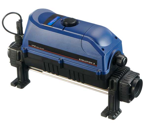
Thank you for purchasing an Evolution 2 electric swimming pool heater manufactured to the highest standards in England.
To ensure years of trouble-free service, please read and follow these instructions for proper installation, maintenance and use.
WARNING: Failure to install the unit correctly may result in the warranty being void.
Please retain this manual for future reference.
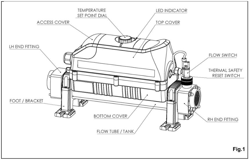
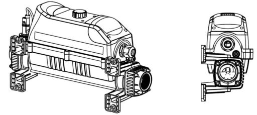
PRODUCT OVERVIEW
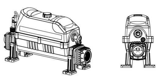
Dimensions :
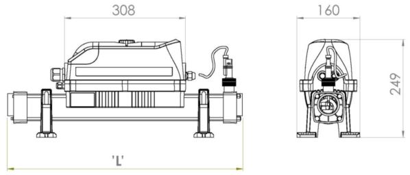
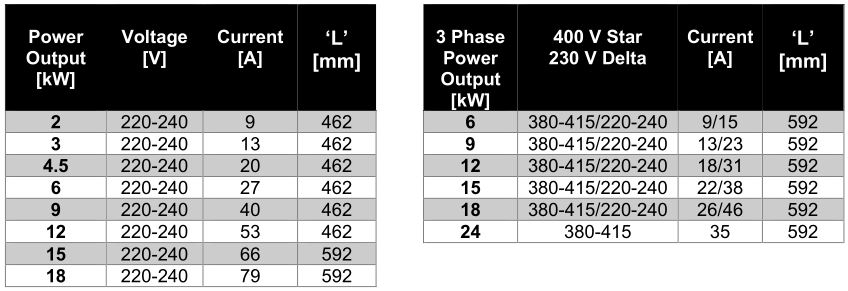
* for dimension ‘L’ – refer to section 2.5
GENERAL INSTALLATION INSTRUCTION
Mounting instruction
The heater should be either installed horizontally or vertically allowing enough space for the pipe connections and wiring. It should be firmly secured using screws to a firm base or wall.
WARNINGS: If the heater is placed against a combustible material a fireproof barrier must be placed between the unit and the wall, this must cover a minimum of 15cm around the outside of the heater. The unit must not be covered to allow adequate ventilation.
The heater must be installed within a dry, permanent weather-proof area. In any case where water or moisture enters the enclosure the warranty will be void.
Caution: If the heater is unused during the winter months, it must be drained to prevent frost damage. Water must not be allowed to freeze in the heater, as this will cause severe damage.
See Fig. 2 for mounting instructions when securing to the wall or floor.
FLOOR MOUNT
WALL MOUNT
Pipe work
The heater should be installed at a low point in the filtration system. It should be positioned downstream of (after) the filter and upstream of (before) any dosing or other water treatment plan (see Fig 3).
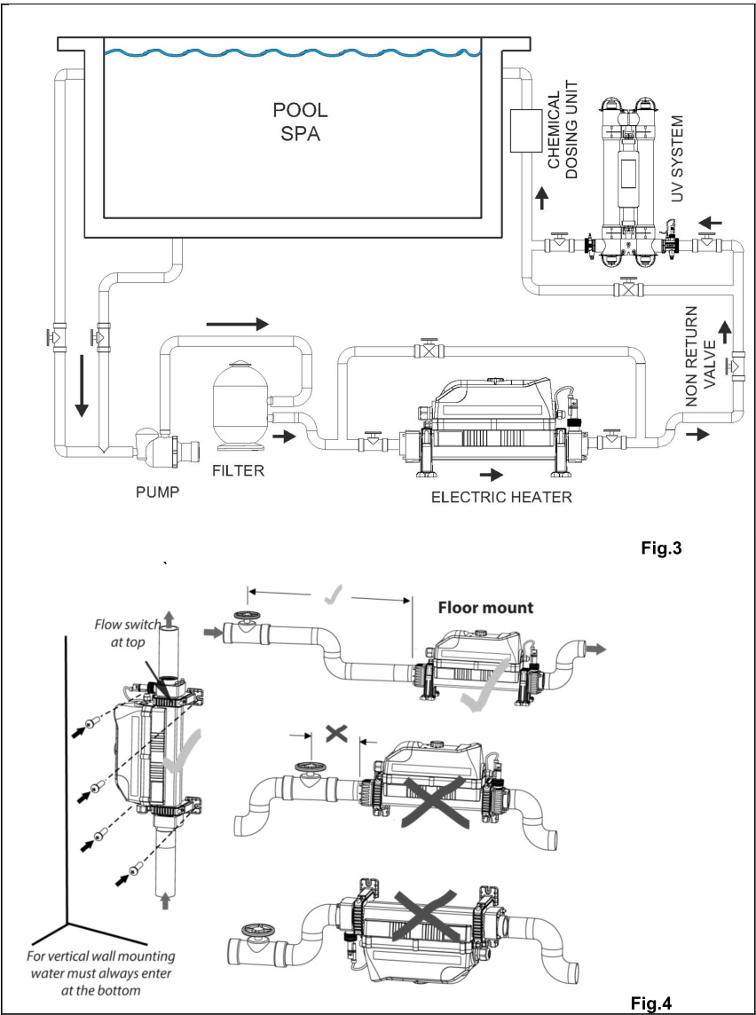
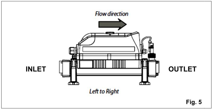
Flow direction
The heater can accept flow of water from only one end (see Fig. 5). If the flow direction is opposite to Fig. 5 the heater must be rotated by 180° so the flow switch is always where the water exits.
DO NOT REVERSE THE FLOW SWITCH
It is essential that the pipe work connecting to and from the heater has a minimum bore (internal diameter) of 32mm. To support correct air purging and to ensure the heater remains completely full of water during operation, the return pipe which carries the water back to the pool must incorporate a safety loop or ‘kick-up’ in the pipe as close as possible to the heater (see Fig 4).
NOTE: When coupling to a flexible pipe a safety loop can easily be formed by directing the pipe up and over an obstacle. Pipe clips should be used to securely fasten all hose connections.
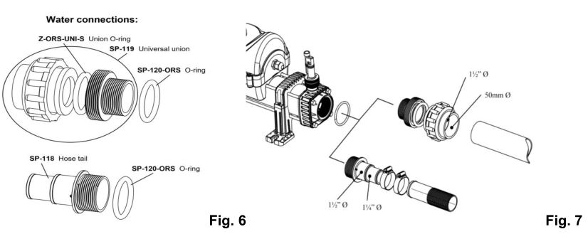
If rigid pipework is used
There is no need to use mastic or PTFE tape to connect unions or hosetails to the heater, use the O-ring supplied which should be slid over the threaded ends (see Fig. 6).
All factory unions are made from ABS plastic, when gluing connections to an ABS pipe an ABS cement must be used (see Fig. 7).
NOTE: Be sure to apply the glue evenly and to all surfaces that will be in contact to reduce the risk of leakage.
If flexible pipework is used
Connect the pipe to the non-threaded side of the hosetail and secure using two jubilee clips (See Fig. 7)
Note:
- The hosetail may need to be cut depending on the diameter of the pipe.
- Wrap PTFE tape or use silicone around the hosetail before connecting the pipe to reduce the risk of leakage.
- When using non-standard pipework, the first thing to note is that the smooth end of the pipe will not fit into anything other than another fitting of the same brand. You will have to cut it off. The hose tail will push fit in to the cut end of the pipe, but it will not be watertight. You can put two jubilee clips on it but because of the ridges in the pipe it will not squeeze down tight. It will need to be sealed with a bathroom type mastic sealant.
Electrical connection
WARNINGS:
- This device must be installed by a qualified Electrician following the instructions provided in this manual. The manufacturer will not be liable for any issues caused by poor or improper installation.
- Any alterations made to the unit (unless stated) will affect the warranty. This also applies if components are changed for non-standard components acquired anywhere other than direct from the manufacturer.
- Incorrect installation may result in serious damage to property/persons.
- The heater must be installed in accordance with the country/regional requirements and regulations and an Electrical Installation Certificate must be provided on completion of the installation.
- The power supply must be fitted with a 30mA RCD. If required, the Electrician may replace the cable entry gland supplied with a larger size to secure the cable powering the heater.
Minimum cable sectional area
This should be calculated at 5-amp/mm 2 for distances up to 20 metres (these sections are indicative and should be checked and adapted if necessary, for cable lengths over 20 metres).
Connections
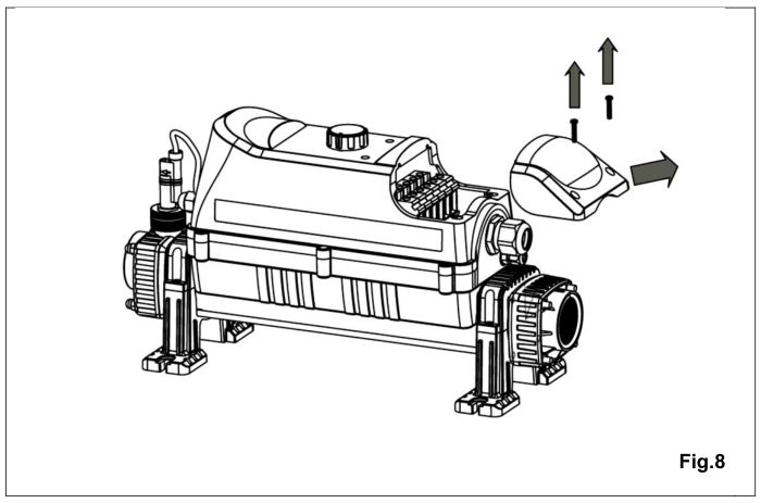
- To connect the power supply cable, remove access cover (see Fig. 8).
- Make sure that all connections to the terminal block are correct as per the label inside the heater and they are tight.
- Make sure not to expose the cable to anything which can cause damage to it i.e. sharp edges, hot surfaces, or crush hazards.
- The cable should be fixed to avoid any trip hazard.
Power requirements
Dedicated RCD safety circuit
- The heater is fitted with a high limit Safety Circuit which must be connected to a dedicated RCD and circuit breaker.
- The Safety Circuit is constantly monitoring the flow tube temperature. Air pockets, incrustation, debris build-up or faulty components can be a reason of a sudden temperature rise inside the flow tube. To protect heating elements and other components the Safety Circuit will trigger the RCD and shut down the power to the heater.
WARNING: The Safety Circuit must be connected. Failure to do so will void the warranty and might result in product failure.
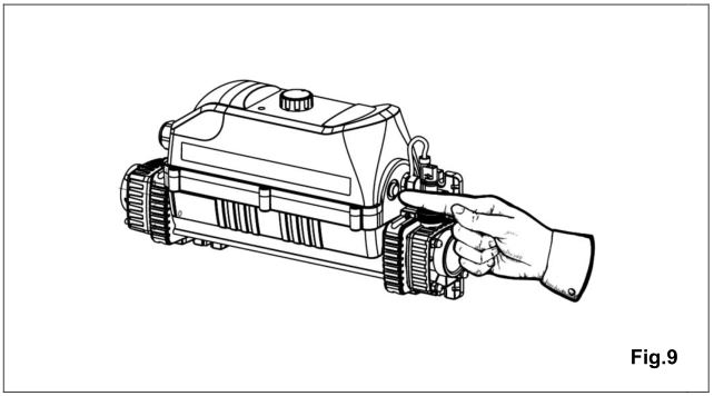
NOTE: The Safety Circuit is fitted with a TEST BUTTON which must be tested after completing installation of the heater to confirm it is operating correctly. When pressed, the RCD should instantly trip and cut the power to the unit (See Fig. 9).
OPERATING INSTRUCTIONS
Flow requirements
The flow rate of water into the heater must not exceed 17,000 litres per hour (17m 3 /hour/3,740 UK gallons per hour). A higher flow rate will require the installation of a bypass to prevent damage to the heater elements.
NOTE: The heater will not operate unless the following minimum flow rates are achieved:1,000 litres/hour (1m 3 /hour/220 UK gallons/hour) for 2 to 6 – kW heaters4,000 litres/hour (4m 3 /hour/880 UK gallons/hour) for 9 to 24 – kW heaters
Water quality
The water quality MUST be within the following limits:
- PH: 6.8 – 8.0
- Total Alkalinity (TA): 80 – 140 ppm (parts per million)
- Chloride Content MAX: 150 mg/litre
- Free Chlorine: 2.0 mg/litre
- Total Bromine: Max 4.5 mg/litre
- Total Dissolved Solids (TDS)/Calcium hardness: 200 – 1,000 ppm
Stainless Steel heaters are NOT suitable for use on saline (salt) water pools. ONLY heaters with titanium heating elements are suitable for use on saline (salt) water pools.
WARNING: Failure to meet the water quality limits will void the warranty.
Upon completion of the installation, run the water-circulating pump to purge the system and heater of air (i.e. remove any trapped air in the system and heater).
- Switch on the power supply to the heater. This will be indicated by the illuminated Amber light on the panel.
- Turn the thermostat to the desired temperature.
- The heater will only start heating (red light indicator illuminated) when the following criteria are met:
- Water circulating pump is ‘On’ delivering more than the minimum flow rate of water (see 3.1 flow requirement).
- The required water temperature point is set to a higher value than that of the water.
Useful advice:To reduce running costs and speed up the heating process, insulate the pool wherever possible. A floating solar cover is an essential minimum to retain heat.
Selector knob operation
To aid navigation through the controller options, the digital heater is fitted with a selector knob for easy and user-friendly navigation.
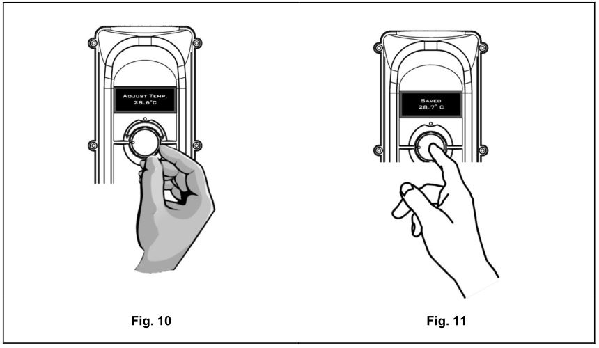
To adjust or select any option simply turn the knob clockwise or anti-clockwise (see Fig. 10).
To confirm selected option, press the knob button (OK). The display should show message ‘SAVED’ confirm the changes (see Fig. 11).
Choose your language
On initial power up, the display will illuminate and show a language message, (see Fig. 12). If the controller detects inactivity for 3 seconds, it will default the language to English.
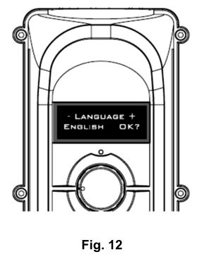
There are five languages to choose from English, French, Spanish, German and Russian.
To select a language, turn the knob clockwise or anti clockwise until the desired language is displayed. Press the knob button (OK) to accept the changes.
NOTE: To access language mode, press the knob button (during heating only). You can also access language mode by resetting power to the heater.
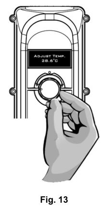
Set point
The setting can be changed (desired water temperature), any time by simply turning the knob clockwise or anti clockwise until the required temperature is shown on the display (see Fig.13). To confirm the changes, press the knob button (OK).
The display should show ‘SAVED’ message.
Heating mode
If the heater is receiving enough flow and the set point value is greater than the pool water temperature ‘HEATER DELAY’ will be shown on the display (see Fig. 14).
It will appear for two minutes before the device commences the heating process. The delay time is required to prevent a cycling effect due to air pockets trapped in the pipe work system or any water fluctuations. The combination of the delay time and flow switch sensor is ensuring that the device always receives enough flow and the heating element is fully submerged. This will extend the life expectancy of the components and the product.
After two minutes, the controller will switch on the heating output, RED LIGHT will come ON and the display will show current water temperature (see Fig. 15).
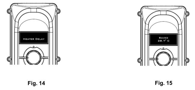
The heater will stay on until the set temperature point is reached. When reached the heater will maintain the pool temperature within 0.5°C differential.
Calibrate temperature
If for any reason the water temperature displayed by the controller is different to the water temperature in the pool, adjust this by pressing and holding the dial button for five seconds. The display will show calibrate and the actual temperature (see Fig. 16). Turn the dial clockwise to adjust it UP or anti clockwise to adjust it DOWN.
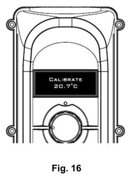
NOTE: The controller will allow maximum adjustments of ± 2°C. If the controller displays ‘No flow’ message, then entering the calibration mode will not be possible.
Useful advice:To reduce running costs and speed up the heating process, insulate the pool wherever possible. A floating solar cover is an essential minimum to retain heat.
TROUBLE SHOOTING
- Quick Function TestObserve the main electricity meter when the heater is on (i.e. red light ‘On’) and then observe it again when the heater is in the standby mode (i.e. amber light ‘On’). The test should show that the meter is recording more electricity being used by the heater when the red light is ‘On’. It is impossible for an electric heater to waste energy, if it is drawing power then that power will be turned into heat that will be transferred to the water.
- Accurate Function TestIf a more accurate test is required to confirm that your heater is delivering the specified heat output, two electricity meter readings will need to be taken from the property’s main electricity meter, at one hourly intervals (i.e. take one-meter reading and then a second reading exactly one hour later). By subtracting the first reading from the second reading the number of units (kilo Watts kW) consumed can be calculated. Note that your heater is also rated in kW hours.The pool pump and heater will need to be running continuously during the test (i.e. with the heater red light ‘On’. To avoid inaccurate results when performing this test, it is important to refrain from using other high current consuming appliances in the property, such as tumble dryers, showers, cookers etc. A large domestic pool pump of one horsepower will draw less than 1-kW in a one-hour period. The conclusion of the test should prove that for example a 6-kW heater and a half horsepower pump will draw between 6.3-kW to 6.5-kW in one hour.
- Heater will not switch from standby to on (Red light):In most cases this will be the result of one of the following points not being met:
- Possible Cause 1: The temperature point set has been achieved. To confirm the increase of the temperature set, turn the dial to a value greater than the current water temperature.
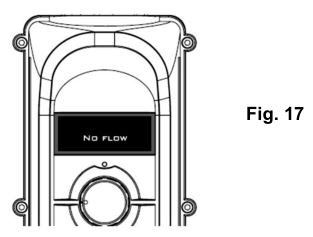
- Possible Cause 2: NO FLOW messageThis message is displayed (see Fig.17) only when the heater is not receiving enough flow. This could be due to the circulation pump being switched off. The pump is not powerful enough to meet the flow requirements (See 3.1 Flow requirements). The cartridge filter needs cleaning or replacing. The sand/glass media filter creates too high a back pressure and needs a backwash.

- Possible Cause 3: HEATER DELAY messagePlease refer to Page 9
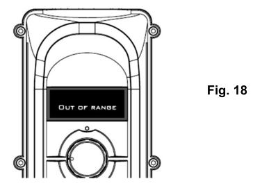
- Possible Cause 4: OUT OF RANGE messageThis error message will be shown (see Fig.18) in case of the temperature sensor failure or in case the temperature inside the flow tube is outside of the measurement range of the sensor (0 – 100°C). During the winter the time temperature could drop below 0°C.
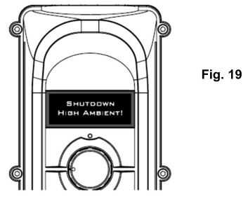
- Possible Cause 5: SHUTDOWN HIGH AMBIENT message (See Fig.19). The heater is fitted with intelligence sensors not only monitoring the water temperature but also the temperature within the electrical enclosure. To protect the components if the temperature inside the enclosure reaches 60°C, the controller will shut down and go to STAND BY mode. This could be due to the product being exposed to direct sunlight, operating in a very hot environment. As soon as the temperature drops down the heater will come back on to heating mode automatically.
- No display on the heater when it is switched ‘On’Possible Cause: Power failure external to the heaterRemedy: Check any fuses, RCD or other switch components installed in the supply cable.NOTE: The heater PCB control board is fitted with a fuse which should be inspected.
- The flow tube does not feel warm:Due to the high efficiency of your electric heater no warmth should be detectable from the flow tube of the heater.The most likely causes of the flow tube feeling warm are:Possible Cause 1: The heater has been positioned in direct sunlight.Possible Cause 2: An air pocket is trapped inside the heater particularly if the tank feels warmer at the highest point of the tank (as air rises).
- The water entering the pool does not feel much warmer:The temperature gain of the water after it has passed through the heater will be directly proportional to the volume of water being pumped in relationship to the power output of the heater.For example: A 6-kW heater, when connected to a 4,000 litre/hour pump will produce a lift in temperature of approximately 1.2°C (almost undetectable to the human hand), however, as the water being heated is re-circulated from a single body of water, the time required to heat it remains unaffected by the volume of the flow. A popular misconception is that slowing down the flow rate will speed up the heating process.
- Heater is tripping circuit breaker (MCB) after few minutes/ hours of operation:If the heater is faulty it will instantly trip the circuit breaker (MCB). The most likely causes of tripping the breaker after a period of time are:Possible Cause 1: Faulty circuit breaker.Possible Cause 2: Incorrect size of the circuit breaker.Possible Cause 3: Cross section of the cable is not sufficient.Possible Cause 4: Loose connection(s) of the power supply cable. Check both ends of the power supply cable (at the distribution box and at the heater terminal block).Remedy: Contact an Electrician to check installation and protection.
- Heater is tripping circuit breaker (MCB) or RCD instantly:Possible Cause 1: Short circuit caused by the wiring or faulty components.Possible Cause 2: Heating element is going to ground or is damaged.Possible Cause 3: Moisture inside the heater.Remedy: Send heater back to the manufacturer. Use return form on page 18 or download it from the Elecro website.
- Power supply cable is getting very hot:Possible Cause 1: Cross section of the power supply cable is not sufficient.Possible Cause 2: Loose connection(s) of the power supply cable. Check both ends of the power supply cable (at the distribution box and at the heater terminal block).Remedy: Contact an Electrician to check installation. Inspect for loose connections and upgrade the power supply cable to a bigger size if necessary.
MAINTENANCE
We recommend annual maintenance and cleaning of the heater to ensure proper operation.
WARNING: Before performing any maintenance on the unit isolate from the main power supply.
The heater should be drained, the flow tube and heating elements should be cleaned. Removing scale/sludge and any debris or blockages will extend life expectancy of the heating element(s) and avoid potential failures.
Check that electrical cable connections are properly tightened.
DISPOSAL OF ELECTRICAL AND ELECTRONIC EQUIPMENT
DO NOT dispose of this product as an unsorted municipal waste.
This symbol on the product or on the packaging indicates that this product should not be treated as household waste. Instead it should be handed over to the applicable collection point for the recycling of electrical and electronic equipment.
![]()
By ensuring this product is disposed of correctly you will help prevent potential negative consequences for the environment and human health, which could otherwise be caused by inappropriate waste handling of this product. The recycling of materials will help to conserve natural resources.
For more information please contact your local Civic Office, household waste disposal service or the retailer where the product was purchased.
WARRANTY
This product is guaranteed from the date of purchase against faulty workmanship and materials for:
– two years within Europe– one year outside Europe
- The manufacturer will replace or repair, at its discretion, any faulty units or components returned to the Company for inspection.
- Proof of purchase may be required.
- The manufacturer will not be liable in cases of incorrect installation of the heater, inappropriate use or neglect of the heater.
- Any damages occurred due to shipping must be reported within 48 hours of receipt of the product. Any claims after this time will be considered as misuse or abuse of the product and will not be covered by the warranty.
- Any glass parts, seals and water connections are considered as consumables and are not covered by the warranty.
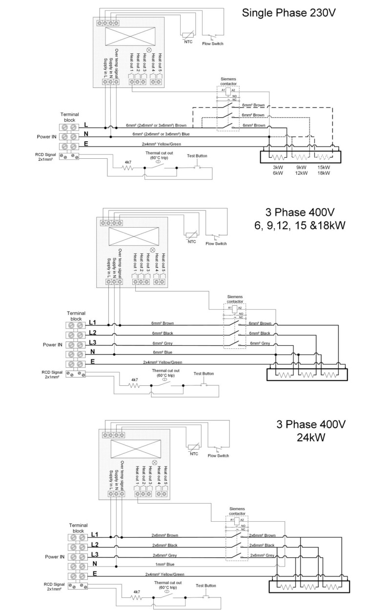
DEDICATED RCD WIRING DIAGRAM FOR CORRECT OPERATION OF THE EVOLUTION 2 HEATER
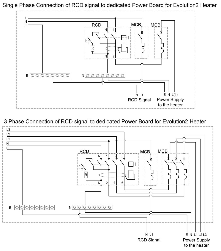
WIRING DIAGRAMS:
Elecro Engineering LtdRepairs DepartmentUnit 11 Gunnels Wood ParkGunnels Wood RoadStevenageHertfordshire SG1 2BHUnited Kingdom
![]()
11 Gunnels Wood Park, Stevenage, Herts SG1 2BH[email protected]www.elecro.co.uk+44 (0) 1438 749474© Copyright V01.2019
Elecro Evolution 2 Pool Heater User Manual – Elecro Evolution 2 Pool Heater User Manual –
[xyz-ips snippet=”download-snippet”]