![]()
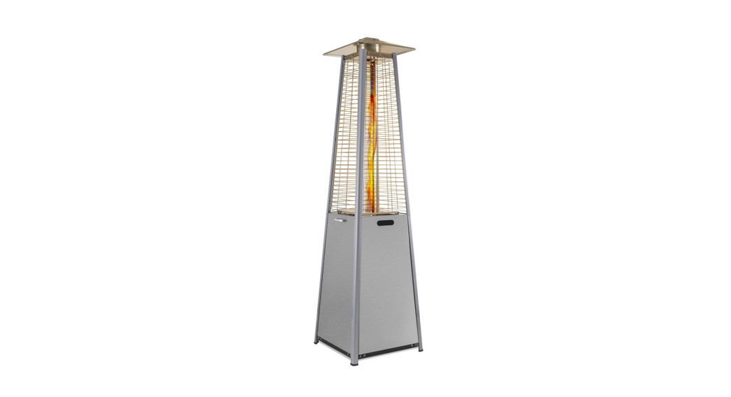
USER MANUAL 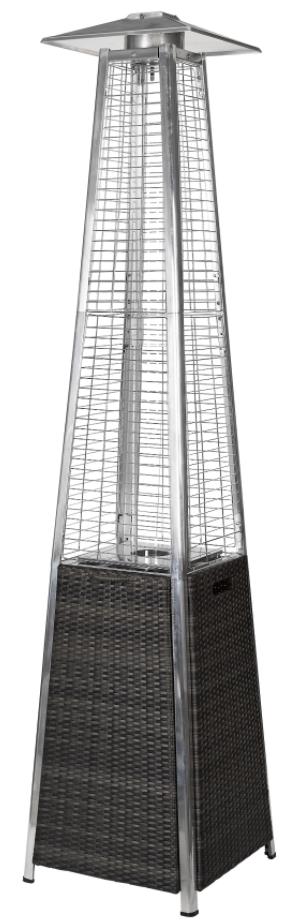 GAS PATIO HEATER
| EQODHFTBR | BROWN WICKER/RATTAN |
| EQODHFLGR | GREY WICKER /RATTAN |
WARNING: FOR OUTDOOR USE ONLY OR IN WELL VENTILATED AREAS PLEASE KEEP THE MANUAL FOR FUTURE REFERENCE
IMPORTANT SAFETY INFORMATION
Please read this user manual before using this heater and keep it safe for future reference.
- Read the following instructions carefully and be sure your patio heater is properly installed, assembled, and cared for. Retain the instructions for future reference.
- Failure to follow these instructions may result in serious bodily injury and/or property damage.
- WARNING – Risk of Suffocation! Gas heaters must be used outdoors and must not be used in enclosed areas such as sheds or marquees!
- Read the instruction manual before using the appliance.
- WARNING: Accessible parts may be very hot. Keep young children away.
- This appliance must be kept away from flammable materials during use.
- Do not move the appliance during use.
- The appliance should be secured to the ground when in use.
- Turn off the gas supply at the gas cylinder after use.
- Do not modify this appliance.
- If you have any questions concerning assembly or operation, consult the retailer or Bottled Gas Company.
- Always place the appliance and cylinder on flat level ground.
- Turn off the gas cylinder if a gas leak is suspected.
- Parts sealed by the manufacturer must not be altered by the user. No modifications should be made to any part of this heater and repairs and maintenance should only be carried out by a registered Gas Safe service engineer.
- Use only regulator and hose approved for LP Gas at the correct pressures and gas type.
- The regulator should comply with the standard EN16129 and current regulations in the country where it is installed, which may be found at your nearest retailer of gas items.
- Refer to the technical data. It is strictly prohibited to use adjustable pressure.
- The life expectancy of the regulator is estimated as 10 years. It is recommended that the regulator is changed within 10 years of the date of manufacture or the national conditions require it.
- The type of replaceable hose should be compliant with EN16436-1.
- The hose used must conform to the relevant standard for the country of use. The length of the hose must be 0.7 meters (minimum) and 1.5 meters (maximum). A worn or damaged hose must be replaced. Ensure that the hose is not obstructed or kinked. It is recommended that the hose is changed within 1 year of the date of manufacture or as the national conditions require.
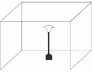
For use outdoors or in well-ventilated areas.
- A well-ventilated area must have a minimum of 25% of the surface area open.
- The surface area is the sum of the surface of the wall.
- The use of this appliance in enclosed areas can be dangerous and is PROHIBITED.
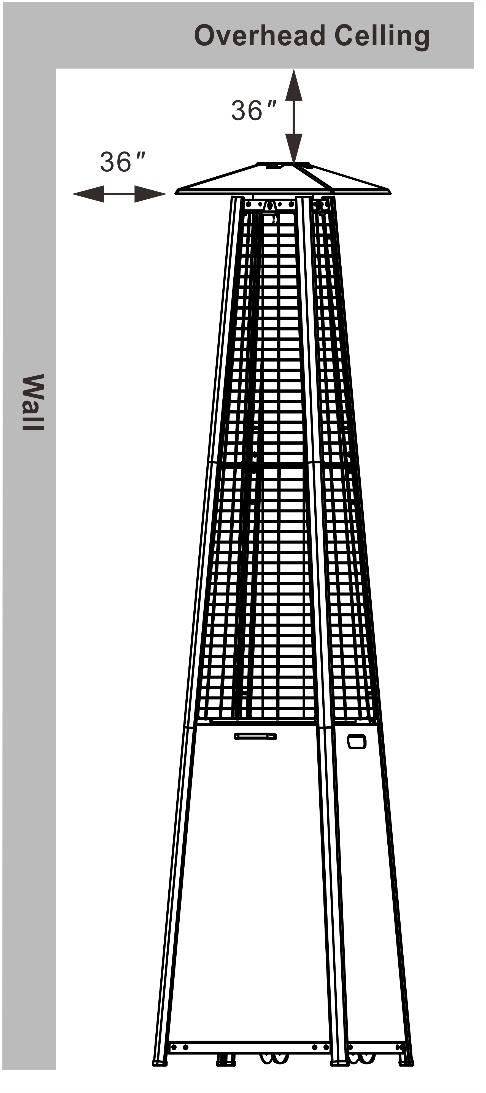
- Children and adults should be aware of the high operating temperatures of areas above the post when operating this heater. Children should be carefully supervised when in the vicinity of the heater.NEVER hang anything, including clothes or any other flammable items, on this heater.DO NOT operate this heater unless it is fully assembled. Respect the minimum clearances from combustible materials.
GENERAL INFORMATION FOR SUCCESSFUL ASSEMBLY
Please read the assembly instructions carefully and follow the safety precautions. Allow sufficient time for assembly. Before starting assembly, clear an area measuring approximately two to three square meters. Remove the item from the packaging and layout all of the parts and any necessary tools so that they are within easy reach.Only tighten all of the screw connections firmly when you have finished assembly or are instructed to within the manual. Otherwise, this can result in unwanted tension and instability.
PRODUCT OVERVIEW AND PART LIST

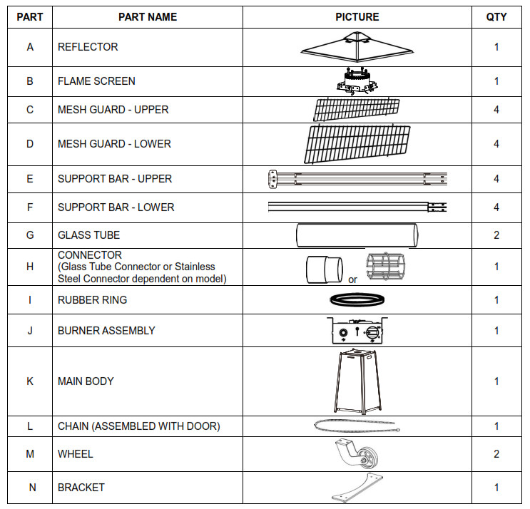
Note: Some of the fittings may be provided pre-attached to the unit.
PATIO HEATER ASSEMBLY
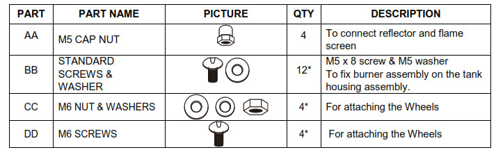
Required Tools: Philip Screwdriver / Adjustable Spanners / Wrenches Leak Detection Solution: One-part detergent and three parts water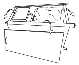 Before assembly, ensure all packing material and any transit protection is removed. Remove the door from the main body, and remove all the parts packed within it.
STEP 1(Optional): Connect the BRACKET (N) and WHEELS (M) to the base of the Main Body using the M6 SCREWS, WASHERS and NUTS (CC and DD)
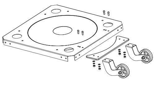
STEP 2: Keep the burner with the ignition side up. Fix the BURNER ASSEMBLY (J) to MAIN BODY (K) using 4 M5 SCREWS and WASHERS (BB).
STEP 3: Unscrew the M5 SCREWS and WASHERS (BB) preassembled in SUPPORT BAR – LOWER (F).Connect the UPPER SUPPORT BAR (E) to the LOWER SUPPORT BAR (F) and fix them together using the SCREWS and WASHERS. Repeat this step for all 4 SUPPORT BARS. 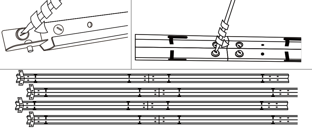
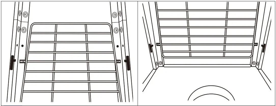
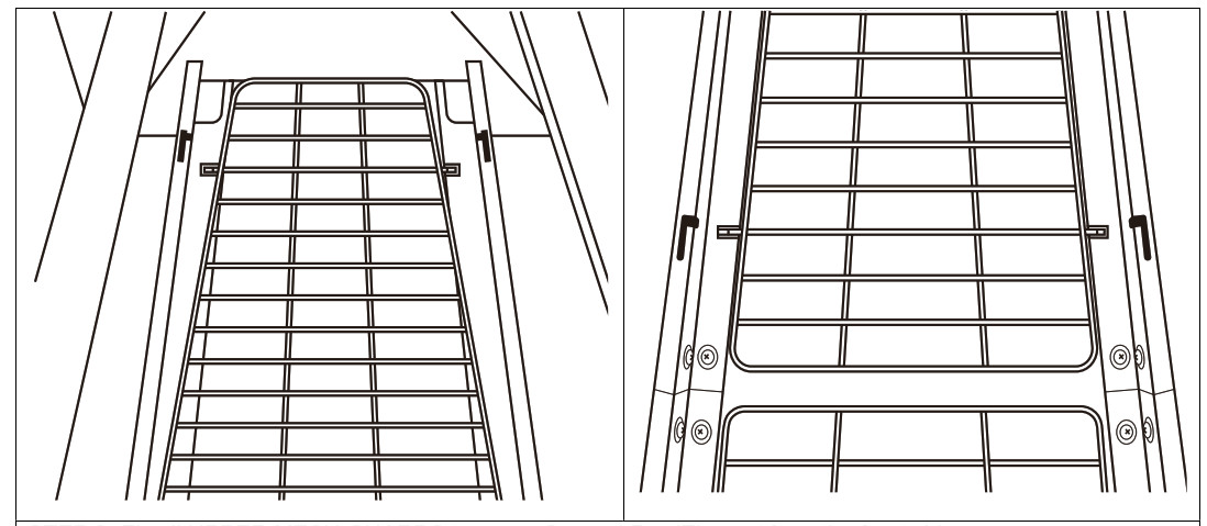
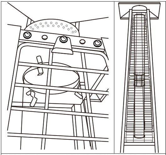
STEP 4: Attach the FLAME SCREEN (B) to the top of assembled SUPPORT BAR and fix using two M5 SCREWS and WASHERS (BB) (See Figure 1, 2). Repeat this step to connect the FLAME SCREEN (B) to the other 3 assembled SUPPORT BARS. (See Figure 3, 4)
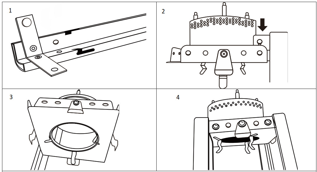
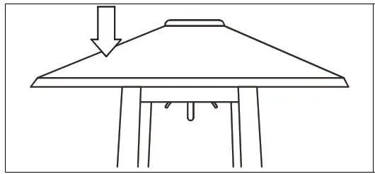
STEP 5: Place REFLECTOR (A) on the FLAME SCREEN (B) and secure using four M5 CAP NUTS (AA).
STEP 6: Unscrew the eight M5 Screws and Washers preassembled on top of the MAIN BODY (K).Place the bottom of the SUPPORT BARS on the top of the MAIN BODY. Make sure to match the top of the MAIN BODY with the SUPPORT BAR. Match the threaded hole and fix each connection with 2pcs M5 SCREWS and WASHERS (BB)
STEP 7: Insert the 4 projecting ends of each LOWER MESH GUARD (D) into the seat slots of SUPPORT BAR (F) as shown in the picture. Fix all the LOWER MESH GUARDS (D) except the front side.
Guard Fastening PlateSTEP 8: Unscrew the four GUARD FASTENING PLATES from the sides of FLAME SCREEN (B)
STEP 9: Fix all UPPER MESH GUARDS to the upper Support Bar (E) apart from the front side.
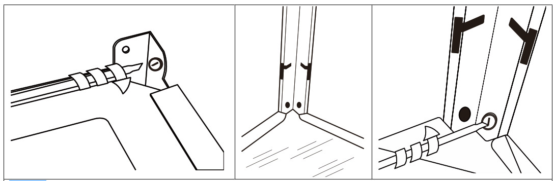
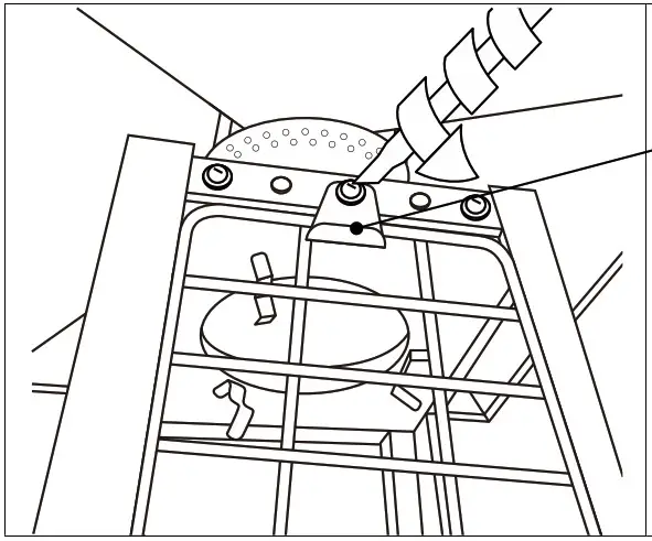
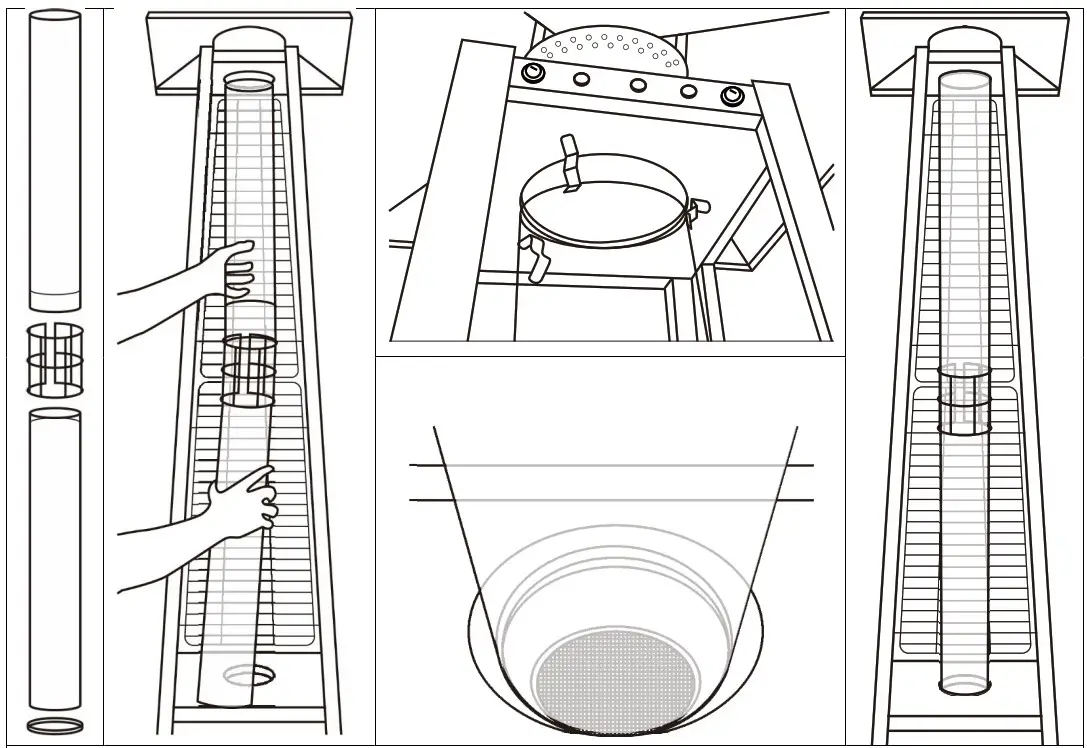
STEP 10: Put the RUBBER RING (I) around the burner hole. Use the CONNECTOR (H) to join the two GLASS TUBES (G). Hold the whole glass tube assembly carefully. Insert the top end into the bottom hole of the FLAME SCREEN and slide through it as far as possible. Keep the whole glass tube assembly vertically and sit it on theRUBBER RING (I).NOTE: GLASS TUBES ARE FRAGILE, HANDLE WITH GLASS TUBES CAREFULLY AND SLOWLY!
STEP 11: Assemble LOWER MESH GUARD (D) and UPPER MESH GUARD (C) to the front of the unit. Fix the Guard Fastening Plates removed in step 8 to secure the UPPER MESH GUARDS (C) in position.
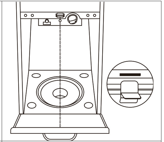
STEP 12: Insert the base of the door into the bottom lots. Attach the CHAIN (L) to the hook on the BURNER ASSEMBLY (J) and close the door.
OPERATING INSTRUCTIONS
BEFORE FIRST USE AND AFTER EVERY GAS CYLINDER CHANGE, THE GAS DELIVERY SYSTEM MUST BE PURGED OF AIR BEFORE IGNITING! TO DO THIS, TURN THE CONTROL DIAL ANTI-CLOCKWISE TO THE PILOT SETTING. PRESS THE DIAL-IN AND HOLD FOR 1 MINUTE BEFORE ATTEMPTING IGNITION.
BATTERY REPLACEMENTRemove the ignition cap from the BURNER ASSEMBLY (J) by turning the cap counterclockwise. Install 1 AAA battery. The negative end of the battery goes in first, then replace the ignition cap by turning the cap clockwise.
TO LIGHT THE PILOT

- Check all connections prior to each use.
- Turn on the gas supply at the source.
- Press and turn the control dial anti-clockwise to the PILOT marking.
- Hold the dial down and press the IGNITION button repeatedly until the pilot flame is lit, then continue to hold the dial down for 10 seconds until the pilot remains lit after releasing the dial.
- If the pilot fails to ignite, press and turn the dial clockwise to OFF before repeating the lighting steps.
TO LIGHT THE PATIO HEATER
- The pilot should be lit and the dial set to PILOT.
- Hold the dial down and turn anti-clockwise to the LOW position.
- When the mesh glows, turn the dial clockwise to select the desired heat output.Note: The burner may be noisy when initially turned on. To eliminate excessive noise from the burner, turn the control dial to the pilot position. Then turn the dial to the level of heat desired.
RE-LIGHTING
- Turn the Dial to the OFF position.
- Wait at least 5 minutes, to let the gas dissipate, before attempting to re-light the pilot.
- Repeat the “Lighting” steps.
TO EXTINGUISH
- Hold the dial down and turn clockwise to the OFF position
- Turn off the valve on the gas cylinder or the regulator after use.
- Disconnect the gas bottle and allow this appliance to cool before moving the appliance.Note: After use, some discoloration of the emitter screen is normal. Turn off the regulator after use and allow the appliance to cool before moving.
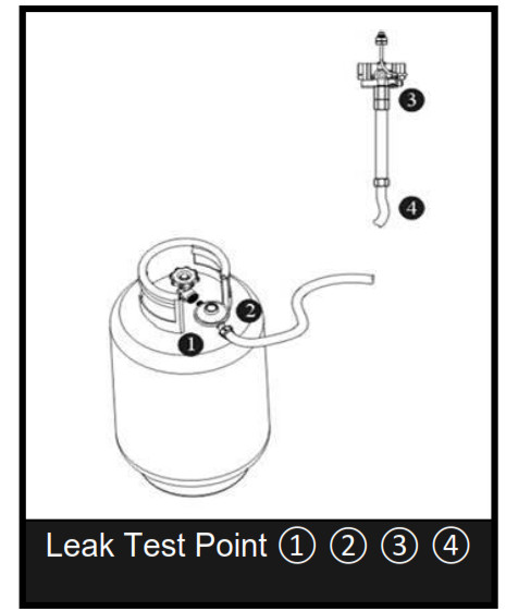
LEAK TESTINGNEVER USE A NAKED FLAME TO CHECK FOR LEAKS.NEVER LEAK TEST WHILE SMOKING.The gas connections on this appliance are leak tested at the factory prior to shipment.This appliance needs to be periodically checked for leaks and an immediate check is required if the smell of gas is detected.
- Make a soap solution using 1 part of liquid dish-washing soap to 3 parts water. The soap solution can be applied with a soap bottle, brush, or rag to the leak-tested points shown in the figure above.
- The valve of the gas cylinder should be in the OFF position. Once the soapy solution is applied to the gas connections, the valve of the gas cylinder needs to be turned to the ON position.
- Soap bubbles will begin to form in the soapy solution if a leak is present.
- In case of a leak, turn off the gas supply. Tighten any leaking fittings, then turn the gas supply on and recheck.

GAS REQUIREMENTS
- The regulator and hose assembly used must conform to local safety requirements.
- Never use a gas cylinder with a damaged body, valve, collar, or foot ring. A dented or rusty gas tank may be hazardous and should be checked by a gas supplier.
- Never connect this appliance to an unregulated gas source.
- When the appliance is not in use, turn the gas cylinder OFF, before disconnecting it.
- Always perform a leak test on gas connections whenever a cylinder is connected. If bubbles form in the leak test solution, do not use it. Never use a flame to test for leaks.
CONNECTING TO A GAS CYLINDER
- Use a 9 kg gas cylinder. Please refer to your gas supplier for a suitable gas cylinder.
- Refer to your gas supplier for instructions on the use of your gas cylinder.
- Only change gas cylinders outdoors or in a well-ventilated area away from naked flames and any other source of ignition.
- The gas cylinder must always be used in an upright position.
- Close the heater control dial by turning fully clockwise.
- Close the gas cylinder tap and then attach the regulator onto the gas cylinder.
- Tighten all connections firmly and with a spanner where appropriate. The cylinder should be located on the cylinder base.
- Check for leaks at all joints using soapy water. If a leak is found, tighten the joint and then re-test.
MAINTENANCE
To enjoy years of outstanding performance from your heater, make sure you perform the following maintenance activities on a regular basis:
- Keep exterior surfaces clean.
- Use warm soapy water for cleaning. Never use flammable or corrosive cleaning agents.
- While washing your unit, be sure to keep the area around the burner and pilot assembly dry at all times. Ifthe gas control is exposed to water in any way, DO NOT try to use it. It must be replaced.
- Airflow must be unobstructed. Keep controls, burner, and circulation air passageways clean. Signs of possible blockage include:
- Gas odor with extreme yellow tipping of flame.
- The heater does NOT reach the desired temperature.
- The heater’s glow is excessively uneven.
- The heater makes popping noises.
- Spiders and insects can nest in burner or orifices. This dangerous condition can damage the heater and render it unsafe for use. Clean burner holes by using a heavy-duty pipe cleaner. Compressed air may help clear away smaller particles.
- Carbon deposits may create a fire hazard. If any carbon deposits develop, clean the dome and burner with warm soapy water.Note: In environments with high salt content (such as near the sea), corrosion occurs more quickly than normal. Frequently check the corroded areas and repair them.
SERVICING
- Please consult your supplier for servicing this appliance and replacement of its parts. The servicing of the appliance shall be carried out only by authorized personnel.
- Do not use unauthorized parts or components for this appliance, only use original equipment replacement parts and components. The use of unauthorized parts or components will void the warranty and can create an unsafe condition.
STORAGEThere is no limitation on the storage of the appliance indoors provided that the cylinder is disconnected and removed from the appliance.Between uses or before storage:
- Turn the control dial OFF
- Turn the gas cylinder OFF
- Disconnect the gas bottle.
Store the heater upright in an area sheltered from direct contact with inclement weather (such as rain, sleet, hail, snow, dust, and debris). If desired, cover to protect exterior surfaces and to prevent build-up in air passages.Note: Wait until the heater is cool before covering.
TROUBLESHOOTING
| PROBLEM | CONDITION | FIX |
| The pilot won’t light | The cylinder valve is closed | Open valve |
| Blockage in orifice or pilot tube | Clean or replace orifice or pilot tube | |
| Air in the gas line | Open gas line and bleed it (pressing control dial-in) for not more than 1- 2 minutes or until you smell gas | |
| Low gas pressure | Gas cylinder low or empty | |
| Ignition fails | Change the Battery | |
| The pilot won’t stay lit | Dirt build-up around the pilot | Clean dirt from around the pilot |
| The connection between the gas valve and pilot assembly is loose | Tighten the connection and perform a leak test | |
| Bad thermocouple | Replace the thermocouple | |
| Burner won’t light | Gas pressure is low | Replace the gas cylinder |
| Blockage in the orifice | Clear the blockage | |
| The control dial is not in the “HIGH” position | Turn the control dial to the “HIGH” position | |
| The burner flame is low Note: Do not operate heater below 5°C(40 F) | Gas pressure is low | Replace the gas cylinder |
| The tank is almost empty. | Replace the gas cylinder | |
| The supply hose is bent or kinked | Straighten hose and perform a leak test on the hose | |
| The control dial is full ” ON” | Turn the control dial to “OFF”, let it cool to room temperature and check burner and orifices for blockage | |
| Emitter glows uneven Note: Bottom 2.5cm of emitter does notnormally glow | Gas pressure is low | Replace the gas cylinder |
| The base is not on a level surface | Place heater on a level surface | |
| Heater not level | Level the heater | |
| Carbon build-up | Dirt or film onthe reflector and/or emitter | Clean the reflector and emitter |
| Thick black smoke | Blockage in burner | Turn the control dial to the OFF position, let it cool to room temperature and remove the blockage, and clean the burner inside and outside. |
TECHNICAL SPECIFICATIONS
 Model: EQODHFTBR, EQODHFLGRHeat input ∑Qn(Hs)=11.2kWConsumption: 815g/hPIN: 0063CO7365
| Country Code | CH-ES-FR- GB-GR- IE-IT- PT | BE-CY-CZ-DK-EE-FI-GR-IT-LTLV-MT-NL- NO-SE-SISK-BG-R0- TR | AT-CH-DE | PL | CZ-FR-GB- GR-IE-PT | AT-CHDE-NL |
| Gas Category | 13+(28-30/37) | 138/13(30) | I3BIP(50) | 136/P(37) | I3P(37) | I3P(50) |
| Type of Gas | Butane /Propane | Propane | Butane/ Pmrioxpuarnee / | Butane/ 110’rioxpuarnee / | Butane/ Propane / | Propane |
| Gas pressure | 28-30mbar | 37mbar | 30mbar | 50mbar | 37mbar | 37mbar |
| Injector Marking | 2. | 2. | 1. | 2. | 2. | 2. |
WarningRead the instructions before using this appliance.The appliance must be installed in accordance with instructions and local regulations.The use of this appliance in enclosed areas can be dangerous and is PROHIBITED.For use outdoors or in amply ventilated areas.An amply ventilated area must have a minimum of 25% of the surface area open.The surface area is the sum of the surface of the wall.
electriQ UK SUPPORTwww.electriQ.co.uk/supportCall: 0330 390 3061 or complete the online form Office hours: 9 AM – 5 PM Monday to Fridaywww.electriQ.co.ukUnit J6, Lowfields Business ParkLowfields Way, EllandWest Yorkshire, HX5 9DA
References
[xyz-ips snippet=”download-snippet”]