electro-harmonix POG2 Polyphonic Octave Generator Pedal User Manual
Congratulations on your purchase of the POG 2! The POG 2 is a Polyphonic Octave Generator that draws its heritage from the now legendary POG, originally released in 2005 to worldwide acclaim. The POG 2 can simultaneously generate multiple octaves from your input signal. Whether you play single notes, arpeggios or full chords, the POG 2 will perfectly track every note you play. With the POG 2, you can mix together your original “dry signal” with four different octaves: one octave above the original note, two octaves above the original note, one octave below your original note and two octaves below the original note. Additionally you can detune the two upper octaves, slow the attack on all voices including the dry signal and process the overall tone through a low pass resonant filter with adjustable filter cutoff and selectable Q. The POG 2 is fully programmable allowing you to store and load presets for performance and recording.
WARNING: Use only the 9.6 VDC 200mA adapter the POG 2 comes supplied with. Do not use any other adapters. Using other adapters, even those made by Electro-Harmonix, could cause harm to the unit, the adapter or you. The POG 2 does not use batteries.
CONTROLS
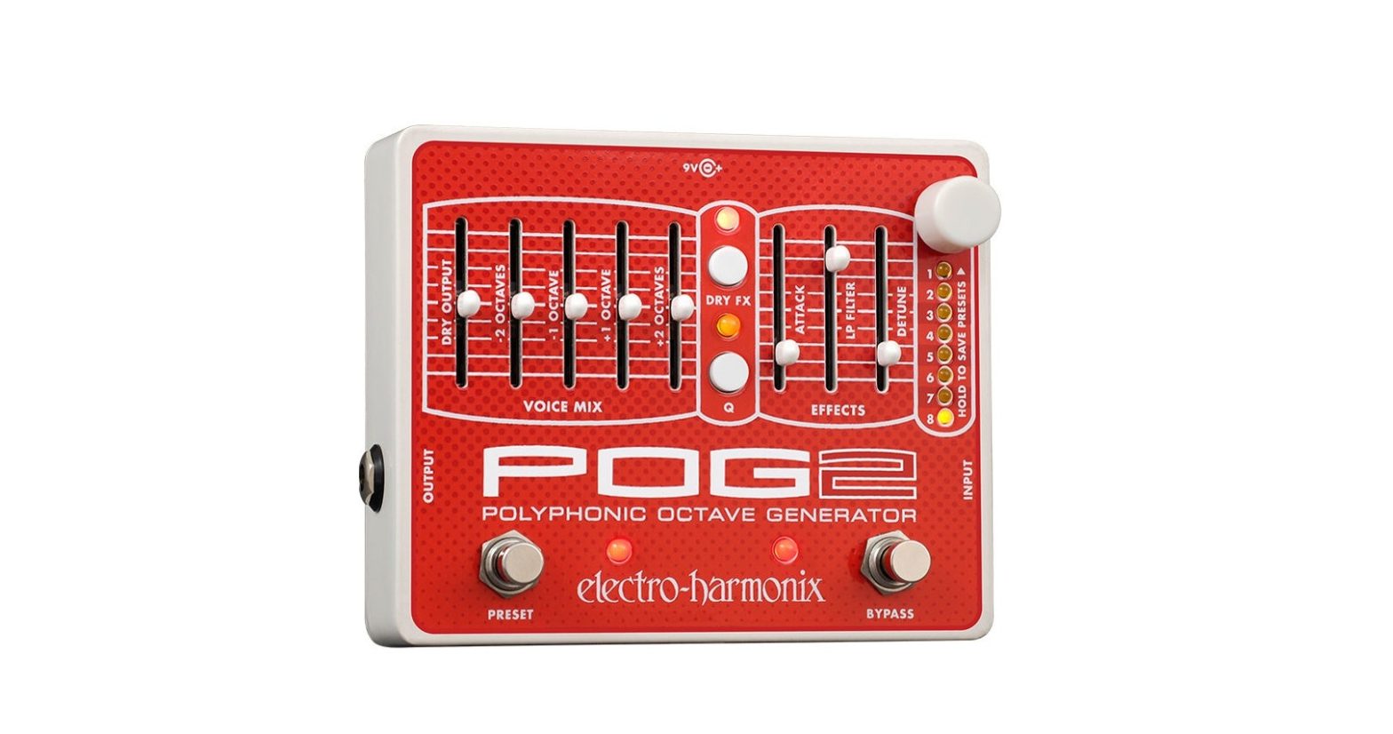
DRY OUTPUT Slider
Controls the output volume of your original DRY signal before it exits the POG 2. The DRY OUTPUT volume will increase as its slider is pushed upward.
-2 OCTAVES Slider
– Controls the output volume of the signal 2 octaves below the input signal, which is one quarter of the frequency of the input signal. As this slider is pushed upward, the volume of the -2 OCTAVE below the original pitch will increase. If you play a middle C note, this slider will control the volume of the C note two octaves below middle C.
-1 OCTAVE Slider
Controls the output volume of the signal 1 octave below the input signal, which is half the frequency of the input signal. As this slider is pushed upward, the volume of the -1 OCTAVE below the original pitch will increase. If you play a middle C note, this slider will control the volume of the C note one octave below middle C.
+1 OCTAVE Slider
Controls the output volume of the +1 octave signal. True to its name, the +1 OCTAVE signal is one octave above the original input signal. The +1 octave signal is twice the frequency of the original input signal. The volume of the +1 OCTAVE will increase as this slider is pushed upward. If youplay a middle C note, this slider will control the volume of the C note one octave above middle C.
+2 OCTAVE Slider
Controls the output volume of the +2 octave signal. The +2 octave signal is twooctaves above the original input signal or four times the frequency of the original input signal. As this slider WARNING: Use only the 9.6 VDC 200mA adapter the POG 2 comes supplied with. Do notuse any other adapters. Using other adapters, even those made by Electro Harmonix, could cause harm to the unit, the adapter or you. The POG 2 does not use batteries.is pushed upward, the volume of the +2 OCTAVE signal will increase. If you play a middle C note, this slider will control the volume of the C note two octaves above middle C.
ATTACK Slider
Controls the attack envelope of all the octave voices. As the ATTACK slider is pushedupward, the attack time increases producing a swell or reverse effect. Push the ATTACK slider down to its minimum position to turn the attack effect off. The Attack effect will also work on the DRY signal whenever the DRY FX LED is lit, no matter the color of the DRY FX LED.
LP FILTER Slider
Controls the cutoff frequency of the Low Pass Filter. As the LP FILTER slider is pushed upward, the cutoff frequency of the filter rises. The LP Filter control can be used to shape the tone of your POG 2. All of the generated octave signals go through the LP Filter. The dry signal bypasses the LP Filter when the DRY FX LED is off or lit red, the dry signal goes through the LP Filter when the DRY FX LED is lit green or amber.
DETUNE Slider
Controls the amount of detune applied to the +1 and +2 OCTAVE signals. As the DETUNE slider is pushed up both the depth and rate of detune are increased. When DETUNE is pusheddown to its minimum position the detune function shuts off. The DETUNE slider will also effect the DRY signal when the DRY FX LED is lit amber.
DRY FX Push-Button and LED
The DRY FX Button cycles through four modes allowing the DRY signal to either bypass or pass through the Attack, LP Filter and Detune effects. The modes are as follows:
| LED State | MODE |
| Off | DRY bypasses all effects |
| RED | DRY goes through Attack control, bypasses LP Filter and Detune |
| GREEN | DRY goes through Attack and LP Filter, bypasses Detune |
| AMBER | DRY goes through all three effects: Attack, LP Filter and Detune |
Q Push-Button and LED
The Q button and LED cycles through four levels of resonance or Q for the Low Pass Filter. As the Q LED gets brighter the Q increases. LED off signifies the least amount of Q. The brightest Q LED setting signifies the highest Q setting.
PRESET KNOB
The white PRESET knob is used to select, load and save the 8 available presets. You can load the selected preset by pressing and releasing the PRESET knob. To save a setting, first set the POG 2 to the sound you want to save, then turn the PRESET knob to the preset number you want to save your sound into. Now press and hold the PRESET knob for 3 seconds. Release the knob after all of the Preset LEDs stop blinking.
BYPASS FSW and LED
The BYPASS FSW is used to toggle the POG 2 between effect mode and true bypass mode. When the associated LED is lit, the POG 2 is in effect mode. When the LED is off the POG 2 is in true bypass mode.
PRESET FSW and LED
The PRESET FSW can be used to cycle through and load the 8 available presets. When a preset is loaded, the PRESET LED located near the PRESET FSW will light up solid. If a preset is loaded and then a slider is moved or push-button is pressed, the PRESET LED will blink rapidly to indicate that a parameter has been changed since the preset was loaded.
INPUT Jack
This ¼” jack is the audio input to the POG 2. The input impedance presented at the INPUT jack is 2 M.
OUTPUT Jack
This ¼” jack is the audio output from the POG. The output impedance is approximately 800 .
9V Power Jack
Plug the output of the supplied AC Adapter into the 9V power jack located at the top of the POG 2. The POG 2 requires 180 mA at 9 VDC with a center negative plug. The POG 2 accepts Boss style AC Adapters.
PRESETS
The POG 2 can save and load up to 8 presets. The position of all sliders and the setting of the two pushbuttons are saved with each preset. The state of the BYPASS FSW is not saved with the presets. The POG 2 will remember all presets after power down has been removed.
PRESET SAVE PROCEDURE:
- To save the current slider positions and push-button settings, press and hold down the white PRESET knob.
- Hold down the PRESET knob for 3 seconds. Nothing will occur for 2 seconds, then all the preset LEDs will blink for 1 second.
- After the LEDs stop blinking, release the PRESET knob. The PRESET LED, located to the right of the PRESET Footswitch, will light up solid.
- Your preset has been saved in the preset number that is currently lit.
PRESET LOAD PROEDURE:
USING PRESET KNOB
- To Load a preset you previously saved: turn the PRESET knob to the preset number where the preset was saved.
- Press and release the PRESET knob. The PRESET LED, near the PRESET Footswitch, will light up to indicate that the Preset has loaded. Please Note: The current slider positions are no longer valid.
USING PRESET FOOTSWITCH
- To Load a preset you previously saved using the PRESET Footswitch: press and release the PRESET Footswitch. The PRESET LED will light up to indicate that the Preset has loaded for the currently selected preset number. Please Note: The current slider positions are no longer valid.
- If you press and release the PRESET Footswitch while a preset is already loaded, the POG 2 will jump down to the next preset and load the preset. For example, if you currently have Preset 3 loaded, pressing the PRESET Footswitch will select and load Preset 4.
After loading a preset, if you move a slider or press a push-button, the control’s new location or setting will supersede the preset’s stored value for that control. At this point, the PRESET LED, near the PRESET Footswitch, will blink rapidly to indicate that a control has been moved or changed. If you then return the control back to its original position, as saved in the preset, the PRESET LED will stop blinking.
If the PRESET LED is blinking rapidly, when you press the PRESET Footswitch, it will re-load the current selected preset.
PRESET UNLOAD PROCEDURE
A preset can be unloaded to restore the current knob positions so they represent what you hear. There are two ways to unload a preset: press and release the PRESET knob or turn the PRESET knob to select a different preset number
WARRANTY INFORMATION
Please register online at http://www.ehx.com/product-registration or complete and return the enclosedwarranty card within 10 days of purchase. Electro-Harmonix will repair or replace, at its discretion, a product that fails to operate due to defects in materials or workmanship for a period of one year from date of purchase. This applies only to original purchasers who have bought their product from an authorized ElectroHarmonix retailer. Repaired or replaced units will then be warranted for the unexpired portion of the original warranty term.
If you should need to return your unit for service within the warranty period, please contact the appropriate office listed below. Customers outside the regions listed below, please contact EHX Customer Service for information on warranty repairs at or +1-718-937-8300. USA and Canadian customers: please obtain a Return Authorization Number (RA#) from EHX Customer Service before returning your product. Include with your returned unit: a written description of the problem as well as your name, address,telephone number, e-mail address, and RA#; and a copy of your receipt clearlyshowing the purchase date.
United States & CanadaEHX CUSTOMER SERVICEELECTRO-HARMONIXc/o NEW SENSOR CORP.47-50 33RD STREETLONG ISLAND CITY, NY 11101Tel: 718-937-8300Email: [email protected]
EuropeJOHN WILLIAMSELECTRO-HARMONIX UK13 CWMDONKIN TERRACESWANSEA SA2 0RQUNITED KINGDOMTel: +44 179 247 3258Email: [email protected]
This warranty gives a purchaser specific legal rights. A purchaser may have even greater rights depending upon the laws of the jurisdiction within which the product was purchased.
To hear demos on all EHX pedals visit us on the web at www.ehx.com Email us at [email protected]
FCC COMPLIANCE
Note: This equipment has been tested and found to comply with the limits for a Class B digital device, pursuant to part 15 of the FCC Rules. These limits are designed to provide reasonable protection against harmful interference in a residential installation. This equipment generates, uses and can radiate radio frequency energy and, if not installed and used in accordance with the instructions, may cause harmful interference to radio communications. However, there is no guarantee that interference will not occur in a particular installation. If this equipment does cause harmful interference to radio or television reception, which can be determined by turning the equipment off and on, the user is encouraged to try to correct the interference by one or more of the following measures:
- Reorient or relocate the receiving antenna.
- Increase the separation between the equipment and receiver.
- Connect the equipment into an outlet on a circuit different from that to which the receiver is connected.
- Consult the dealer or an experienced radio/TV technician for help
Modifications not expressly approved by the manufacturer could void the user’s authority to operate the equipment under FCC rule.
References
[xyz-ips snippet=”download-snippet”]