ElectroTech PA1702 Class T Digital Audio Amplifier
Introduction
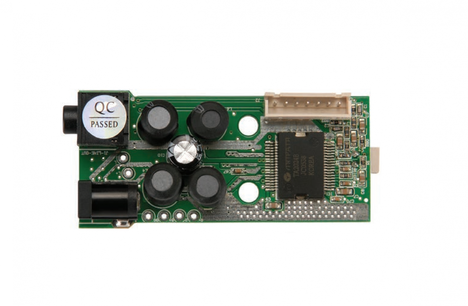
The Class-T Digital Audio Amplifier is designed around the Tripath TA-2024 IC. The TA2024 is a 15W/ch continuous average two-channel Class-T Digital Audio Power Amplifier IC using Tripath’s proprietary Digital Power Processing™ technology. Class-T amplifiers offer both the audio fidelity of a Class-AB amplifier and the power efficiency of a Class-D amplifier.
This PCB amplifier is ideal for any audio enthusiast who enjoys building and modifying speaker systems. The applications are virtually limitless since this tiny PCB measures a mere 2-11/16″ x 1-5/16″. Build your own speakers or incorporate the amplifier into an existing speaker cabinet.
Features
- Class-T architecture
- “Audiophile” Quality Sound• 0.03% THD+N @ 9W, 4• 0.10% IHF-IM @ 1W, 4• 11W @ 4, 0.1% THD+N• 6W @ 8, 0.1% THD+N
- High Efficiency• 81% @ 15W, 4• 90% @ 10W, 8
- Dynamic Range = 98 dB
- Over-current protection
- Over-temperature protection
- High Power• 15W @ 4, 10% THD+N• 10W @ 8, 10% THD+N
Package Contents:
(1) Class T Digital Audio Amplifier PCB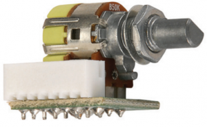 (1) Volume control PCB with 12″ ribbon cable
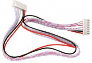 (1) LED power indicator
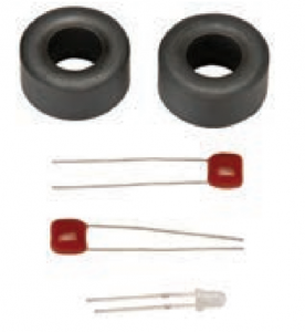 (2) 12″ Speaker Wires (Red & Black)
 (2) 12″ Power Wires (1 Red & 1 Black)(2) 12″ LED Wires (1 Red & 1 Black)(2) Output Capacitors(2) Ferrite Cores
Assembly

- Remove the amplifier PCB from the static protective sleeve using static protective gloves or wrist band
- Solder the speaker wires to the PCB at points “A & B”
- There are polarity marks (L+/- R+/-) printed on the bottom of the PCB
- Solder the power leads (if desired) at point “C”
- There are polarity marks (B+/B-) printed on the bottom of the PCB
- Solder the LED to the PCB at point “D” or use the LED wires to place the LED where desired
- The anode (+) lead is long, the cathode (-) is short

- Mount the LED from the bottom of the PCBInsert the anode through the left eyelet and the cathode through the right eyelet
- Wrap each speaker wire through a ferrite core; one wrap per core is all that is required
- Solder the speaker wires to the speaker terminals
- Solder an output capacitor across the speaker terminals in parallel with the speaker wires
- Connect power via the power leads or DC power jack; we recommend a 12VDC, 2000mA power supply similar to Parts Express model 120-052
- Mount the volume control in the desired location and connect to the amplifier PCB using the 12” ribbon cable
- Mount the PCB using adhesive pads or with a zip tie
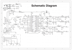
Schematic Diagram
The schematic diagram on back is provided for reference. It illustrates the TA 2024 IC and the input and output circuits on the PCB. CDO are two output capacitors. These capacitors are ideally placed close to the speaker terminals or crossover input terminals as appropriate.

References
[xyz-ips snippet=”download-snippet”]