FTS14, FTS14KS Communication Interface
GB30 014 065 – 2FTS14 communication interface FTS14KS
Only skilled electricians may install this electrical equipment otherwise there is the risk of fire or electric shock!
Temperature at mounting location: -20°C up to +50°C. Storage temperature: -25°C up to +70°C. Relative humidity: annual average value <75%.
valid for devices from production week 07/22 (see bottom side of housing)
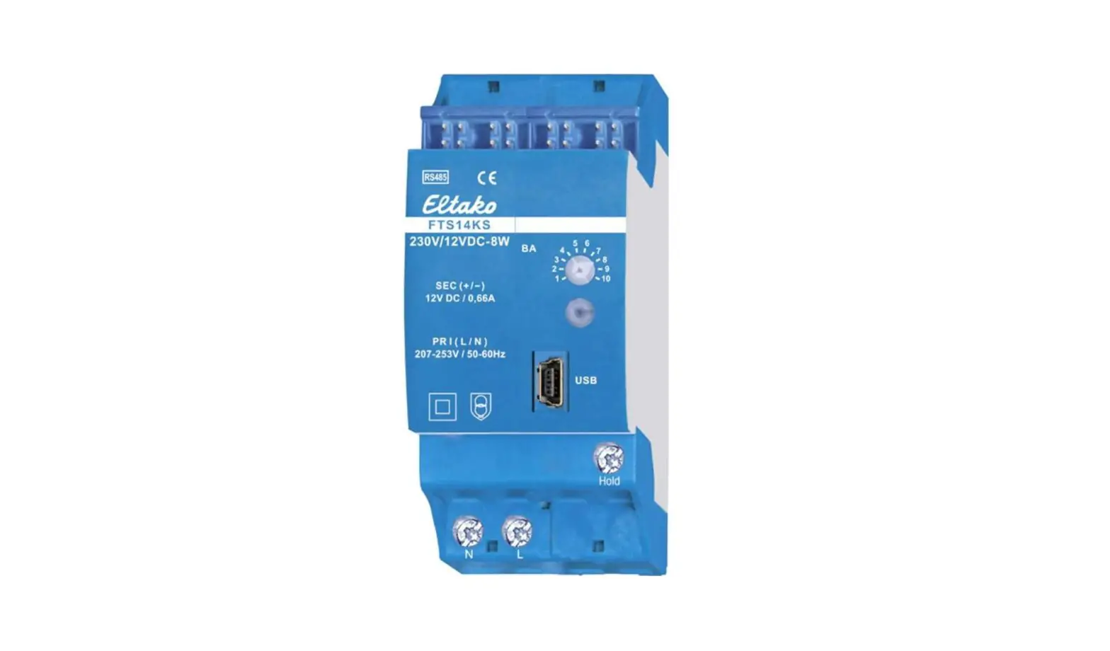
FTS14 communication interface for the Eltako RS485 bus with enclosed power supply FSNT14-12V/12W. Only 0.4 watt standby loss.
Modular device for DIN-EN 60715 TH35 rail mounting. 1 module = 18 mm wide, 58 mm deep.
Supply voltage 12 V DC.
Connection to the Eltako RS485 bus. Bus wiring and power supply with jumpers.
The delivery includes 1 power supply FSNT14-12V/12W, 1 spacer DS14, 2 terminators with printing , 1/2 module, 3 jumpers 1 module (including 1 spare), 1 jumper 1,5 TE, 2 jumpers 1/2 module (including 1 spare) and 1 jumper installation tool SMW14.
If the power supply is subjected to a load of more than 4 W, a ventilation distance of ½ to neighboring devices must be maintained on the left side. With a load greater than 6 W, a ½ ventilation gap is also required between the FSNT14 and the FAM14 with the DS14 spacer. A DS14 spacer and a long jumper are therefore included. If the total power requirement of a series 14 bus system is higher than 10 W, an additional FSNT14-12V/12W must be used for every 12 W of additional power.
Optionally, 12 V DC can also be supplied at the GND/+12 V terminals.
Connection to the Eltako-RS485 bus. Bus
ii
ij
cross wiring and power supply with jumper. The attached second terminator should be plugged to the last actuator. Mini USB to connect to a PC, to create an equipment list, to configurate the actuators using the PC tool PCT14 and for data backup. All FTS14EM and if needed gateways FGW14 will be connected to the terminal Hold when they connect a PC with a RS232 bus. According to the operating manual 10 different operating modes can be set with the operating mode rotary switch BA.Mode switchWhen the rotary switch is set to position 1, a bus scan can be performed. Then addresses (1..126) for new actuators will be assigned which were successively set to LRN. The bottom LED ashes red, when an address was assigned the LED ashes green for 5 seconds. When the rotary switch is set to position 2 or after switching on the supply voltage, a bus scan is performed and a scan list is created. Then confirmation telegrams of actuators are cyclically scanned by scan list. The bottom LED ashes red and lights up green for a short period if a telegram was sent. After the rotary switch is turned to position 3 or after the supply voltage is applied, a bus scan is performed and a scan list is created. Then confirmation telegrams of actuators are cyclically scanned by scan list. The bottom LED ashes red. Pos. 4: function like position 3 but also status telegrams of the actuators are requested. Pos. 5: confirmation telegrams of actuators are cyclically scanned by the device list that was created in the PC tool PCT14. The lower LED brie y lights up green when a confirmation telegram has been received. Pos. 6: confirmation telegrams of actuators are cyclically scanned by the device list that was created in the PC tool PCT14. Pos. 7: function like position 6 but also status telegrams of the actuators are requested. Pos. 8: Unidirectional, not suitable for operation with FSU14 or FGSM14.
Pos. 9: teaching-in wireless timer FSU14 in wireless actuators. Reading and writing of the base ID of FTS14KS with PC tool PCT14.Pos. 10: teaching-in of the wireless timer FSU14 into bus actuators. Control master operation with PC-Tool PCT14. The lower LED ashes green and ickers during bus operation.The bottom LED lights up green if a connection from the PC tool PCT14 was created. When reading or writing date the LED ashes green. The green LED goes out if the connection from the PC tool PCT14 was terminated.Assign device address for actuators: The rotary switch on the FTS14KS is set to position 1, its lower LED ashes red.The rotary switch of the first actuator is set to LRN, the LED on the actuator ashes smoothly.After the address of the FTS14KS was assigned, its lower LED ashes green for 5 seconds and the LED of the actuator goes out. Then set the second actuator to LRN etc.Caution! The bottom rotary switch of the FSR14.. has to be on one channel.Configurate FTS14KS: The following points can be configured with the PC tool PCT14:create device listCAUTION! Don’t forget ‘disconnect FTS14KS’ in the PC tool PCT14. While the connection from the PC tool PCT14 to the FTS14KS exists, no wireless commands are executed.
Typical connection
!
Attention! Follow exactly this installation
procedure:
1. Place all devices on the DIN rail.
2. Fasten the devices right and left with end
clamps for DIN rail.
3. Connect all cables and wires.
4. Insert the jumpers, to do that, place the
jumper into the tool SMW14 and connect it
on the devices.
Manuals and documents in further languages
http://eltako.com/redirect/FTS14KS
1. App 2.
3. www.
For connecting or removing the jumpers, only use the jumper installation tool SMW14 and move vertically to the DIN rail.
The enclosed second terminator of the FTS14KS must be plugged to the last actuator.
Must be kept for later use! We recommend the housing for operating instructions GBA14.Eltako GmbHD-70736 Fellbach Technical Support English:+49 711 94350025 technical-support@eltako.de eltako.com34/2022 Subject to change without notice.
References
[xyz-ips snippet=”download-snippet”]