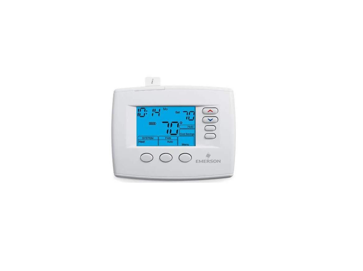
EMERSON 1F85-0477 Blue 4” Universal
Thermostat Instruction Manual
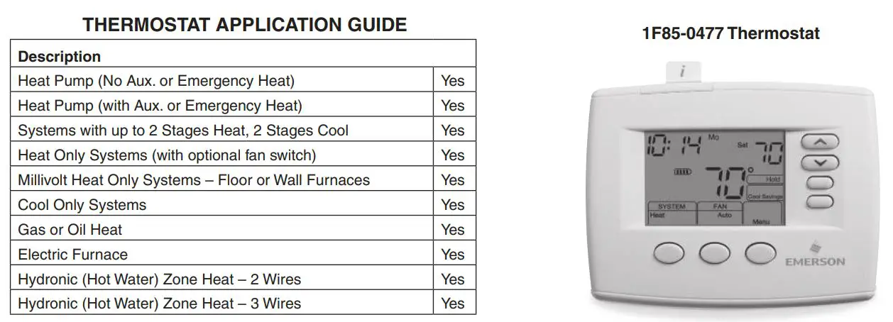
APPLICATIONS
SPECIFICATIONSElectrical Rating:Battery Power …. mV to 30 VAC, NEC Class II, 50/60 Hz or DCInput-Hardwire … 20 to 30 VACTerminal Load ….. 1.5 A per terminal, 2.5A maximum all terminals combinedSetpoint Range … 45° to 90°F (7° to 32°C)Differential (Single Stage) ….. Heat 0.6°F; Cool 1.2°F (adjustable)Differential (Heat Pump) …. Heat 1.2°F; Cool 1.2°F (adjustable)Operating Ambient …. 32° to +105°F (0° to +41°C)Operating Humidity … 90% non-condensing max.Shipping Temperature Range ….. -40° to +150°F (-40° to +65°C)Dimensions Thermostat…….. 3-7/8″H x 5-1/8″W x 1-1/4″D
![]() CAUTIONTo prevent electrical shock and/or equipment damage, disconnect electric power to system at main fuse or circuit breaker box until installation is complete.
CAUTIONTo prevent electrical shock and/or equipment damage, disconnect electric power to system at main fuse or circuit breaker box until installation is complete.
ATTENTION: MERCURY NOTICEThis product does not contain mercury. However, this product may replace a product that contains mercury.Mercury and products containing mercury must not be discarded in household trash. Do not touch any spilled mercury. Wearing non-absorbent gloves, clean up any spilled mercury and place in a sealed container. For proper disposal of a product containing mercury or a sealed container. Refer to www.thermostat-recycle.org for location to send product containing mercury.
INSTALLATION
![]() WARNINGThermostat installation and all components of the control system shall conform to Class II circuits per the NEC code.
WARNINGThermostat installation and all components of the control system shall conform to Class II circuits per the NEC code.
Remove Old ThermostatA standard heat/cool thermostat consists of three basic parts:
- The cover, which may be either a Snap-On or hinge type.
- The base, which is removed by loosening all captive screws.
- The switching subbase, which is removed by unscrewing the mounting screws that hold it on the wall or adapter plate. Before removing wires from old thermostat, label each wire with the terminal designation from which it was attached. Disconnect the wires from the old thermostat one at a time. Do not let wires fall back into the wall.
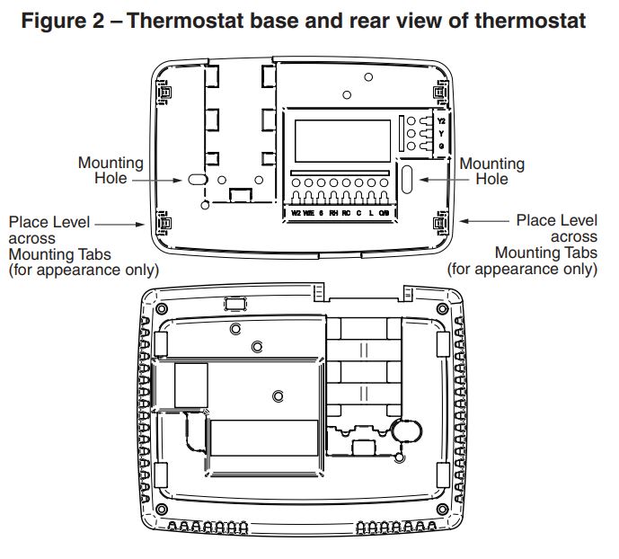
Installing New Thermostat
- Pull the thermostat body off the thermostat base. Forcing or prying on the thermostat will cause damage to the unit.
- Place base over hole in wall and mark mounting hole locations on wall using base as a template.
- Move base out of the way. Drill mounting holes. If you are using existing mounting holes and the holes drilled are too large and do not allow you to tighten base snugly, use plastic screw anchors to secure the base.
- Fasten base snugly to wall using mounting holes shown in Figure 2 and two mounting screws. Leveling is for appearance only and will not affect thermostat operation.
- Connect wires to terminal block on base.
- Push excess wire into wall and plug hole with a fire resistant material (such as fiberglass insulation) to prevent drafts from affecting thermostat operation.
- Carefully line the thermostat up with the base and snap into place.
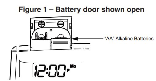
Batteries2 “AA” alkaline batteries are included with the thermostat. To install the batteries, pull the battery door as shown by the arrow and lift open. Using the polarity indicated inside the battery door, insert the batteries. To close the battery door, swing the door down while pulling in the direction of arrow. Once fully down, snap the door back into position. To replace the batteries, set system to OFF.
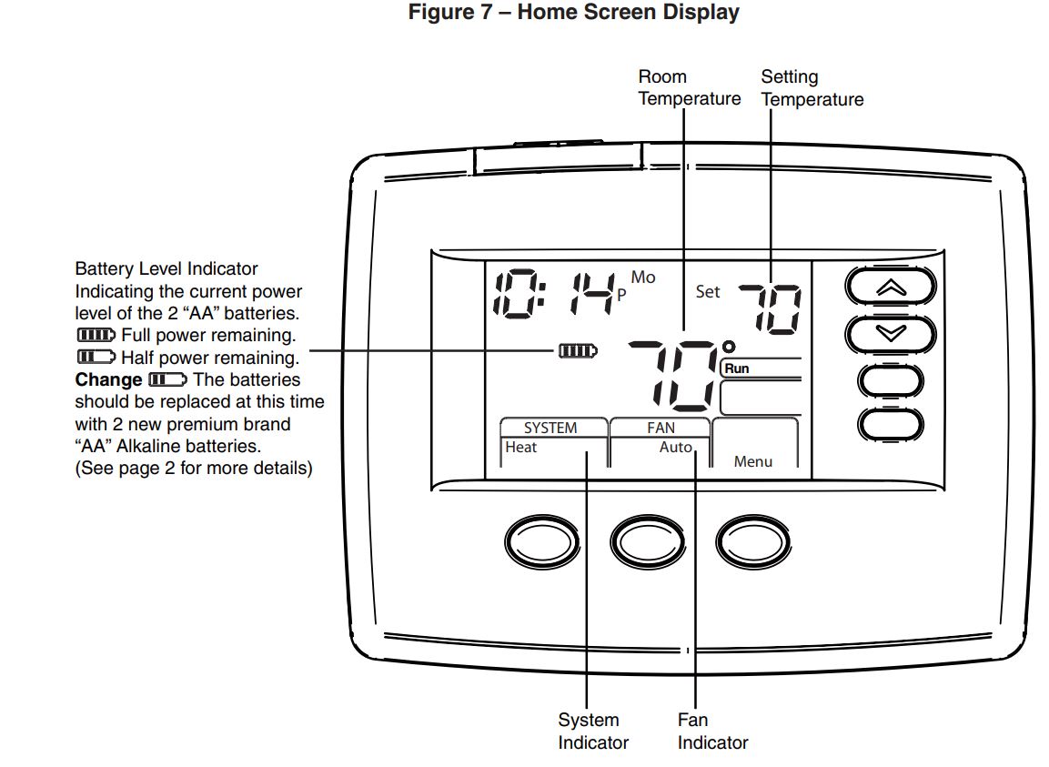
 Thermostat can be powered by system AC power or Battery. If
![]() is displayed, the thermostat is battery powered. If is not displayed, thermostat is system powered with optional battery back-up. When battery power remaining is approximately half, the
is displayed, the thermostat is battery powered. If is not displayed, thermostat is system powered with optional battery back-up. When battery power remaining is approximately half, the![]() will be displayed. When “Change
will be displayed. When “Change![]() ” is displayed, install fresh “AA” alkaline batteries immediately. For best results, replace all batteries with new premium brand alkaline batteries such as Duracell® or Energizer®. We recommend replacing batteries every 2 years. If the home is going to be unoccupied for an extended period (over 3 months) and
” is displayed, install fresh “AA” alkaline batteries immediately. For best results, replace all batteries with new premium brand alkaline batteries such as Duracell® or Energizer®. We recommend replacing batteries every 2 years. If the home is going to be unoccupied for an extended period (over 3 months) and![]() is displayed, the batteries should be replaced before leaving. When less than two months of battery life remain, the setpoint temperature will offset by 10 degrees (10 degrees cooler in Heat mode / 10 degrees warmer in Cool mode). If offset occurs, the normal setpoint can be manually reset with
is displayed, the batteries should be replaced before leaving. When less than two months of battery life remain, the setpoint temperature will offset by 10 degrees (10 degrees cooler in Heat mode / 10 degrees warmer in Cool mode). If offset occurs, the normal setpoint can be manually reset with ![]() or . Another offset will occur within two days if batteries are not replaced.
or . Another offset will occur within two days if batteries are not replaced.
WIRING CONNECTIONS
Refer to equipment manufacturers’ instructions for specific system wiring information. After wiring, see CONFIGURATION section for proper thermostat configuration. Refer to figure 3 through 6 for wiring diagram specifications.
TERMINAL DESIGNATION DESCRIPTIONS
WIRING DIAGRAMS
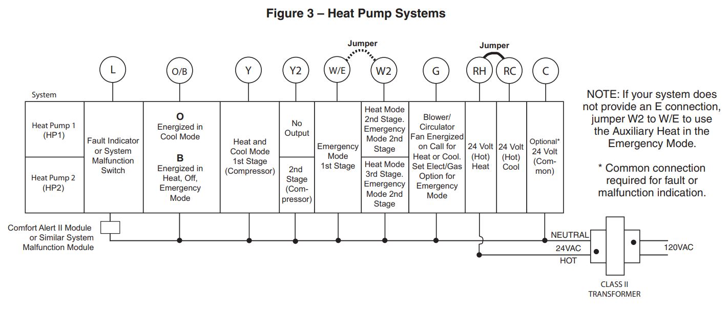
Heat Pump Connections If you do not have a heat pump system, refer to figures 4-6. Refer to equipment manufacturers’ instructions for specific system wiring information. You can configure the thermostat for use with the following heat pump systems.
HEAT PUMP TYPE 1 (HP 1). Single stage compressor system; gas or electric backup. HEAT PUMP TYPE 2 (HP 2). Multi-stage compressor or two compressor system with gas or electric backup. After wiring, see INSTALLER CONFIGURATION section for proper thermostat configuration.
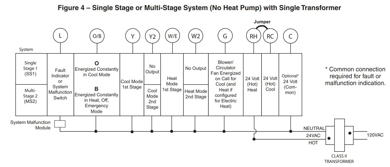
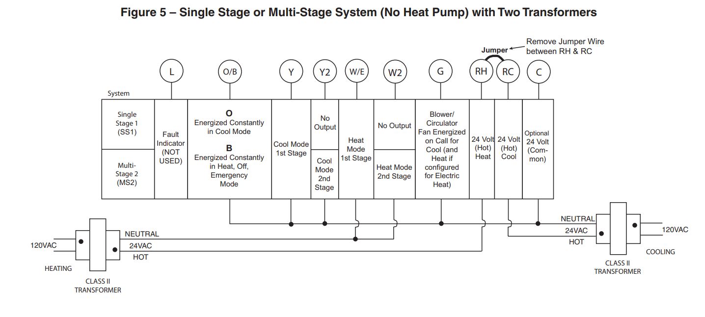
Single Stage and Multi-Stage ConnectionsRefer to equipment manufacturers’ instructions for specific system wiring information. This thermostat is designed to operate a single-transformer or two-transformer system. You can configure the thermostat for use with the following fossil fuel systems:
SINGLE STAGE (SS 1) gas, oil or electric.MULTI-STAGE (MS 2) gas, oil or electric. After wiring, see INSTALLER CONFIGURATION section for proper thermostat configuration.
 THERMOSTAT QUICK REFERENCE
 THERMOSTAT QUICK REFERENCE
Home Screen Description
Programming and Configuration Items
- “System On” indicates when heating or cooling stage is energized. “System On +2” indicates when a second stage is energized.
- The word “Hold” is displayed when the thermostat is in the Hold mode. “Temp Hold” is displayed when the thermostat is in a Temporary Hold mode.
- Displays “Change Filter” when the system has run for the programmed filter time period as a reminder to change or clean your filter.
- Displays “Set” for setpoint when in Run Program mode.
- Displays System Mode (Heat, Me, Auto, Cool, Off) or “Time” in Menu Mode.
- Displays Fan Mode (On, Auto) in Menu Mode.
- Displays “Set Schedule”, “Schedule”, or “Menu”.
- Displays “Save” when Cool Savings™ is working.
- Displays “Heat Pump” when system is configured as Heat Pump thermostat.
- Displays “Hold” in programmable mode. When not in Hold mode, displays “Run” in program run mode.
- Initially displays “Auto Sched”. If Auto Schedule had been used or disabled, then it displays “Cool Savings” when in the Cool Mode if Cool Savings has been enabled in the menu.
- “Call For Service” indicates a fault in the heating/ cooling system, it does not indicate a fault in the thermostat.
- Alternates Time of Day and “LOC” when keypad lockout is enabled.

With thermostat in Heat, Cool or Auto, in normal operation, press the Menu button for at least 5 seconds. The display will show item #1 in the table below. Press Menu button to advance to the next menu item. Press ![]() to change an item option.
to change an item option.
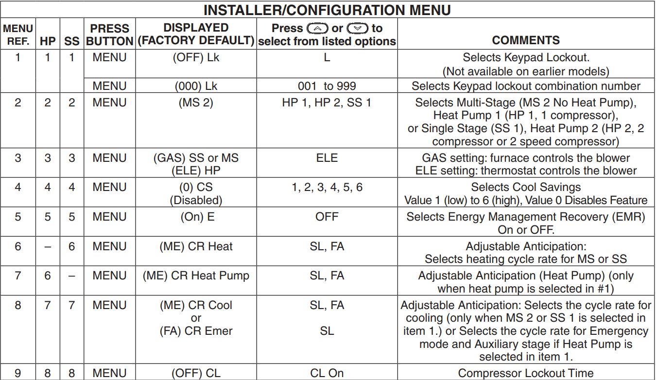

- Keypad Lockout – This menu selection will display “Lk” and “OFF” (default, keypad not locked out). The and are used to toggle the selection between OFF and “L” (keypad locked out). When the keypad lockout selection is enabled “L”, and the MENU button is pressed again, the display will indicate the number “0” (default, still disabled) in the time digits. The and are used to set the combination number from 0 to 999. If a combination of 0 is selected and the MENU button is pressed, the menu will be exited and keypad will not be locked. If 1 to 999 is selected and the MENU button is pressed, the combination is stored into memory and the menu is exited. The “Lk” will display designating keypad locked with a valid combination. The SYSTEM button will operate for 10 seconds after the menu mode is exited to allow the user to change the mode from “OFF” to the desired SYSTEM mode.While the keypad is locked out, a press of MENU will enter the configuration menu. The first menu item displayed is the combination code “0”. The keys are used to set the combination unlock number from 0 to 999. If the unlock number matches exactly with the combination lock number stored in memory when the MENU button is pressed, the keypad is unlocked and the “Lock” is removed. If the unlock number does not match when the MENU button is pressed, the combination returns to “0” for another attempt to set the unlock code. To exit the menu without unlocking the keypad, press RUN SCHED.To reset the combination code and unlock the keypad if the code is forgotten, see troubleshooting section.
- This control can be configured for:MS 2 – Multi-Stage System (no heat pump)HP 1 – Heat Pump with one stage of compressorHP 2 – Heat Pump with two stage compressor or two compressor system, Gas or Electric backupSS 1 – Single Stage System
- GAS or Electric (ELE) fan operation. If the heating system requires the thermostat to energize the fan, select ELE. Select GAS if the heating system energizes the fan on a call for heat.
- Select Cool Savings™ value – Selects the amount of adjustment for the Cool Savings™ feature in Cool mode with 1 (1°) being the least amount of adjustment and 6 (6°) being the most amount of adjustment. Default value is 0 which disables this feature. Selecting a value greater than 0 will display Cool Savings on the screen and enable the key for Cool Savings feature. Cool Savings is an optional energy saving feature that can reduce your cooling costs. It is based on the principal that lower indoor humidity makes a slightly higher temperature feel more comfortable. Cool Savings operates during periods of high demand which normally occur on the hottest summer days when a cooling system may run for hours to reach the thermostat setting. Long cooling run times also lower the indoor humidity. Cool Savings, very slowly, adjusts the setpoint temperature to make the setpoint closer to the displayed room temperature, to a maximum of the number of degrees you select. Adjusting the setpoint temperature over a long cooling run time allows the system to reach your set temperature and turn off. The room temperature will actually be higher than the thermostat displays but the reduction in humidity will allow comfort at the slightly higher temperature.To turn this feature on in the Cool mode press Cool Savings. The display will show “Save” next to the setpoint temperature. When Cool Savings is making adjustments to the room temperature display “Save” will be flashing and the displayed room temperature may vary within the adjustment range you selected.If “Save” is not displayed and this feature is OFF, no change will occur when the cooling system is continuously running during periods of high demand.
- 5) Energy Management Recovery: Energy Management Recovery (E) On enables the thermostat to start heating or cooling early to make the building temperature reach the program setpoint at the time you specify. Heating will start 5 minutes early for every 1° of temperature required to reach setpoint. Example: E On is selected and your heating is pro- grimed to 65° at night and 70° at 7 AM. If the building temperature is 65°, the difference between 65° and 70° is 5°. Allowing 5 minutes per degree, the thermostat setpoint will change to 70° at 6:35 AM. Cooling allows more time per degree, because it takes longer to reach set temperature.
- Cycle Rate Selection The factory default setting for Heat and Cool modes, SS1, MS2, is medium cycle (ME). For Heat Pump, HP1, HP2, the default setting is medium (ME). For Emer (Aux) the default setting is fast cycle (FA). To change cycle rate, press the or key. Cycle rate differentials for different settings are:
- Select Compressor Lockout CL OFF or ON – Selecting CL ON will cause the thermostat to wait 5 minutes between cooling cycles. This is intended to help protect the compressor from short cycling. Some newer compressors already have a time delay built in and do not require this feature. Your compressor manufacturer can tell you if the lockout feature is already present in their system. When the thermostat compressor time delay occurs, it will flash the setpoint for up to five minutes.
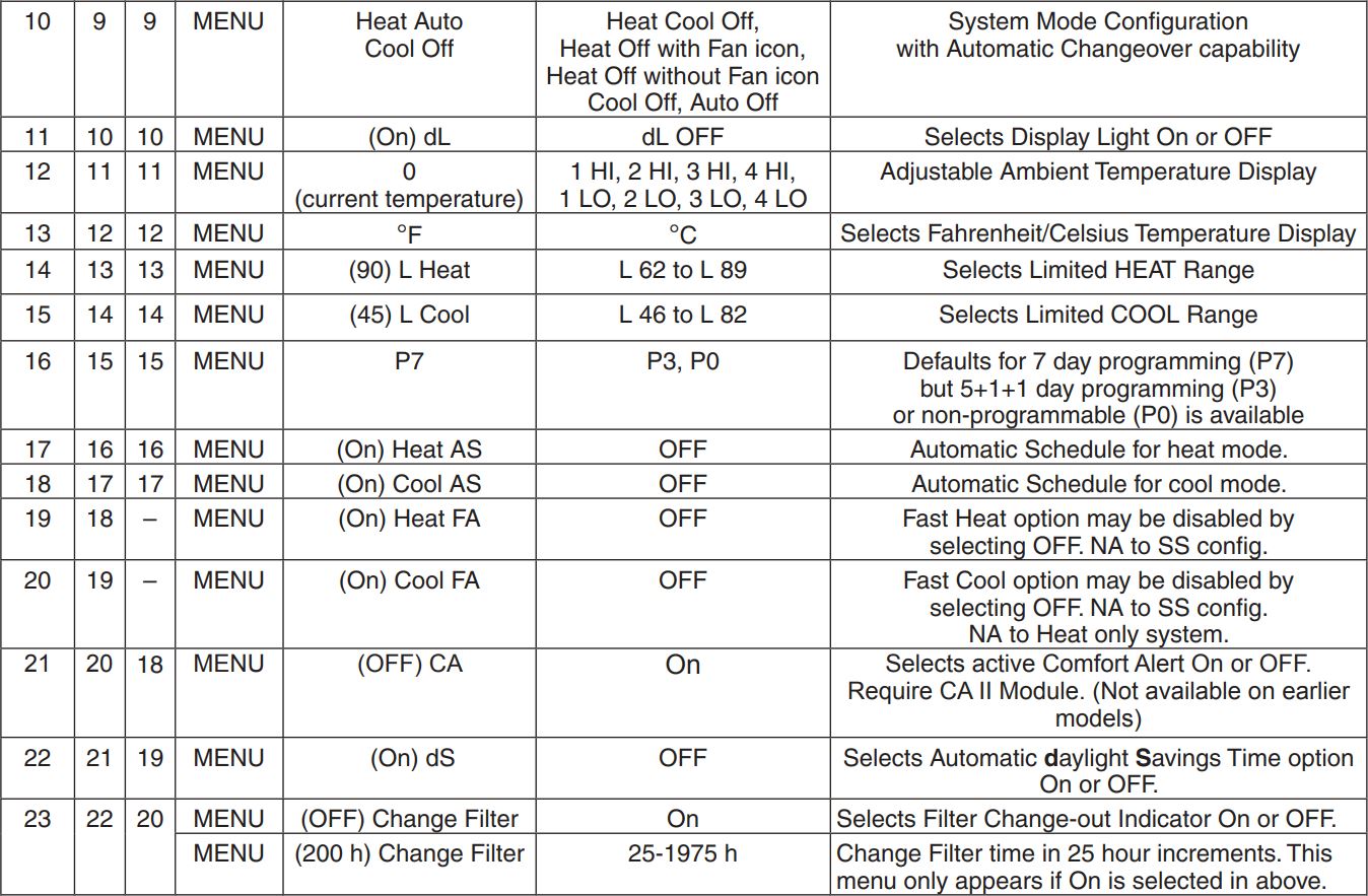
- System Mode Configuration – This thermostat is configured for Heat and Cool (SYSTEM switch with Cool, Off, Heat) default. It can also be configured for Heat and Cool with Auto changeover (Heat, Auto, Cool, Off), Heat only with fan (Off, Heat), Heat only without fan, Auto only (Auto, Off), and Cool only (Cool, Off).
- Select Backlight Display – The display backlight improves display contrast in low lighting conditions. When the “C” terminal is powered, selecting backlight CD ON will keep the light on continuously. Select backlight OFF will turn the light on momentarily after any key is pressed. When the “C” terminal is not powered, the light will be on momentarily after any key is pressed no matter whether the backlight is selected ON or OFF.
- Select Temperature Display Adjustment 4 LO to 4 HI– Allows you to adjust the room temperature display up to 4° higher or lower. Your thermostat was accurately calibrated at the factory, but you have the option to change the display temperature to match your previous thermostat. The current or adjusted room temperature will be displayed.
- Select F° or C° Readout – Changes the display readout to Celsius or Fahrenheit as required.
- Temperature Limit Range Heat or Cool – This selection sets the maximum HEAT (13) or minimum COOL (14) temperature for the setpoint range. Select the limit temperature using the or keys. In the Run mode, the setpoint temperature will not adjust past the limit temperature selected. When the limit temperature is reached, trying to raise lower the setpoint past the limit will cause “L” to be displayed in the times digits for about 6 seconds. This feature not available on earlier models.
- Program Options: Configured for 7 day or 5+1+1 day programming or non-programmable mode. The default setting is P7, indicating 7 day programming. The programs per week can be changed to P3 or P0 by pressing9) Select Compressor Lockout CL OFF or ON Select-the keys. A selection of 0 Days for non-programmable will eliminate the need for EMR, and that step in the menu will be skipped.
- Select Automatic Schedule – With just one touch of the AUTO SCHEDULE button this feature allows you to program a desired comfort temperature into all the program periods along with a 6° set back for night periods of both Heat and Cool programs. Factory default is “On” for both. When Heat AS On and Cool AS On are activated while in Heat or Cool mode, select desired setpoint temperature and press AUTO SCHEDULE. This value will be copied into all the morning, day and evening program periods. The night program periods will have a 6°F set back.
- Select Fast Second Stage ON or OFF – Heat pump or Multi-stage only, in the run mode, with the fast Heat feature enabled (FA Heat On), if the Heat setpoint temperature is manually raised by 3°F (2°C) or more above the actual temperature using the second stage will energize immediately. With FA OFF, second stage will not energize until the setpoint temperature is 1°F or more above actual temperature for more than ten minutes. The Fast Cool feature (FA Cool) provides the same controls when the setpoint temperature is lowered.
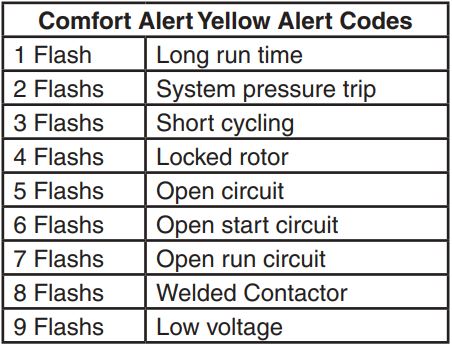
- Comfort Alert with Active Protection – Turn this feature ON to enable active protection. This allows the thermostat to identify fault codes sent by the Comfort Alert module when compressor damage is possible and react to those codes by turning the compressor off. Fault codes from the Comfort Alert module will flash on the thermostat. (Refer to Comfort Alert Yellow Alert Codes in Troubleshooting section.) If a Comfort Alert module isnot connected, or to disable active protection, turn this feature OFF. If a Comfort Alert module is connected and this feature is turned OFF, the thermostat will still receive and flash the fault codes from the Comfort Alert module, but the active protection will not be enabled to protect the compressor.
- Select Daylight Saving Time Calculation – This feature will allow the thermostat to calculate the DST automatically and apply it to the Real Time Clock display. Default On. Use buttons to select the feature OFF.
- Select Filter Replacement Reminder and Set Run Time – Select the “Change Filter” reminder On or OFF. If selected On, press MENU to select the time period from 25 to 1975 hours in 25 hours increments. In a typical system, 200 hours (default) of run time is approximately 30 days. After the selected time of bloweroperation, the thermostat will display “Change Filter” as a reminder to change or clean your air filter. When “Change Filter” is displayed, press MENU or RUN button to clear the display and restart the time to the next filter change.
- Select Reversing Valve Output – The O/B option is factory set at “O” position. This will accommodate the majority of heat pump applications, which require the changeover relay to be energized in COOL. If the thermostat you are replacing or the heat pump being installed with this thermostat requires a “B” terminal, to energize the changeover relay in HEAT, the O/B option should be set at “B” position.

OPERATING YOUR THERMOSTAT
IMPORTANT!
Choose the Fan Setting (Auto or On)Press the FAN button to Auto or On. Fan Auto is the most commonly selected setting and runs the fan only when the heating or cooling system is on. Fan On runs the fan continuously for increased air circulation or to allow additional air cleaning.
Choose the System Setting (Heat, Off, Cool, Auto, Emer)Press the SYSTEM button to select:Heat: Thermostat controls only the heating system.Off: Heating and Cooling systems are off.Cool: Thermostat controls only the cooling system.Auto: Auto Changeover is used in areas where both heating and cooling may be required on the same day. AUTO allows the thermostat to automatically select heating or cooling depending on the indoor temperature and the selected heat and cool temperatures. When using AUTO, be sure to set the Cooling temperatures more than 1° Fahrenheit higher than the heating temperature.Me: (Heat Pump models) Thermostat controls only backup heating system.
Manual Operation (Bypassing the Program)Programmable ThermostatsPress ![]() and then the HOLD button and adjust the temperature wherever you like. This will override the program. The HOLD feature bypasses the program and allows you to adjust the temperature manually, as needed. Whatever temperature you set in HOLD will be maintained 24 hours a day, until you manually change the temperature or press RUN to cancel HOLD and resume the programmed schedule.
and then the HOLD button and adjust the temperature wherever you like. This will override the program. The HOLD feature bypasses the program and allows you to adjust the temperature manually, as needed. Whatever temperature you set in HOLD will be maintained 24 hours a day, until you manually change the temperature or press RUN to cancel HOLD and resume the programmed schedule.
Program Override (Temporary Override)Press ![]() buttons to adjust the temperature. This will override the temperature setting for four hours. To cancel the temporary setting at any time and return to the program, press RUN. If the SYSTEM button is pressed to select AUTO the thermostat will change to Heat or Cool, whichever ran last. If it switches to heat but you want cool, or it changes to cool but you want heat, press both
buttons to adjust the temperature. This will override the temperature setting for four hours. To cancel the temporary setting at any time and return to the program, press RUN. If the SYSTEM button is pressed to select AUTO the thermostat will change to Heat or Cool, whichever ran last. If it switches to heat but you want cool, or it changes to cool but you want heat, press both ![]() buttons simultaneously to change to the other mode.
buttons simultaneously to change to the other mode.
Second Stage Time DelayYour thermostat is designed to determine the optimum time to activate the second stage. Simply raising the temperature in heating or lowering it in cooling will not always force the thermostat to bring the second stage on quickly. There is a time delay from 0-30 minutes depending on the performance of the first stage of the system.
EXAMPLE: For the last 2 hours the thermostat is set on 70° and the room temperature is 70° with the equipment using only the first stage of heat. Since the equipment is keeping the temperature within 1° of setpoint, the thermostat will delay second stage for a longer time if you manually raise the temperature or if the room temperature quickly changes. Once the second stage comes on, it will come on sooner the next time there is a difference between the setpoint and the room temperature. The net effect of the staging program is that when the first stage is capable of making temperature the second stage will delay longer. When the thermostat calculates that first stage cannot make temperature in a reasonable time, the second stage will come on sooner. This built in function automatically optimizes the use of additional stages of heat or cool.
PROGRAMMING
Set Current Time and Date
- Press Menu and then Time button once. The display will show the hour only.
- Press and hold either the or button until you reach the correct hour and AM/PM designation (AM begins at midnight, PM begins at noon).
- Press TIME once again. The display window will show the minutes only.
- Press and hold either the or button until you reach the correct minutes.
- Additional presses of TIME will advance the display to show the year, month and date of month. Press the or button to change the display to the correct setting for each.
- Press RUN to exit the TIME mode.
Enter the Heating Program
- Press SYSTEM button to select “Heat” in the system switch area indicating the active mode being programmed.
- Press the MENU button and then press SCHEDULE.
- The top of the display will show the day(s) being programmed. The time and temperature (flashing) are also displayed. “1” will also be displayed to indicate the period.
- Press button to change the temperature to your selected temperature for the 1st heating period.
- Press TIME button, time will flash.
- Press button to adjust the start time for the1st period.
- The time will change in 15 minute increments.
- After you have set the time and the temperature for the period to begin, press SCHEDULE to advance to the next program period.
- Repeat steps 2 through 8 until all of the program times and temperatures are set for all program periods on that day.
- Press SCHEDULE to the next day and repeat steps 2 through 9.
- When programming is complete and all of the times and temperatures match your desired heating schedule, press RUN. The thermostat will now run your program.
Enter the Cooling Program
- Press SYSTEM button to select “Cool” in the system switch area indicating the active mode being programmed.
- Follow Enter Heating Program instructions for entering cooling times and temperatures.
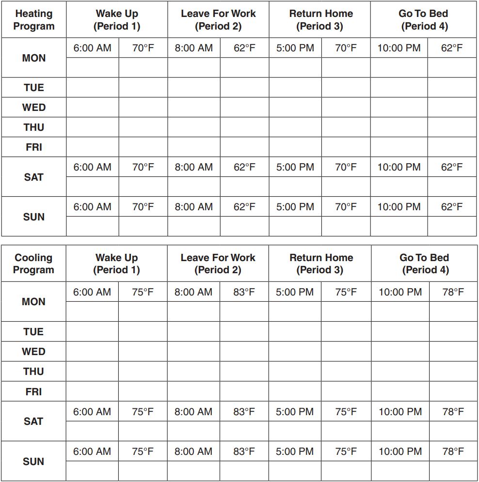
Energy Saving Factory Pre-ProgramThe programmable thermostats are programmed with the energy saving settings shown in the table below for all days of the week. If this program suits your needs, simply set the thermostat clock and press the RUN button. The table below shows the factory set heating and cooling schedule for all days of the week.
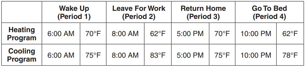
Planning Your Program ImportantThe Heating and Cooling Program schedules below allow you to pencil in your own program times and temperatures. The thermostat comes configured for 7 day programming and can also be configured for 5+1+1 day programming (see configuration section).
Factory settings are listed on Monday through Friday, Saturday and Sunday. If you are re-programming a 7 day schedule, pencil in all lines with the times and temperatures you want.
If you are re-programming a 5+1+1 fill in your own times and temperatures directly below the factory times and temperatures.Keep the following guidelines in mind when planning your program. ·
- In Heating, lower temperatures will save energy.
- In Cooling, higher temperatures will save energy.
- If you plan on using Auto Changeover, do not program the heating higher than the cooling.
Worksheet for Re-Programming 7 Day and 5+1+1 Day Program
TROUBLESHOOTING
Comfort Alert Codes The Comfort Alert diagnostics product monitors the air conditioning outdoor systems with single phase Copeland Scroll compressors. Abnormal system and electrical conditions are indicated by flashing ALERT codes on the yellow LED on the Comfort Alert module. The flash codes are transmitted to the thermostat by the Comfort Alert Thermostat interface module. The Comfort Alert compatible thermostat displays “Call For Service” that flashes at the same rate as the yellow LED on the Comfort Alert module.
Reset Operation Note: When thermostat is reset, installer configuration menu settings and programming will reset to factory settings. If a voltage spike or static discharge blanks out the display or causes erratic thermostat operation, you can reset the thermostat by removing the wires from terminals R and C (do not short them together) and removing batteries for 2 minutes. After resetting the thermostat, replace the wires and batteries. If the thermostat has been reset and still does not function correctly contact your heating/cooling service person or place of purchase.Note: Be sure to review the installer configuration menu settings.To reset the programming, clock and configuration settings, press ![]() and the FAN button simultaneously. The thermostat should go blank and then all segments will be displayed momentarily.
and the FAN button simultaneously. The thermostat should go blank and then all segments will be displayed momentarily.

HOMEOWNER HELP LINE: 1-800-284-2925
White-Rodgers is a business of Emerson Electric Co.The Emerson logo is a trademark and service mark o1f2Emerson Electric Co.
![]()
www.white-rodgers.comwww. emersonclimate.com
 report this ad
![]()
References
[xyz-ips snippet=”download-snippet”]