
User Manual
Copeland Scroll Compressors for CO2 Subcritical Refrigeration R-744
Safety Instructions
Copeland Scroll™ compressors are manufactured according to the latest U.S. and European Safety Standards. Particular emphasis has been placed on the user’s safety. Safety icons are explained below and safety instructions applicable to the products in this bulletin are grouped on Page 3. These instructions should be retained throughout the lifetime of the compressor. You are strongly advised to follow these safety instructions.
Safety Icon Explanation
![]()
Instructions Pertaining to Risk of Electrical Shock, Fire, or Injury to Persons.
 WARNING
ELECTRICAL SHOCK HAZARD
- Disconnect and lock out power before servicing.
- Discharge all capacitors before servicing.
- Use compressor with grounded system only.
- Molded electrical plug must be used when required.
- Refer to original equipment wiring diagrams.
- Electrical connections must be made by qualified electrical personnel.
- Failure to follow these warnings could result in serious personal injury.
WARNING
![]()
PRESSURIZED SYSTEM HAZARD
- System contains refrigerant and oil under pressure.
- Remove refrigerant from both the high and low compressor side before removing compressor.
- Never install a system and leave it unattended when it has no charge, a holding charge, or with the service valves closed without electrically locking out the system.
- Use only approved refrigerants and refrigeration oils.
- Personal safety equipment must be used.
- Failure to follow these warnings could result in serious personal injury.
WARNING
BURN HAZARD
- Do not touch the compressor until it has cooled down.
- Ensure that materials and wiring do not touch high temperature areas of the compressor.
- Use caution when brazing system components.
- Personal safety equipment must be used.
- Failure to follow these warnings could result in serious personal injury or property damage.
CAUTION
COMPRESSOR HANDLING
- Use the appropriate lifting devices to move compressors.
- Personal safety equipment must be used.
- Failure to follow these warnings could result in personal injury or property damage.
Safety Statements
- Refrigerant compressors must be employed only for their intended use.
- Only qualified and authorized HVAC or refrigeration personnel are permitted to install commission and maintain this equipment.
- Electrical connections must be made by qualified electrical personnel.
- All valid standards and codes for installing, servicing, and maintaining electrical and refrigeration equipment must be observed.
INTRODUCTION
This bulletin describes the operating characteristics, design features, and application requirements for all Copeland Scroll™ compressors for refrigeration applications using CO2 (R-744) for a subcritical operation. For additional information, please refer to the online product information accessible from the Emeson website at Emerson.com/OPI.
Increasing environmental concerns about the potential direct emissions from HFC-based refrigeration systems into the atmosphere have led system designers to revisit refrigerant R-744 (CO2). In comparison with HFC refrigerants, the specific properties of CO2 require changes in the design of the refrigeration system. The ZO range of Copeland Scroll compressors has been designed to exploit the characteristics of CO2 refrigeration systems. The efficiency, reliability and liquid handling advantages of Copeland Scroll technology make it ideal for these applications.
The comparably high pressure level and thermodynamic properties of the refrigerant CO2 have driven system designers towards low temperature cascade systems, where CO2 is used as a direct expanding refrigerant in the low temperature stage. In these subcritical cascade applications, the CO2 compressor in the low temperature stage is still exposed to pressure levels higher than in standard HFC-based systems. However, they are limited to pressure levels similar to those already known from air-conditioning applications with refrigerant R-410A. An HFC refrigerant is typically used in the medium temperature stage of the cascade system.
The challenges for CO2 compressors compared to HFC compressors lie in the high pressure levels, the higher mass flow for a given displacement, and designing for proper lubrication. In terms of mechanical strength, ZO scroll compressors benefit from many years of experience with R-410A air-conditioning compressors, which operate at similar pressure levels as CO2 compressors.
CO2 FOR LOW TEMPERATURE APPLICATIONS SUB-CRITICAL DX SYSTEM
Figure 1 at the end of this bulletin shows a cascade system diagram with HFC refrigerant for the high side and sub-critical CO2 for the low stage refrigerant.
NomenclatureThe model designation contains the following technical information about the compressor:
ZO D 34 K 3 E – TFD – 269
- Z = Compressor family: Scroll
- O = Refrigerant: R744, subcritical operation
- D= Digital Model; Blank= Standard Model
- 34K = Nominal Capacity (kBTU/hr)
- 3 = Model variation
- E = Oil type: POE oil
- TFD = Electrical Description:T= Three PhasesF= Internal Inherent Motor Protection5,7,D,E= Nominal Voltage Range
- 269 = Bill of material
Please refer to Online Product Information at Emerson.com/OPI for details.
Refer to Table 1 for a detailed list of ZO Family Models.
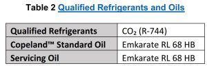
Approved Oils & RefrigerantsRecommended quality for carbon dioxide purity grade is 4.0 [(≥ 99.99 %) H2O≤10ppm, O2≤10ppm, N2≤50ppm] or higher.
Emkarate RL 68 HB is approved for new and service applications. Oil recharge values can be taken from Copeland Scroll™ compressors brochures or Copeland® brand Products Selection Software.
CAUTION
The compressor superheat at suction should be controlled such that it is always above 36°F (20K) to avoid oil dilution in the compressor but low return gas temperature enough to keep the compressor discharge temperature below 250°F (121.1°C), especially at high compressor ratios (high condensing and low evaporating temperatures).
Note: A separate heat-exchanger may be required to maintain the recommended superheat.Refer toTable 2 for reference.
Mounting PartsSpecially designed rubber grommets are available for mounting (Kit 527-0157-00). These grommets are formulated from a high durometer material specifically designed for refrigeration applications. The high durometer limits the compressors motion thereby minimizing potential problems of excessive tubing stress. Sufficient isolation is provided to prevent vibration from being transmitted to the mounting structure. The use of standard soft grommets is not recommended.
Refer Figure 2 for details.Safety Relief Valves
CAUTION
In a closed system filled with CO2 the pressure can rise above 725 psig (50 Bar) under some ambient conditions. The system must be equipped with safety relief valves to ensure that the compressor’s low side and high side pressures are not exceeded (see below). If the unit is shut down for service or other reasons, the pressure will rise due to ambient heat. To prevent the loss of charge at shut down through the relief valves, it is recommended to provide additional cooling to keep the pressure below the maximum standstill pressure of the suction side. This can be achieved using a small auxiliary condensing unit connected to an uninterruptable power supply, that removes heat from the R744 liquid receiver. The auxiliary condensing unit will not be sufficient to maintain the low-stage system below the Maximum Allowable Operation Pressure if there is a load from the evaporators.
Refer to ANSI/ASHRAE Standard 15-2016, Section 9.7.5 and ANSI/ASHRAE 15 appendix C-2016,.
ZO Maximum Operating pressures
Suction side: 500 psig (34.5 Bar)Discharge side: 625 psig (43.1 Bar)
The requirements for Copeland Scroll compressors with CO2 per Underwriters Laboratory (UL) state that a system with a CO2 compressor must be installed with an approved suction pressure relief valve. ASME high-pressure relief valves are the only valves currently approved for use with the Copeland Scroll CO2 models. The installation of the above valve must meet the following criteria:
- There must be an open flow path from the compressor suction sump to the relief valve. This is accomplished by connecting the relief valve to the correct port on the suction Rotalock valve. This port is open to the compressor sump no matter what position the valve stem is located. The relief valve itself can be remotely located as long as the path from compressor suction sump and the valve is always open.
- This flow path cannot be shut off in any way by a valve.
Figure 4 represents the correct (a) and incorrect (b) way to apply the pressure relief valve. Failure to apply the high-pressure relief valve correctly will void any UL approval of the system.
The high-pressure relief valve should be located such that the path between the valve and the low side of the compressor is always open and cannot be shut off in any way by a valve. Note that the valve opens only once and must be replaced if it opens.
A 500 psig (34.5 Bar) high-pressure relief valve kit is shipped with the compressor. Contact Application Engineering for alternative pressure relief valves.
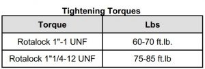
ZO compressors have Rotalock valve fittings. Rotalock shut-off valves are available for the suction as well as discharge side. Using either straight or angled adaptors provides a way to convert a Rotalock into a brazing connection.
High-Pressure Safety Controls

A CO2 approved ASME safety pressure relief valve(s) with a setting of 500 psig (34.5 Bar) is required to be pre-installed for standstill conditions.
All sections that can be isolated in the system must have relief valves pre-installed by the system manufacturer with a 500 psig (34.5 Bar) setting.
These high-pressure cut-outs should have a manual reset feature.
Additional Requirements:
- Low Pressure Cut-Out on Suction Side: 80 psig (5.5 bar)
- High Pressure Cut-Out on Discharge Side: 625 psig (43.1 Bar)
- Discharge Temperature Protection
- External discharge line thermostat 998-7022-02
Active Oil ManagementAn OMC CO2 electronic oil level management system should be used that is suitable for both high and low pressure oil management systems. The differential pressure required for sufficient oil flow from the oil reservoir to the compressor crankcase depends upon the system. However, 20 psig (1.4 Bar) can be used as a minimum pressure differential value. Refer to Figure 3 and Table 4.
For more details about OMB-CO2 Oil Management Devices scan the QR codes below or follow the links available.
- Emerson OMC Video

- Emerson OMC Specification Sheet [PDF]
- OMB/C Instructions [PDF]
- OMB Adapter Instruction Sheet [pdf]


AccumulatorsIrrespective of system charge, oil dilution may occur if large amounts of liquid refrigerant repeatedly flood back to the compressor during normal running cycles, defrost, and varying loads.
If adequate Compressor Superheat cannot consistently be maintained at minimum of 36°F (20K) an accumulator may be required, as well as the addition of liquid to suction heat exchanger or other means as assuring 36°F (20K) Superheat.
ScreensThe use of screens finer than 30 x 30 mesh (0.6 mm openings) anywhere in the system should be avoided with these compressors. Field experience has shown that finer mesh screens used to protect expansion valves, capillary tubes, or accumulators can become temporarily or permanently plugged with normal system debris and block the flow of either oil or refrigerant to the compressor. Such blockage can result in compressor failure.
MufflersExternal mufflers, normally applied to piston compressors in the past, may not be required for Copeland Scroll compressors.
Individual system tests should be performed to verify acceptability of sound performance. If adequate attenuation is not achieved, use a muffler with a larger cross-sectional area to inlet area ratio. A ratio of 20:1 to 30:1 is recommended.
A hollow shell muffler will work quite well. Locate the muffler 6-18 inches from the compressor for the most effective operation. The farther the muffler is placed from the compressor within these ranges, the more effective. Choose a muffler with a length of 2-6 inches.
Electrical Connection

The compressor terminal box has a wiring diagram on the inside of its cover. Before connecting the compressor, ensure the supply voltage, the phases and the frequency match the nameplate data. Refer to Figure 5 for details.
The terminal box is IP21 for all models from ZO21K* to ZO104K*. The ZO Scroll compressors have three-phase induction motors connected in star. Copeland Scroll compressors, like several other types of compressors, will only compress in one rotational direction. Three phase compressors will rotate in either direction depending upon phasing of the power. Since there is a 50% chance of connecting power in such a way as to cause rotation in the reverse direction, it is important to include notices and instructions in appropriate locations on the equipment to ensure that proper rotation direction is achieved when the system is installed and operated. Verification of proper rotation direction is made by observing that suction pressure drops and discharge pressure rises when the compressor is energized. Reverse rotation will result in no pressure differential as compared to normal values.
A compressor running in reverse will sometimes make an abnormal sound. There is no negative impact on durability caused by operating three phase Copeland Scroll compressors in the reversed direction for a short period of time (under one hour). After several minutes of reverse operation, the compressor’s internal overload protector will trip shutting off the compressor. If allowed to repeatedly restart and run in reverse without correcting the situation, the compressor bearings will be permanently damaged because of oil loss to the system.
All three phase scroll compressors are wired identically internally. As a result, once the correct phasing is determined for a specific system or installation, connecting properly phased power leads to the identified compressor electrical (Fusite™) terminals will maintain the proper rotational direction (see Figure 7). All three phase scrolls will continue to run in reverse until the internal overload protector opens or the phasing is corrected.
Crankcase Heaters
A crankase heater is always required. The crankcase heater ust be turned on a minimum of 12 hours prior to starting the compressor and must remain energized during the compressor off cycle.
See Table 3 for reference.
Motor ProtectionFor the ZO range of compressors, conventional inherent internal line break motor protection is provided.
Operating EnvelopeFigure 6 at the end of this bulletin shows the CO2 cascade operating envelope in relation to R-410A and R-404A.
Charging Procedure

Do not operate compressor without enough system charge to maintain at least 87 psig (6 Bar) suction pressure.
Do not operate with a restricted suction.
Do not operate with the low-pressure cut-out bridged.
Vapor initial charge should be 145 PSIG (10 Bar). Do not allow a pressure under 87 psig (6 Bar), otherwise it might cause CO2 solidification and blocked valves or pipes and consequently, the scrolls may overheat and cause early drive bearing damage.
Do not use the compressor to test the opening set point of the high-pressure cut-out. Bearings are susceptible to damage before they have had several hours of normal running in. Ensure charging equipment is approved for at least 1300 psig (89.6 Bar).
The system should be charged through the liquid-receiver shut-off valve or through a valve in the liquid line. The use of a filter drier in the charging line is highly recommended.
Because there may be several valves in the system it is recommended to charge on both the high and low sides simultaneously to ensure a positive refrigerant pressure is present in the compressor before it runs. The majority of the charge should be placed in the high side of the system to prevent bearing washout during first-time start.
Deep Vacuum OperationCopeland Scroll compressors should never be used to evacuate a refrigeration or air-conditioning system. The scroll compressor can be used to pump down refrigerant in a unit as long as the pressures remain within the operating envelope. Low suction pressures will result in overheating of the scrolls and permanent damage to the compressor drive bearing. ZO scrolls incorporate internal low vacuum protection, the floating seal unloads when the pressure ratio exceeds approximately 10:1.
Shell Temperature
The top shell and discharge line can briefly but repeatedly reach temperatures above 350°F (176.7 °C) if the compressor cycles on its internal protection devices. This only happens under rare circumstances and can be caused by the failure of system components such as the condenser or evaporator fan or loss of charge and depends upon the type of expansion control. Care must be taken to ensure that wiring or other materials that could be damaged by these temperatures do not come in contact with the shell.
Pump Down Cycle and Parallel Rack ApplicationA pump down cycle for control of refrigerant migration may be used in conjunction with a crankcase heater when the compressor is located so that cold air blowing over the compressor makes the crankcase heater ineffective.
If a pump down cycle is used on a parallel rack system, a separate external check valve must be added. The scroll discharge check valve is designed to stop extended reverse rotation and prevent high-pressure gas from leaking rapidly into the low side after shut off. The check valve will in some cases leak more than reciprocating compressor discharge reeds, normally used with pump down, causing the scroll compressor to recycle more frequently. Repeated short-cycling of this nature can result in a low oil situation and consequent damage to the compressor. The low-pressure control differential has to be reviewed since a relatively large volume of gas will re-expand from the high side of the compressor into the low side on shutdown.
Low Pressure Safety ControlNever set the low-pressure control to shut off outside of the operating envelope. To prevent the compressor from running into problems during such faults as loss of charge or partial blockage, the control should not be set lower than -60°F (-51.1°C) equivalent suction pressure (80 PSIG, 5.51 bar) below the lowest design operating point.
Minimum Run TimeEmerson recommends a maximum of 10 starts per hour. There is no minimum off time because scroll compressors start unloaded, even if the system has unbalanced pressures. The most critical consideration is the minimum run time required to return oil to the compressor after start-up. To establish the minimum run time, obtain a sample compressor equipped with a sight tube (available from Emerson Climate Technologies) and install it in a system with the longest connecting lines that are approved for the system. The minimum on time becomes the time required for oil lost during compressor start-up to return to the compressor sump and restore a minimal oil level that will ensure oil pick-up through the crankshaft. Cycling the compressor for a shorter period than this, for instance to maintain very tight temperature control, will result in progressive loss of oil and damage to the compressor.
ASSEMBLY LINE PROCEDURES
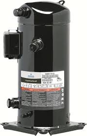
Installing the CompressorCopeland Scroll compressors leave the factory dehydrated and with a positive dry air charge. Plugs should not be removed from the compressor until the compressor has had sufficient time to warm up if stored outside and is ready for assembly in the unit. The suggested warm up time is one hour per 4°F (2K) difference between outdoor and indoor temperature. It is suggested that the larger suction plug be removed first to relieve the internal pressure. Removing the smaller discharge plug could result in a spray of oil out of this fitting since some oil accumulates in the head of the compressor after Emerson’s run test. The inside of both fittings should be wiped with a lint free cloth to remove residual oil prior to brazing. A compressor containing POE oil should never be left open longer than 5 minutes.
Assembly Line Brazing ProcedureFollowing are the proper procedures for brazing the suction and discharge lines to a scroll compressor. It is important to flow nitrogen through the system while brazing all joints during the system assembly process. Nitrogen displaces the air and prevents the formation of copper oxides in the system. If allowed to form, the copper oxide flakes can later be swept through the system and block screens such as those protecting capillary tubes, thermal expansion valves, and accumulator oil return holes. Any blockage of oil or refrigerant may damage the compressor resulting in failure.
New Installations
- The copper-coated steel suction tube on scroll compressors can be brazed in approximately the same manner as any copper tube.
- Recommended brazing materials: Any SIL-FOS® material is recommended, preferably with a minimum of 5% silver. However, 0% silver is acceptable.
- Be sure suction tube fitting I.D. and suction tube O.D. are clean prior to assembly. If oil film is present wipe with denatured alcohol, Dichloro-Trifluoroethane or other suitable solvent.
- Using a double-tipped torch apply heat in Area 1. As tube approaches brazing temperature, move torch flame to Area 2.
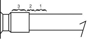
Scroll Suction Tube Brazing
- Heat Area 2 until braze temperature is attained, moving torch up and down and rotating around tube as necessary to heat tube evenly. Add braze material to the joint while moving torch around joint to flow braze material around circumference.
- After braze material flows around joint, move torch to heat Area 3. This will draw the braze material down into the joint. The time spent heating Area 3 should be minimal.
- As with any brazed joint, overheating may be detrimental to the final result.
‘Hipot’ (AC High Potential) Testing
Copeland Scroll compressors are configured with the motor down and the pumping components at the top of the shell. As a result, the motor can be immersed in refrigerant to a greater extent than hermetic reciprocating compressors when liquid refrigerant is present in the shell. In this respect, the scroll is more like semi-hermetic compressors that have horizontal motors partially submerged in oil and refrigerant.
When Copeland Scroll compressors are hipot tested with liquid refrigerant in the shell, they can show higher levels of leakage current than compressors with the motor on top. This phenomenon can occur with any compressor when the motor is immersed in refrigerant. The level of current leakage does not present any safety issue. To lower the current leakage reading, the system should be operated for a brief period of time to redistribute the refrigerant to a more normal configuration and the system hipot tested again. See AE4-1294 for megaohm testing recommendations. Under no circumstances should the hipot test be performed while the compressor is under a vacuum.
MAINTENANCE AND REPAIR
Service Procedures
Copeland Scroll Compressor Functional Check: A functional compressor test during which the suction service valve is closed to check how low the compressor will pull the suction pressure is not a good indication of how well a compressor is performing. Such a test will damage a scroll compressor in a few seconds.
The following diagnostic procedure should be used to evaluate whether a Copeland Scroll compressor is functioning properly:
- Proper voltage to the unit should be verified.
- Determine if the internal motor overload has opened or if an internal motor short or ground fault has developed. If the internal overload has opened, the compressor must be allowed to cool sufficiently to allow it to reset.
- Check that the compressor is correctly wired.
- Proper indoor and outdoor blower/fan operation should be verified.
- With service gauges connected to suction and discharge pressure fittings, turn on the compressor. If suction pressure falls below normal levels the system is either low on charge or there is a flow blockage in the system.
- Three phase compressors – If suction pressure does not drop and discharge pressure does not rise to normal levels, reverse any two of the compressor power leads and reapply power to make sure the compressor was not wired to run in reverse. If pressures still do no move to normal values, either the reversing valve (if so equipped) or the compressor is faulty. Reconnect the compressor leads as originally configured and use normal diagnostic procedures to check operation of the reversing valve.
- To test if the compressor is pumping properly, the compressor current draw must be compared to published compressor performance curves using the operating pressures and voltage of the system. If the measured average current deviates more than +/-20% from published values, a faulty compressor may be indicated. A current imbalance exceeding 20% of the average on the three phases of a three-phase compressor should be investigated further. A more comprehensive trouble-shooting sequence for compressors and systems can be found in Section H of the Emerson Climate Technologies Electrical Handbook, Form No. 6400.
- Before replacing or returning a compressor, be certain that the compressor is actually defective. As a minimum, recheck compressors returned from the field in the shop or depot by testing for a grounded, open or shorted winding and the ability to start. The orange tag in the service compressor box should be filled out and attached to the failed compressor to be returned. The information on this tag is captured in our warranty data base.
Compressor Replacement After a Motor BurnIn the case of a motor burn, the majority of contaminated oil will be removed with the compressor. The rest of the oil is cleaned with the use of suction and liquid line filter driers. A 100% activated alumina suction filter drier is recommended but must be removed after 72 hours. See AE24-1105 for clean up procedures and AE11-1297 for liquid line filter-drier recommendations. It is highly recommended that the suction accumulator be replaced if the system contains one. This is because the accumulator oil return orifice or screen may be plugged with debris or may become plugged shortly after a compressor failure. This will result in starvation of oil to the replacement compressor and a second failure. The system contractor should be inspected for pitted/burnt contacts and replaced if necessary. It is highly recommended that the run capacitor be replaced when a single phase compressor is replaced.General Guidelines and More Information
For general Copeland Scroll compressor and CO2 refrigerant please log in to Online Product Information at Emerson.com/OPI, refer to the Application Engineering bulletins listed below, or contact your Application Engineer.
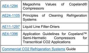
Table 1 ZO Family Models
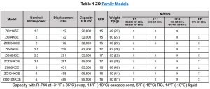
Note: Refer to form 93-11 for the latest approved refrigerants and lubricants for Copeland products.
Table 3 Crankcase Number Kits
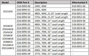
Table 4 OMC CO2 Specifications
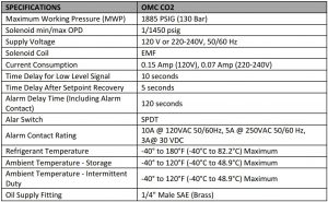

Figure 1 CO2 Low Temp. Subcritical DX System
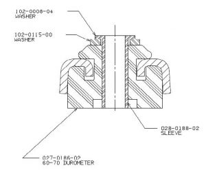
Figure 2 Specially designed rubber rommets Kit # 527-0157-00
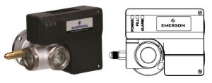
Figure 3 Oil Management Control OMC-CO2

Figure 4 Suction Side Pressure Relief Valve Requirements
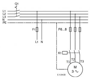
Figure 5 Three Phase Power Circuit
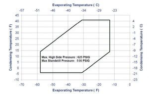
Figure 6 – ZO Compressor Operating Envelope
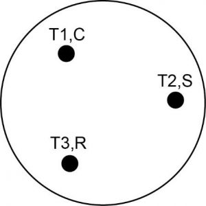
Figure 7 Compressor Electrical Connection
The contents of this publication are presented for informational purposes only and are not to be construed as warranties or guarantees, express or implied, regarding the products or services described herein or their use or applicability. Emerson Climate Technologies, Inc. and/or its affiliates (collectively “Emerson”), as applicable, reserve the right to modify the design or specifications of such products at any time without notice. Emerson does not assume responsibility for the selection, use or maintenance of any product. Responsibility for proper selection, use and maintenance of any Emerson product remains solely with the purchaser or end user.
© 2019 Emerson Climate Technologies Inc.
Copeland Scroll Compressors for CO2 Subcritical Refrigeration R-744 User Manual – Copeland Scroll Compressors for CO2 Subcritical Refrigeration R-744 User Manual –
Questions about your Manual? Post in the comments!
[xyz-ips snippet=”download-snippet”]